Application of DESA Design Method in
Object-Oriented Software Systems
Yee Soon Lim and Martin G. Helander
Abstract
—
To reduce complexity in software systems it isessential to minimize the functional dependencies in them. Functional dependency can be caused by the internal logic (model) of the system as well as the user interface. It is then vital to locate the source of the dependency, so that it can be removed. Our method “Design Equations for Systems Analysis”, or DESA, offers an opportunity to accomplish this. It allows separate examination of the model and the user interface when evaluating functional dependencies. This study investigates this potential of DESA in identifying coupled relationships. We used an object-oriented game application as a case study. DESA was found to effectively reduce the complexity of object-oriented software systems.
Index Terms—DESA, functional dependency, model and user interface subsystems, object-oriented design, software system complexity.
I. INTRODUCTION
A software system is inherently complex due to many dependencies between the various components that constitute the software. The dependencies between components impede maintenance, modification, and extension, which are constantly required in software systems. To minimize these dependencies, object-oriented design, which is a prevalent software design method, can be employed [1]. C++ and Java are programming languages that conform to this method, and have the potential to increase the modularity of software systems. Modularity is defined as a particular design structure, in which parameters and tasks are interdependent within units (modules) and independent across them [2].
However powerful in increasing software modularity, object-oriented design alone will not reduce software complexity [3], [4]. This is because in object-oriented design, software concerns are intuitively separated into distinct entities – often based on experience. However, to reduce complexity software concerns must also be explicitly separated into functions. A minimally complex software system will allow functions to be modified or added independently, without disrupting other functions. This will then ease maintenance, modification, and extension [3]. Such functional independence is not ensured in object-oriented design – for example, one class may contain two or more functions, which are highly inter-dependent, as dependencies
are not controlled within a class. Therefore, object-oriented design may still produce complex software systems. In other words, object-orientation offers the necessary but not the sufficient conditions for reducing complexity. A software design method that overcomes this shortcoming is presented in the following subsection.
A. Complementing Object-Oriented Design with Axiomatic Design
ADOSS (Axiomatic Design of Object-oriented Software Systems) is a software design method that minimizes dependencies between functions of an object-oriented software system [5]. It utilizes axiomatic design which is a method that minimizes dependencies between functions of a complex system [6]. The procedure of ADOSS is summarized in the following paragraphs.
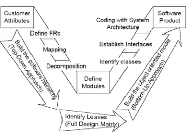
ADOSS employs a V model [7] for software design (Fig. 1). The left side of the model represents a top-down approach in building the software hierarchy, in which axiomatic design is employed; the right side represents a bottom-up approach in building the object-oriented model, in which object-oriented design is employed. The V model comprises the following detailed steps:
1. Define FRs of the software system – identify customer needs of the system, and map them into FRs (functional requirements). Each FR can represent an object.
2. Mapping between domains and the independence of software functions – map every FR into a DP (design parameter). DPs are design solutions in the form of data or input for objects.
3. Decomposition of FRs and DPs – FRs are decomposed, and the results are mapped into DPs again. This decomposition process is repeated until all DPs are explicit enough to be implemented. The resultant Manuscript received May 20, 2007.
Y. S. Lim is with the Nanyang Technological University, Singapore (phone: +65 9653 9640; e-mail: [email protected]).
[image:1.612.347.531.161.291.2]M. G. Helander is with the Nanyang Technological University, Singapore (e-mail: [email protected]).
decomposition hierarchies of FRs and DPs represent the software system architecture.
4. Definition of modules / complete design matrix – a design matrix is constructed to provide a gestalt representation of the relationship between the FRs and the DPs (Fig. 2). Each row of the matrix constitutes a module of the software system. Hence, a module explicitly represents an FR – unlike object-oriented design where a module represents a class or a real entity. As a result, high modularity implies minimal dependencies between FRs, which implies low complexity.
5. Identify objects, attributes, and operations – the FR-DP pairs in the completed design matrix are translated into object-oriented design classes which comprise data and methods.
The ADOSS software design method was employed in the development of a commercial software system called Acclaro [8]. Acclaro is an interactive and general-purpose software package for designers who practice axiomatic design.
B. Shortcoming of ADOSS (Axiomatic Design of Object-oriented Software Systems)
An object-oriented software system can be decomposed into two subsystems: model and user interface [9]. The model subsystem comprises objects that are responsible for the internal logic of the system. The user interface subsystem comprises objects that are responsible for displaying model state to the user, and for getting user input to the model.
In ADOSS, both the model subsystem and the user interface subsystem are denoted as DPs (design parameters), which are intended to fulfill various FRs (functional requirements). For example, the first 4 DPs in Fig. 2 denote the model, while DP5 denotes the user interface. Hence, when constructing the design matrix to evaluate functional dependencies, the model is examined jointly with the user interface. This particular procedure is inappropriate for three reasons.
First, an FR of a software system is often fulfilled by both the model and the user interface, in collaboration. For example, if an FR is to allow a user to configure image size, the user interface will be responsible for enabling user to input the size, and the model will be responsible for getting the user input from the user interface and know the input value. Therefore, each FR should have two semantically different DPs – one to denote the model, and the other to denote the user interface.
Second, since an FR is often fulfilled by both the model and the user interface, a dependency between two FRs can be caused by either the model or the user interface, or both. It is essential to identify the source of this dependency to effectively remove it. Therefore, the model and the user interface should be examined separately when evaluating functional dependencies. This is further justified in the case study presented in section II.
Third, the model is independent of the user interface, but the latter is dependent on the former. This unidirectional dependency is inevitable, which result in all user interface DPs being dependent on all model DPs. Therefore, if the model is examined jointly with the user interface, the design matrix will be cluttered with many inconsequential Xs, as shown in the last row of the design matrix in Fig. 2. By examining the model and the user interface separately, these inconsequential Xs will be eradicated.
C. Complementing Object-Oriented Design with DESA DESA (Design Equations for Systems Analysis) is a design method, which has been demonstrated to be effective in minimizing functional dependencies within human-machine systems, by examining both the internal structure and the user interaction of the systems [10], [11]. Since DESA builds on axiomatic design, it can complement object-oriented design in an approach similar to ADOSS (Axiomatic Design of Object-oriented Software Systems). However, there are two fundamental differences between DESA and ADOSS.
First, DESA utilizes a user-centered design model (Fig. 3), where user goals (UGs) are mapped into FRs (functional requirements), followed by DPs (design parameters), and finally into user actions (UAs). This is different from the ADOSS’ V-model (Fig. 1), where customer attributes are mapped into FRs, and finally into DPs.
Second, DESA has two DP domains: model domain and user interface domain. This allows separate examination of the model and the user interface when evaluating functional dependencies. In contrast, ADOSS has only one DP domain that contains both the model DPs and the user interface DPs. Therefore, DESA has the potential to overcome the shortcoming of ADOSS presented in the preceding subsection. This potential was further investigated via a case study, in which DESA was employed to evaluate functional dependencies within an object-oriented application termed as Nim Game.
Requirement Specification
Internal Structure
Design
User Interface
Design Functional
Requireme-nts (FRs)
Design Parameters,
Model (DPms)
Goal Domain
Requirement Domain
Model Domain
Action Domain Design
Parameters, UI (DPuis)
Interaction Design
User Interface Domain
User Actions
(UAs) User
[image:2.612.52.297.54.174.2]Goals (UGs)
Fig. 3. DESAdesignmodel
X 0 0 0 0 X X 0 0 0 X X X 0 0 0 0 X X 0 X X X X X FR1 Manage
design workflow FR2 Provide deci sion-making envm FR3 Provide efficient data I/O FR4 Provide utility function
FR5 Support ease of use
[image:2.612.313.571.607.722.2]DP1 Design roadmap DP2 Provide decision -making criterion DP3 Data manager DP4 Plug-in software DP5 Graphical user interface (GUI)
II. CASE STUDY
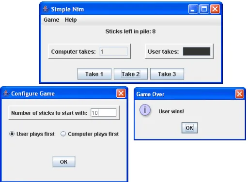
The Nim Game application was obtained from a textbook that introduces object-oriented software design in Java programming language [9]. In this application, a user player takes turn with a computer player to remove sticks from a pile of sticks, via a graphical user interface. The player who removes the last stick loses. The user is able to configure the game by specifying the number of sticks to begin with and which player plays first. The application will display the number of sticks left in the pile, display the number of sticks last taken by each player, and report the winner when the game is over.
Fig. 4 shows the screenshots of Nim Game. The “Configure Game” dialog will be displayed when user select “New Game” in the “Game” menu. The “Game Over” option pane will be displayed after the last stick is removed.
A. Nim Game Specification using DESA Design Model DESA design model, as shown in Fig. 3, was employed to aid mapping of Nim Game’s user goals to its functionality, to its model specification, to its user interface specification, and to its user actions.
The first-level UGs (user goals), in the UG decomposition hierarchy, were:
UG1 = Configure game
UG2 = Take turns with computer to remove sticks UG3 = View game state
These UGs were then mapped into FRs (functional requirements) of the application:
FR1 = Allow configuration of game FR2 = Take turns with user to remove sticks FR3 = Display game state
The difference between the UGs and the FRs is in the point of view – the UGs were explicitly specified from the point of view of user, while the FRs were explicitly specified from the point of view of the application.
The FRs were mapped into DPms (model design parameters)
of the application:
DPm1 = Game
DPm2 = Player -- Pile::remove()::sticks to take
DPm3 = Game -- Game
Each fully specified DPm contains three types of
information: the class responsible for fulfilling the functional requirement, the class method that implements the responsibility, and the data of concern. For example, in DPm2,
Pile is the class responsible for fulfilling FR2, remove is Pile’s method that removes sticks, and sticks to take is the data of concern. Besides concrete classes, the DPms may also
comprise abstract classes or interfaces.
Each DPm can have a few responsibilities, and they were
separated using the symbol “--”. For example, in DPm2, Player
is the interface responsible for determining the number of sticks to remove and then command a Pile object to remove them, while Pile is the class responsible for removing these sticks. However, Player’s method was not specified at this stage because the types of players and their strategies were yet unknown. This implies that FR2 had to be decomposed into second-level FRs. Due to similar reasons, FR1 and FR3 were also decomposed.
The responsibilities of each DPm were listed for
documentation purpose, and they were specified in <type of object>:<responsibility> format:
DPm1 = Game: get initialization data from controller
DPm2 = Interface player: determine number of sticks to take
and command pile to remove sticks Pile: remove sticks
DPm3 = Game: notify observers when game changes state
Game: know game state information
The DPms were mapped into DPuis (user interface design
parameters) of the application:
DPui1 = ConfigurationDialog::ConfigurationDialog() --
ConfigurationPanel::okPanel() --
Anonymous::actionPerformed(), NimController
DPui2 = NimInterface -- NimInterface --
NimController::sticks to take
DPui3 = NimInterface -- NimInterface -- NimInterface
The DPuis and the DPms have similar specification syntax.
However, they are different from a semantic perspective – the DPms are responsible for implementing the internal logic of
the application, while the DPuis are responsible for
implementing the user interface.
The responsibilities of each DPui were also listed for
documentation purpose:
DPui1 = View: display dialog for user to input initialization
[image:3.612.313.569.49.237.2]data
Controller: listen to "OK" button of dialog for initialization data
Controller: pass initialization data to game DPui2 = View: display components for interface player to
remove sticks
Controller: listen to components for number of sticks to remove
Controller: pass number of sticks to remove to interface player
DPui3 = View: display components for user to view game
state
View: observe game to update state changes
View: query game state and write it to components, when game changes state
The DPuis were then mapped into UAs (user actions), which
are actions that a user has to perform to achieve the UGs:
UA1 = Interact with "Configure Game" dialog that pops up after clicking on "New Game" menu item of "Game" menu. Click on "OK" button after configuration
UA2 = When text field of "Computer takes" panel is highlighted, wait for computer to remove sticks. When text field of "User takes" panel is highlighted, interact with remove stick panel
UA3 = View panels that display game state
The first-level user goals and functional requirements were decomposed, and the mapping process was repeated. The decomposition ended at second-level, because the DPms, DPuis,
and UAs had been fully and clearly specified. Table I shows the first and second-level UGs, FRs, DPms, DPuis, and UAs.
B. Dependency Analysis of Nim Game
Design matrices of Nim Game were constructed to obtain a gestalt representation of dependencies within the application. Based on DESA design model (Fig. 3), four matrices were constructed: UG-FR matrix, FR-DPm matrix, DPm-DPui matrix,
and DPui-UA matrix. The implications of these matrices are
discussed in the following paragraphs.
Fig. 5 shows the UG-FR matrix of Nim Game. ‘X’ represents has mapping, ‘0’ represents no mapping, and a blank square represents inconsequential parent-child mapping. Absence of off-diagonal ‘X’ implies that user goals were mapped to functional requirements in a one-to-one mapping; there were no one-to-many mappings or many-to-one
mappings. Therefore, the functional requirements did not cause any dependencies between the user goals, since each user goal was satisfied by an independent functional requirement. Such functional specification with a diagonal matrix is optimal, since it signifies a one-to-one relationship.
The FR-DPm matrix of Nim Game is similar to its UG-FR
matrix shown in Fig. 5, but the implications are different. In the FR-DPm matrix, an off-diagonal ‘X’ represents a
dependency between two FRs caused by their DPms. Two FRs
are concluded to be dependent when modification of one of their DPms affects the other DPm. For example, since DPm2.1
and DPm2.2 have similar methods and data of concern, which
is to determine number of sticks to take and command a Pile object to remove them, they are likely to share software code. If one class, Player, is used to contain these two similar methods, there will be no access restrictions between them, which will result in many cross-references. Modifying DPm2.1
will affect DPm2.2, and vice versa. Hence, FR2.1 and FR2.2
will be inter-dependent on each other, which are indicated by the two off-diagonal ‘X’s in Fig. 6. The model is the source of this inter-dependency, not the user interface.
Since different classes, IndependentPlayer and InteractivePlayer, were used to contain the similar methods between DPm2.1 and DPm2.2, the inter-dependency is absent
in the application (Fig. 7). In fact, none of the DPms cause
dependencies between the FRs, which result in the full FR-DPm matrix being diagonal.
The functional dependencies mentioned in the preceding paragraphs are different from client-server dependencies. A client object is dependent on a server object, because the former invokes the methods of the latter. For example, in DPm2.1, class IndependentPlayer is the client, while class Pile
is the server, because an IndependentPlayer object invokes the
[image:4.612.59.550.50.153.2]remove method of a Pile object and passes sticks to take as the
Fig. 5. UG-FR design matrix of Nim Game
FR2.1: Determine no. of sticks to remove FR2.2: Allow user to remove sticks
DPm2.1: IndependentPlayer::takeTurn() -- Pile::remove()::sticks
DPm2.2: InteractivePlayer::setNumberTo Take()-takeTurn()-- Pile::remove()::sticks
Fig. 7. Absence of off-diagonal ‘X’s imply that DPm2.1 and DPm2.2 do not cause any dependency between FR2.1 and FR2.2
FR2.1: Determine no. of sticks to remove FR2.2: Allow user to remove sticks
DPm2.1: Player::computerTakeTurn() -- Pile::remove()::sticks
DPm2.2: Player::setNumberToTake()- userTakeTurn() -- Pile::remove()::sticks
argument. Hence, IndependentPlayer is dependent on Pile – IndependentPlayer’s code that invokes remove depends on
how remove is specified in Pile. Such client-server
dependency is not denoted in the design matrices. Nevertheless, other tools, such as the dependency structure matrix [12], [13], can be employed to analyze client-server dependencies [14], [15].
The DPm-DPui matrix has an implication similar to the
FR-DPm matrix presented in the preceding paragraphs. In the
DPm-DPui matrix, an off-diagonal ‘X’ represents a dependency
between two FRs caused by their DPuis – modification of one
DPui affects the other DPui. For example, Nim Game has to
display three types of game state information: sticks left in pile, sticks last taken by computer, and sticks last taken by user (Fig. 4). Hence, the user interface subsystem has to display three almost identical panels on the graphical user interface, which contain the game state information. To avoid duplicate code when programming these panels, we can program one class Panel, and then create three instances of Panel during run-time. However, having to modify “sticks left in pile” panel implies that the other two panels will experience identical modification, and vice versa. This is undesirable because “display sticks last taken” and “display sticks left in pile” are different functions, FR3.1 and FR3.2 respectively (Table I) – it is likely to have to modify one without changing the other. As a result, FR3.1 and FR3.2 are inter-dependent, which is represented by the two off-diagonal ‘X’s in Fig. 8. The user interface is the source of this inter-dependency, not the model.
This inter-dependency can be avoided by using a class ReportPanel to model the “sticks left in pile” panel, and a separate class PlayerPanel to model the other two panels (Fig. 9). This is actually the design employed in the application. In reality, none of the DPuis cause dependencies between the FRs,
which result in the full DPm-DPui matrix being diagonal.
The DPui-UA matrix has an implication different from the
two preceding matrices, FR-DPm matrix and DPm-DPui matrix.
An off-diagonal ‘X’ in the matrix represents a dependency between two UGs (user goals) caused by their UAs (user actions) – when users execute one of the UA, the other UA will be affected. This affects the users of the application,
instead of the designers. Such source of dependency is more common among process control applications, where user interactions may be coupled [11], [16]. The DPui-UA matrix of
Nim Game is diagonal.
III.CONCLUSION
DESA is effective in reducing the complexity of object-oriented software systems, as it minimizes the functional dependencies. Functional dependency can be caused by either the model subsystem or the user interface subsystem, or both, and DESA can locate the cause. Furthermore, DESA can aid object-oriented software designers to identify a suitable collection of classes for various software systems, and to allocate appropriate responsibilities to the classes by using functional independence as the criterion.
REFERENCES
[1] R. Wirfs-Brock, B. Wilkerson, and L. Wiener, Designing Object-Oriented Software (Book style). Englewood Cliffs, NJ: Prentice-Hall, 1990.
[2] C. Y. Baldwin and K. B. Clark, Design Rules, Vol. 1: The Power of Modularity (Book style). Cambridge, MA: The MIT Press, 2000. [3] N. P. Suh, Axiomatic Design: Advances and Applications (Book style).
New York, NY: Oxford University Press, 2001, ch. 5, pp. 239–298. [4] T. Oktay, “Axiomatic design of shop floor programming software,” in
Proceedings of the 4th International Conferenceon Axiomatic Design,
ICAD2006, Florence, Italy.
[5] S. H. Do and N. P. Suh, “Object-oriented software design with axiomatic design,” in Proceedings of the 1st International Conference on Axiomatic
Design, ICAD2000, Cambridge, MA.
[6] N. P. Suh, The Principles of Design (Book style). New York, NY: Oxford University Press, 1990.
[7] B. El-Haik, “The integration of axiomatic design in the engineering design process,” 11th Annual RMSL Workshop, May 12 1999, Detroit,
MI.
[8] S. H. Do and N. P. Suh, “Axiomatic design of software systems,” CIRP Annals,vol. 49, no. 1, pp. 95–100, 2000.
[9] J. Nino and F. Hosch, An Introduction to Programming and Object Oriented Design using Java (Book style).New Jersey, NJ: John Wiley & Sons, 2005.
[10] M. G. Helander, “Using design equations to identify sources of complexity in human-machine interaction,” Theoretical Issues in Ergonomics Science,vol. 8, no. 2, pp. 123–146, 2007.
[11] S. Lo and M. G. Helander, “Use of axiomatic design principles for analysing complexity of human-machine systems,” Theoretical Issues in Ergonomics Science, vol. 8, no. 2, pp. 147–169, 2007.
[12] D. V. Steward, “The design structure system: a method for managing the design of complex systems,” IEEE Transactions in Engineering Management, vol. 28, no. 3, pp. 71–84, 1981.
[13] S. D. Eppinger, “A planning method for integration of large-scale engineering systems,” in Proceedings of the 11th International
Conference on Engineering Design, ICED97, Tampere, Finland. [14] K. Sullivan, Y. Cai, B. Hallen, and W. Griswold, “The structure and
value of modularity in software design,” in Proceedings of the 8th European Software Engineering Conference held jointly with 9th ACM SIGSOFT International Symposium on Foundations of Software Engineering, ESEC/FSE’01, Vienna, Austria.
[15] N. Sangal, E. Jordan, V. Sinha, and D. Jackson, “Using dependency models to manage complex software architecture,” in Proceedings of the 20th ACM Conference on Object-Oriented Programming, Systems, Languages, and Applications, OOPSLA’05, Broadway, NY.
[16] K. J. Vicente, Cognitive Work Analysis: toward Safe, Productive, and Healthy Computer-Based Work (Book style). Mahwah, NJ: Lawrence Erlbaum Associates, 1999.
[17] S. Lo and M. G. Helander, “Method for analyzing the usability of consumer products,” in Proceedings of the 3rd International Conference
on Axiomatic Design, ICAD2004, Seoul, Korea. DPm3.1: Player::takeTurn()
-- AbstractPlayer::setSticksT aken()-sticksTaken()::sticks
DPm3.2: Game::play() -- Game::sticksLeft(), Pile::sticks()::sticks
DPui3.1: Panel::Panel() -- PlayerView::PlayerView() -- PlayerView::update()::sticks
DPui3.2: Panel::Panel() -- NimController::initializeGame() -- NimInterface::update()::sticks
Fig. 9. The two off-diagonal ‘X’s imply that DPui3.1 and DPui3.2 cause an inter-dependency between FR3.1 and FR3.2
DPm3.1: Player::takeTurn() -- AbstractPlayer::setSticksT aken()-sticksTaken()::sticks
DPm3.2: Game::play() -- Game::sticksLeft(), Pile::sticks()::sticks
DPui3.1: PlayerPanel::PlayerPan el() -- PlayerView::PlayerView() -- PlayerView::update()::sticks
DPui3.2: ReportPanel::ReportPanel ()-- NimController::initializeGame ()--NimInterface::update()::sticks
T ABLE I D ECOM POSED UG S , FR S , D Pm S , D Pui S , AND UA S UGs ( U se r Goals ) FRs ( F un ctional R equi rem ent s) DP m s (Desig n Param eters, M odel ) DP ui s (Desi g n Param eters, UI ) UAs ( U se r Actions ) 1 Co nfigu re gam e Allo w co nf igu ration of gam e Game ConfigurationD ialog ::C onfigu ra tionDialog() -- ConfigurationP an el::okP anel() -- Anonymous::ac tionP erfo rmed(), NimControll er Interact with "Con fig u re Ga m e" dialog th at po ps u p after click ing o n "New Gam e" m enu i te m of " G am e" m enu. Click on "OK" bu tto
n after con
fi g uratio n 1. 1
Specify num
ber of stick s to start Allo w
specification of num
ber of stick s to start Game::Game() -- Pi le::P ile()::starting sticks ConfigurationP anel::sticksP an el() -- ConfigurationP anel::startingS ticks() -- Anonymous::ac tionP erformed(), NimController: :setStartingS ti cks()- initializeGame()::starting stic ks En ter nu m b er o f stick s t o start in tex t fi el d of " N um ber of st ic ks t o s tart wi th " panel 1. 2
Select user play
s fi rs t or not Allo w selection of use r pl ay s
first or n
o t Game::Game() ::first play er ConfigurationP anel ::firstPlayerP anel() -- ConfigurationP anel::f irstPlayerP anel() -- Anonymous::ac tionP erformed(), NimController: :setUserPlaysFirst()- initializeGame()::first player C li ck o n " U ser pl ay s fi rst " ra di o b u tt o n or "C om put er pl ay s fi rst " ra d io b u tt o n 2 T ak e turn s with com puter to rem ove st ic ks T ak e turns with user t o rem ove stick s
Player -- Pile::remove()::sticks to take NimInterface -- NimInterface -- Nim
C
ontroller:
:s
tick
s to tak
e Whe n t ext fi el d of "C om put er t akes" panel i s hi ghl ight ed , wai t f o r com put er to rem ove st ic ks. Wh en t ext f iel d o f "User tak es" pan el is h igh ligh ted , in
teract with rem
o v e stick p anel 2. 1 Allo w com puter to rem ove st ic ks Determ in e num ber of stick s to rem o ve IndependentPl ayer::takeT urn() -- Pi
le::remove()::sticks to take
Autom ated Aut o m ated 2. 2 R em ove stick s Allo w u ser t o rem ove st ic ks InteractivePlay er::setNumber To Ta ke()-takeT urn() -- Pi
le::remove()::sticks to take
NimInterface::buttonP anel() -- NimInterface::buttonP anel() -- NimController: :actionP er formed()::sticks to take Click on "T ak e 1 " bu tto n, "T ak e 2 " but to n, o r "T ak e 3" b u tt on 3 Vi ew g am e state Display gam e state G
ame -- G
ame
NimInt
er
fac
e -- NimInt
er
fac
e -- NimInt
er fac e V iew pa nel s t h at di spl ay gam e st at e 3. 1 V iew num ber o
f sticks last
ta ken Di spl ay num ber o f stick s last ta ken Player::takeT ur n() -- AbstractPlayer ::setSticksT aken()- sticksT
aken()::sticks last taken
PlayerP anel::Pl ayerP anel() -- PlayerV iew::Pl ayerV iew() -- PlayerV
iew::update()::sticks last taken
V iew t ext fi el d o f "C om put er t akes" panel a n d t ext fi el d of " U se r t akes" panel 3. 2 V iew num ber o f stick s left in p ile Di spl ay num ber o f stick
s left i
n
p
ile
Game::play() -- Game::sticksL
eft(),
Pi
le::sticks()::sticks left in pil
e Re portP anel::R eportP anel() --NimController: :initializeGame() --
NimInterface::update()::sticks left in pile
V iew "S tick s l eft in p ile" p anel 3. 3 K now w inn er of gam e R epo rt wi nne r of gam e
Game::play() -- Game::gameO
ver() --
Game::winner(
)::player who won
NimController:
:initializeGame() --
NimInterface::update() -- NimInterface::reportW
inner()
::player who won
![Fig. 2. Design matrix of the Acclaro software at first-level decomposition [8]](https://thumb-us.123doks.com/thumbv2/123dok_us/1332475.664334/2.612.313.571.607.722/fig-design-matrix-acclaro-software-level-decomposition.webp)