Abstract— This paper will discuss the use of a new scheme to conduct conformance testing of the Controller Area Network (CAN) protocol implemented in a soft core, using Virtual I/O and integrated logic analyzers. Virtual I/O is particularly helpful in generating bit pattern’s on a CAN bus which are accurate to a single CAN bit time, as these patterns are generated using the same system clock rather than an external clock as is the case of a bench pattern generator. Based around simple off-the-shelf development boards, general purpose software code and the simple analysis tool Chipscope, the proposed method allows developers to verify the bit timing properties of a CAN soft core against the relevant ISO standards. Finally, we describe the use of a test bed in the verification of an open-source CAN soft core implementation.
Index Terms—CAN, Conformance Testing, Chipscope VIO, Bit time, Soft Core
I. INTRODUCTION
Conformance testing is an integral part of any protocol development, as it tests the behavior and capabilities of an implementation against the requirements set by a standard [1]. Controller Area Network (CAN) is a widely used protocol for distributed systems [2]. Many different CAN controllers (e.g. [3], [4]) are widely available in integrated circuit form; as such they cannot be modified, although in many cases a flexible implementation will be required for a given system implementation. In the context of the current paper, a CAN implementation was required for an ongoing project [5] which could be modified to add new features based, primarily on hardware implementation of CAN-based shared clock scheduler [6]. Hence, to make the desired changes a soft core solution was required and implemented on an FPGA and programmed in Verilog HDL [7].
FPGA’s provides full internal visibility using integrated logic analyzers ILA like Signal Tap [8] and Chipscope pro [9]. These tools provide small and efficient cores to debug not only I/O but also internal signals, and provide real time
1Manuscript received March 23, 2009. This work is part of the PhD studies
of Mr. Imran Sheikh and is supported by NWFP University of Engineering & Technology, Peshawar, Pakistan.
I. Sheikh is with ESL, Engineering Department, University of Leicester, UK, LE1 7RH. (tel: +44-116-2522578; e-mail: [email protected]).
M. Short is a lecturer in Embedded Systems at the University of Leicester, UK. (tel: +44-116-2525052; e-mail: [email protected]).
K.F. Athaide is a PhD student at ESL. (e-mail: [email protected]).
in-system debugging features via JTAG. One other major feature which is provided by Chipscope is the capability for Virtual Input Output (VIO), which is implemented as a customizable core and can stimulate a design using pulse trains which can be either synchronous or asynchronous to the system clock.
ISO has developed a standard CAN Conformance testing Document [10] and for any device to be declared CAN conformant, evidence is required that shows the testing procedures outlined in the standard have been performed and passed without problem. The ISO document not only specifies different types of tests that must be performed for conformance testing, but also specifies a required Test Plan (TP) architecture [1]. The TP architecture indicates that the tester should be divided into two parts. The first component is the Lower Tester (LT) which provides the test pattern generation and analysis. The second is termed the Upper Tester (UT), which is required to contain the software to control the CAN Implementation under Test (IUT). The UT is normally a host processor or programmable device of some kind, and also provides coordination to conduct the tests between the LT and the IUT [11]. The UT receives stimulus (with details of the test being performed) from the LT, and generates messages passed on to the IUT. The IUT then processes these messages, and both the UT and LT components monitor its behavior for consistency with the CAN protocol. If the result is satisfactory, the test is considered passed and testing proceeds to the next conformance test. It should be noted that the testing procedures that are required to be implemented include coverage of common error conditions, randomized tests and also bit timing tests. Most tests are critical, and the latter category – bit timing – contains a number of tests that can be difficult to localize, and a suitable means is required to capture and display multiple logic signals over an appropriate timescale. This typically requires the use of dedicated hardware and Logic Analyzers [12].
Traditionally, CAN controllers and transceivers have been implemented at the silicon level, either by dedicated IC’s or as on-chip peripherals of embedded devices. Also, the implementation of CAN conformance testers has traditionally been done using dedicated hardware coupled with specially written analysis software; this is a practical approach to such testing prior to high-volume IC manufacture. However, recent years have seen an increased interest in the employment of CAN-enabled devices implemented by programmable hardware devices such as FPGA’s. As is the case with the project outlines in [5], such soft core implementations are often needed in small-volume
Using Virtual I/O for CAN Bit Timing
Conformance Tests
1
(or even one-off) batches. In these circumstances, cost and availability reasons often dictate that it is not practical for developers to use traditional CAN-conformance testing equipment.
To help alleviate this problem, a previous paper proposed a low-cost and easily implemented method [33]. The current paper will extend this previous approach by proposing a VIO-based scheme to include test cases related to CAN bit-timing, arguably the most difficult area of CAN-conformance testing to perform. This technique allows a CAN soft core implementation to be fully tested for conformance to the relevant standard without the need for expensive or proprietary hardware interfaces and logic analyzers.
The remainder of the paper is organized as follows: In the next Section, different implementations of the CAN conformance testing before and after the ISO testing standard evolved will be described. Section 3 describes the formation of the current test bed for CAN conformance testing. Section 4 presents the case studies involving two of the tests being carried out by the proposed approach to CAN conformance. Section 5 will present the analytical comparison of the proposed approach to other techniques used for conformance testing. Section 6 presents initial conclusions.
II. PREVIOUS WORK IN THIS AREA
One of the earliest CAN prototype controllers was named DBCAN [14]. This implementation was tested using a logic analyzer and a pattern generator circuit. As there was no standard for conformance testing at the time the prototype was developed, a commercial basic (as opposed to full) CAN controller was used as benchmark for verification. A major disadvantage of this scheme was the use of external interface modules to visualize the state of different DBCAN registers, and the testing procedure was somewhat limited in the number of signal channels that could be simultaneously analyzed. Since this is a needed requirement in the case of ISO standard conformance testing – the ability to visualize the state of large numbers of CAN registers simultaneously is a prerequisite – such a setup is limited in this respect.
A slightly different verification technique was reported by [15]. Their technique employed custom design boards with 8051 microcontrollers and SJA1000 CAN controllers, but this method involved the design of specialized interface hardware and boards to assist with the testing plan. Specialized verification architecture for testing automotive protocols (including CAN) at both the module and chip level was proposed by [16]. Again, this work requires a specially designed CAN verification component as part of the silicon, while the selection and implementation of actual test sequences, along with the selection of a suitable means to monitoring bus signals, is left open for the tester.
With respect to soft core CAN implementations, the CAN e-Verification (CANeVC) test bench has previously been described [17]. This commercial test facility requires a CAN specification core to be embedded in the netlist; this core then runs specific tests to verify the behavior of the CAN soft core. Again, this technique involves a time consuming development of a test bench using an expensive commercially available verification IP ; additionally, compatibility issues often arise when using CAN implementations other than the proprietary implementation
[18], and only a limited number of programmable logic devices are supported. Finally, several experimental implementations (such as that reported by [19]) to measure single parameters - such as CAN bit errors - rather than perform complete conformance testing have been described in the literature. Such implementations have typically used complex and non-trivial means, requiring customized hardware and software. In summary then, it can be observed that - to date – specialized hardware and / or software has been required to assist with CAN testing plans. In the following Section, a novel testing approach that relies only upon the use of low-cost, standard off-the-shelf hardware and software is described.
III. TEST BED A. Architecture
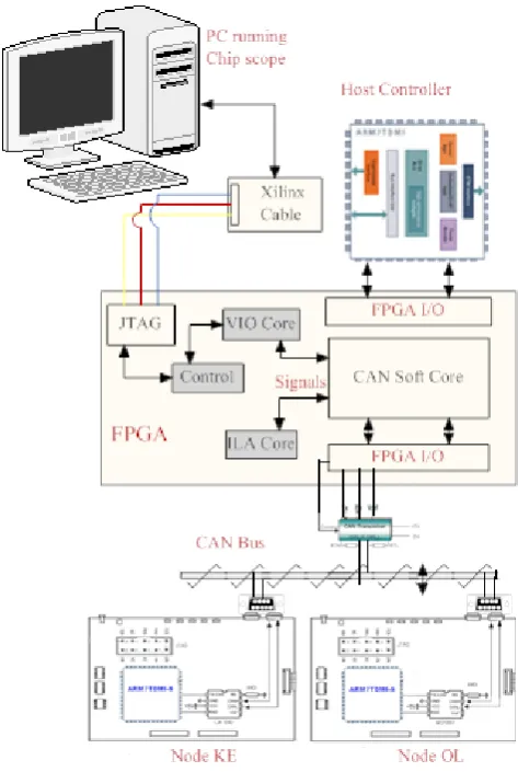
[image:2.595.307.544.335.688.2]Real-time testing of a soft core CAN implementation is an extremely complicated procedure; the hardware that was employed for this purpose (as described in [5][33][20]) is shown in Fig 1. The hardware and software components are briefly described below, along with the use of VIO to generate the required test patterns.
Fig 1: Test Bench
1) Hardware
cores is to simultaneous verify their behavior as both CAN Transmitters/Receivers, additionally to generate special patterns on the CAN bus using VIO plus additional modules embedded within the soft core.
• Two ARM7 microcontroller boards with integrated CAN controller and transceivers. These boards are used as receivers of CAN messages, for further verification of the messages sent by the CAN soft cores. These boards are also used to induce error’s on the CAN bus [13].
2) Software
• Xilinx ISE [21] for soft core programming, synthesis and routing / programming the FPGA.
• Chipscope Pro is used as the primary analysis tool. The VIO core is used to generate and control different bit patterns.
• The Keil uVision 3 IDE [22] with GNUARM tools. This free C compiler and toolchain was chosen for programming and debugging the Microcontroller boards.
B. Use of Virtual I/O for Test pattern generation
The Virtual Input/output (VIO) core can be used to analyze and drive internal FPGA signals in real-time [9]. The VIO cores can generate both asynchronous and synchronous signals, to be used as both input and output to / from the system. In the testing method proposed in this paper, synchronous outputs have been used as either a sole source of test pattern generator, or used in conjunction with soft modules added with the CAN functionality in the soft core, as described in [13]. VIO synchronous output has the ability to output a static 1, a static 0, or a pulse train of successive
values [13]. A pulse train is a 16-clock cycle sequence of 1's and 0's that is driven out of the core on successive clock cycles. The outputs can either be seen directly as the synchronous inputs, or a more comprehensive method is to use Chipscope ILA. Chipscope can analyze up to 16 internal signal ports in a single core, with each port having up to 256 signals with a capture depth of 16K samples. Different logical trigger conditions may also be setup to analyze signals for a certain value - as for example setting up a trigger to analyze when a CAN error frame is generated, or using ILA to capture multiple instances of stuff bits inside a capture window [9].
When using pattern generators, test vectors are first stored and are subsequently sent on the CAN bus when required; thus, the IUT can be put in different states as and when required, allowing its behavior and responses to be analyzed. In the proposed test bed, FPGA-based pattern generation has been employed, which is economical (as no extra costs are added to the test setup) but it is also flexible (it is added as a Verilog module to the main CAN core along with a VIO Core). This setup allows accurate production of the special conditions required to test conformance of CAN bit-timing; for example in test case 1 (to be reported in the next Section), it is required to delay a sample point by only two time quanta (on a recessive to dominant edge) on an IUT working as a transmitter [1]. Such precise control of test patterns could not be achieved with the previous setup.
This test pattern was easily achieved by modifying the VIO Verilog module, without the need to modify the actual functionality of the CAN soft core (non-invasive testing). The Chipscope VIO was used as an (external synchronous) 5 bit pulse input “delay_add”, to generate an ‘n’ time quanta delay to the sample point. An example Verilog code is given below to help illustrate this:
always @ (posedge Clock or posedge Reset) begin
if (Reset) Delay <= 4'h0;
else if (Resynchronization & Phase_Segment1 & (~Transmitting | Transmitting & (Next_Bit_to_Tx | (CAN_Tx & (~CAN_Rx)))))
Delay <=#Tp (Time_Quanta_Count > {3'h0, SJW})? ({2'h0, SJW} + 1'b1) : (Time_Quant_Count + 1'b1); /* Extra Code Added to set a delay using VIO*/
else if (delay_add[0] & Transmitting & Next_Bit_to_Tx & (~CAN_Tx)) Delay <= delay_add;
else if (go_sync | go_seg1) delay <=#Tp 4'h0; end
IV. TEST CASES
The proposed test facility was employed to test the CAN conformance of a custom created CAN soft core. As the number of total number of test cases to consider in any single CAN conformance test plan is numerous, it is beyond the scope of the current paper to present comprehensive test results; comprehensive test results are available in the form of technical report [20]. However, in this Section we will present two test cases that help highlight the main features of the proposed facility, specifically with respect to the bit
timing and error management classes of tests [1]. Both tests were carried out successfully, and are described in the following two Sections.
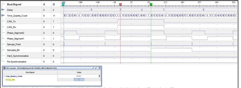
A. Non synchronization on Dominant bit transmission
Fig 2: Chipscope Snapshot for Test Case A. This test requires two instances of the CAN Soft Core,
each behaving as a transmitter and receiver. Also the ARM7 node (OL in Fig 1) is employed to verify the correctness of the transmission. The VIO core was setup so that when the appropriate user stimulus is provided, a 2 time quanta extension is added to the phase segment 1, effectively delaying the sample point. In normal circumstances the VIO core is sourced using the system clock (which in this case is 48 MHz). Therefore the DCM module [23] plus an additional gated clock was employed to generate a clock signal equal to the amount of a single CAN bit time (250 Kbps in this case), so any synchronous signal generated by VIO will last for a full single CAN bit time.
This test was executed successfully with the desired result; the observation on the transmitter node from the Chipscope - shown in Fig 2 – is as follows:
1) The default values of Phase Segment1 are 10 time quanta and Phase Segment2 is 5 time quanta, when the ‘Delay’ Bus value is Zero.
2) The ‘delay_add’ signal on the VIO console is the synchronous input and when a user applies the input pulse it generates a delay as shown by the value of ‘Delay’ bus value at Marker ‘T’ (As Delay=2 was set as a Trigger condition).
3) The value of marker ‘O’ (for Time_Quanta_Count) can be observed to be 11 (Count starts from 0), which is 2 more than the normal phase segment1 value.
4) Adding this 2 time quanta delay before the dominant to recessive edge results in the edge having a positive phase error of 2 time quanta.
5) The Sampled_bit signal represents the CAN_Rx signal at the sample point. As can be seen, the Sampled_Bit value for recessive to dominant edge happened on the ‘Sample point’ after Marker ‘O’.
6) The ‘Resynchronization’ signal represents any resynchronization events occurring in case of a positive (or negative) phase error on an edge. As can be seen, this signal remains low thus demonstrating that no resynchronization happened (the desired result).
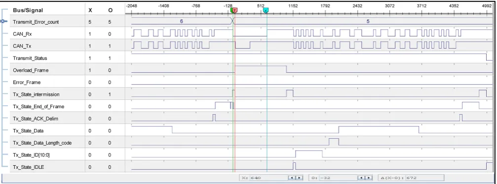
B. TEC non-increment on 13 bit long Overload Flag
The purpose of this test is to verify that an IUT acting as a transmitter doesn’t change the value of it’s transmit error counter (TEC) when receiving a 13 bit long overload flag. The test is setup using two instances of CAN soft core, one acting as the IUT while the other acts as the LT. The LT requests an overload frame, and generates 13 dominant bits of overload flag. The overload request is generated using a VIO synchronous input and then a 13 bit dominant value on the CAN_Tx signal. Snapshots for this test case are given at both LT (Fig 3) and the IUT node (Fig 4). The system clock for this test case is 12 MHz. A VIO console is shown in Fig 3, with a synchronous input overload_request; this signal requests the overload frame (which can only be requested by the receiver) between two data frames sent by a transmitter. 1) The signal ‘Overload_Request’ is also shown on the ILA
screenshot, after which an overload frame is sent after the data frame is successfully received (as can be seen as the Overload_Frame signal is set high at this point). 2) The Overload Frame lasts for 13 bit times, as can be seen
by the number of Sample_points between marker ‘X’ (start of overload flag) and marker ‘O’ (end of overload frame).
Considering now the IUT snapshot:
Fig 3: Chipscope Snapshot for LT of Test Case B.
Fig 2: Chipscope Snapshot for IUT of Test Case B.
2) At marker ‘O’ (end of ‘Transmit_State_End_of_Frame’) an ‘Overload_Frame’ signal can be observed; the CAN_Rx therefore remains low between marker ’T’ (start of Overload_Frame) to marker ‘O’ (end of dominant overload flag).
3) The time difference between markers ‘O’ and ‘X’ is ‘672’; since each CAN bit time is given as 12Mhz/250Kbps= 48 clock cycles, this gives a corresponding time of 14 CAN bit times.
4) The value of the Transmit Error Counter was ‘6’ before the completion of Data frame and subsequently changes to ‘5’ after a successful completion of a data frame, as illustrated by the Transmit_State_End_Of_Frame signal.
5) After receiving 13 dominant bits of overload frame, the Error_Frame signal remains low and the Transmit Error Counter doesn’t change; this is the desired result as the IUT has not considered a 13 bit dominant overload flag as an error.
V. COMPARATIVE STUDY
This Section presents a cost and flexibility comparison between conventional CAN conformance testing hardware and software with the approached that has been discussed in this paper. The first observation is that the current facility does not require expensive CAN PC interface cards (e.g. [24], [25]) which are normally required for CAN conformance testing [26]. These cards are used to capture CAN bus data to analyze the internal status of different registers and to log the events; these cards not only required the hardware but also specialized software [27] along with interface cables which can also add to the cost and complexity of the setup. The proposed implementation allows the internal state of the CAN IUT to be directly analyzed using Chipscope, and also by using the Keil uVision 3 IDE. In addition, there are several key advantages of the proposed test bed using Chipscope over hardware logic analyzer systems and pattern generators:
[image:5.595.47.551.259.446.2]Integrated Logic analyzer. Although standard bench analyzers can typically show Mega samples, Chipscope is limited to a Sample width of 16K; however as mentioned this problem can be overcome by using a digital clock manager [23] and can hence capture enough samples to encompass 3 to 4 complete CAN messages in a single trigger.
2) Additional probes with wide numbers of I/O pins are required to interface with the logic analyzers; Chipscope can carry a large number of these signals using a single JTAG cable.
3) In addition to accessing all I/O signals, Chipscope also allows internal wires and signals to be traced [31]. This is particularly useful for CAN conformance testing, as specific triggering conditions for precise bit timing conditions can be set up, as we have demonstrated with the test cases in this paper.
4) Virtual I/O is a real time tool especially suited to pattern generation, and doesn’t require any physical interfaces or ports. Hence, it not only saves resources but doesn’t have the physical impairments of an external signal. The ability to insert VIO cores into a design allows users to interactively verify the design quickly and effectively, greatly reducing the time spent in verification.
VI. CONCLUSION
This paper has presented an approach to utilize virtual I/O’s and Integrated Logic Analyzers to perform CAN conformance testing of soft cores, in accordance with ISO standards. It has been shown that the facility is capable of performing the full range of testing required, with VIO being especially suited to the complicated tests required for CAN bit timing conformance. In conclusion, a facility such as this may be assembled and used for a fraction of the cost of a ‘regular’ test facility for CAN conformance. Further details of how each individual test may be implemented when using such a facility such as this has been described in [20].
As a final note, the authors observe that a facility such as that described in this paper is not restricted to the CAN protocol, and – with suitable modifications – can be used to test conformance of many alternate network protocols, for example TTCAN [32].
REFERENCES
[1] ISO/IEC. “Information Technology- OSI - Conformance testing Methodology and frame work- Part 1: General concepts,”ISO/IEC IS 9646-1, 1994.
[2] ISO. International Standard 11898 – Road vehicles - Interchange of digital information - Controller Area Network (CAN) for high-speed Communication, November 1993.
[3] Philips Semiconductor, SJA1000 Stand-alone CAN controller, Data Sheet, January 2000.
[4] Microchip's MCP2515 stand-alone CAN Controller with SPI Interface [5] I. Sheikh, M. Short, and M. Pont, 2008. “Hardware Implementation of a Shared Clock Protocol for CAN: A Pilot Study, “In proceedings of
4th UK EmbeddedForum, Southampton, September, 2008.
[6] D. Ayavoo, M. J. Pont, M. Short, and S. Parker, “Two novel shared-clock scheduling algorithms for use with CAN-based distributed systems", Microprocessors and Microsystems, 31(5):
326-334, 2007.
[7] IEEE standard 1364, “Standard for Verilog Hardware Description Language,” 2001
[8] Altera Inc., “Design Debugging Using the Signal Tap II Embedded Logic Analyzer,” December, 2004.
[9] Xilinx Inc: 2005, Chipscope Pro – Software and Cores User guide. 1. [10] Road Vehicles- Controller Area Network (CAN)- Conformance Test
Plan, ISO 16845:2000.
[11] E. Carmes, C. Junier,and F.Aussedat, “CAN Conformance: Methodology and Tools,” Keynote speech, CAN in Automation Proceedings of 3rd iCC 1996, Paris, October 1996
[12] W. Lawrenz, P. Kinowski, and G. Kircher, “CAN Conformance Testing-The Developing ISO Standard and Necessary Extensions,” In Proceedings of International Truck and Bus Meeting and Exposition Indianapolis, Indiana, November 16-18, 1998.
[13] H. Tan, R. F. DeMara, A. J. Thakkar, A. Ejnioui, and J. D. Sattler. “Complexity and Performance Evaluation of Two Partial
Reconfiguration Interfaces on FPGAs: a Case Study,” In Proceedings of the ERSA, 2006.
[14] A. Kirschbaum, F.M. Renner, A. Wilmes, M. Glesner, “Rapid-prototyping of a CAN-Bus controller: a case study,” In proceedings of Rapid System Prototyping, Seventh IEEE International Workshop on , vol., no., pp.146-151, 19-21 Jun 1996.
[15] K. Nimsub, K. Dawi, C. Kyuhyung, K. Jinsang, and C. Wonkyung, “Design and Verification of a CAN Controller for Custom ASIC,” CAN in Automation Proceedings of 10th iCC 2005.
[16] G. Zarri, F. Colucci, F. Dupuis, R. Mariani, M. Pasquariello, G. Risaliti, and C. Tibaldi, “On the verification of automotive protocols,” In Proceedings of Design, Automation and Test in Europe, 2006. vol.2, no., March 2006, pp.6-10.
[17] CAN 2.0 eVC, 2005. Yogitech SPA
[18] A. Di Blasi, F.Colucci, and R. Mariani,”Y-CAN Platform: A Re-usable Platform for Design, Verification and Validation of CAN-Based Systems On a Chip,” ETS- 2003 Symposium, May2003
[19] J. Ferreira, A. Oliveira, and J. Fonesca, “An Experiment to Assess Bit Error Rate in CAN,” In Proceedings of 3rd International Workshop of Real-time Networks (RTN 2004), Catania, Italy.
[20] I. Sheikh, and M. Short, “CAN Conformance Testing-A New approach,” tech-report ESL-09-01, ESL, Engineering Department, University of Leicester, February, 2009.
[21] ISE Foundation, Xilinx, Inc, 2008. http://www.xilinx.com/ise [22] uVision IDE Tool, Keil, 2008. http://www.keil.com/uvision. [23] XAPP462, Application Note, “Using Digital Clock Managers (DCMs)
in Spartan-3 FPGAs, “Xilinx Inc, 2003.
[24] . NI USB-8473, “1 Port, High Speed CAN, USB Interface,” National Instruments, 2008.
[25] CAN/CANopen/DeviceNet Interface boards. Softing AG, 2007. http://www.softing.com/home/en/pdf/ia/product-info/can-bus/D_IA_4 1E_0711_CAN_Interface_Z.pdf.
[26] W. Lawrenz, P. Kinowski, and G. Kircher, ”CAN Conformance Testing - State of the Art and Test Experience,” In Proceedings of 5th International CAN Conference iCC’98, San Jose, California, November 1998.
[27] Lab VIEW, National Instruments, 2009. http://www.ni.com/labview86/.
[28] TLA 5000B Logic Analyzers, Tektronics, Inc, 2009. http://www.tek.com/products/logic_analyzers/tla5000/
[29] 16900 Series Logic Analysis System Mainframes. Agilent Technologies,2008.
http://cp.literature.agilent.com/litweb/pdf/59890421EN.pdf.
[30] Deep Storage with Xilinx Chipscope Pro and Agilent Technologies FPGA Trace Port Analyzer., Agilent Technologies, 2003. http://cp.literature.agilent.com/litweb/pdf/5988-7352EN.pdf.
[31] T. Lee, Y. Fan, S. Yen, C. Tsai, and R. Hsiao, “An Integrated Functional Verification Tool for FPGA Systems,” Second International Conference on Innovative Computing, Information and Control, ICICIC '07, pp.203-203 5-7 Sept. 2007.
[32] T. F.hrer, B Müller, W Dieterle, F Hartwich,”Time-triggered Communication on CAN (Time-triggered CAN TTCAN)” Proceedings of iCC 2000, Amsterdam, The Netherlands, 2000.
[33] I. Sheikh, M. Short, “A Low Cost and Flexible Approach to CAN Conformance Testing,” Accepted for ICINCO 2009, 6th International
Conference on Informatics in Control, Automation and Robotics,