Abstract— This paper presents an analytical model for
calculating the deformation behavior of an elastic, composite strut comprising any number of materials, which are represented by an assembly of concentric hollow cylinder. The model is applicable for pure axial compression for short struts provided elastic instability, if any, is assessed to be of negligible effect. For a typical constituent cylinder, relationships are derived to describe the deformations along three cylindrical co-ordinate axes. Lateral interaction between adjacent cylinders is modeled based on the elastic theory, taking into account the equilibrium of individual cylinders and the elastic parameters: stress-strain modulus and Poisson’s ratio. The relationships are expressed in matrix notation and a computer program is developed to enhance rapidity of analysis. To assess the validity of the model, the program is used to analyze test data from an instrumented, steel-encased reinforced concrete column which had previously been loaded under controlled conditions in a laboratory. It is shown that the calculated and measured deformations of the column, at specified co-ordinates and along three cylindrical directions, agree to within 5%. Therefore the validity of the model is demonstrated.
Index Terms—Elastic parameters, Stresses in cylindrical
co-ordinate systems.
I. INTRODUCTION
According to published [1],[2] experimental evidence, both
the Young’s modulus and the Poisson’s ratio of concrete vary with radius on a cross-section of a cylindrical specimen. Both of these quantities could be 1.5 times greater at the centre than at the periphery of a concrete column. In the case of the composite strut analyzed here, the problem is further complicated by the presence of an external steel casing.
In the present study, a mathematical model is developed to simulate the elastic behavior of a short composite strut, comprising steel, reinforced concrete and plain concrete. The strut was instrumented and subjected to compression testing in the laboratory. Displacements in the constituent materials were measured at selected radial distances from the centre of the short column, so that the variations in the values of elastic constants with position of measurement are taken into consideration. This provides an analytical capability that represents the composite nature of the column cross-section
Dr J. R. Omer is a Research Scientist at the University of Glamorgan, Pontypridd, South Wales, CF37 1DL, United Kingdom. Telephone: +44 (0) 1443 482162; Fax: +44 (0) 1443 482169; e-mail: jromer@ glam.ac.uk.
better than the technique of modular ratio and transformed area of concrete.
In order to minimize the effects of elastic instability, it is determined that a 0.9m in diameter by 2m long composite column would be an appropriate specimen for testing under pure compression behavior. The diameter of 0.9m is chosen to be large enough to allow measurement of strains at different radial distances from the centroidal axis of the column. The height of 2m gives a low slenderness ratio while simultaneously allowing space for installing strain gauges at the column mid height, which is sufficiently away from the ends where stress concentrations would inevitably occur.
Strain gauges, of the vibrating wire type, and linear extensometers were installed in the column at selected known radial distances from the axis of the column. In the first compression test (test No.1) the short column was encased in a steel tube 10mm thick, which formed material number 1. Material number 2 was a 197mm thick annular zone of reinforced concrete (having 18 numbers of 32mm diameter high yield steel bars). Finally, material number 3 was a 253mm thick inner core of plain concrete. In the second compression test, the steel casing was cut out so that there were two remaining materials.
II. DEVELOPMENTOFTHENUMERALMODEL
A. Mathematical idealization of the column cross-section
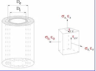
Let the column cross-section be represented by a number of (say N), concentric hollow cylinders with different material properties. This is shown in Fig. 1. Let the dimensions and properties of the nth cylinder be:
rn-1 = internal radius
rn = external radius
En = Elastic modulus
νn = Poisson’s ratio
An = Cross-sectional area.
For the innermost cylinder, n=1, and for the outermost, n=N.
It is assumed that the deformation of the column comprises the deformations of the individual constituent cylinders. The following three loading stages are considered:
1) A unit applied longitudinal load,
Modeling and Analysis of an Elastic Compound
Strut in Axial Compression
Fig. 1: Theoretical modeling of multi-material column as a number of concentric annuli
2) Artificially introduced lateral pressures on the contact surfaces of the cylinders to correct the incompatible radial displacements arising from load case (1) above, and
3) Superposition of above load cases to produce the final state of stress and deformation
The following assumptions are made:
(a) Each cylinder is free to displace radially in isolation. (b) Load is applied and transmitted concentrically along the column.
(c) Shear stresses (τrz and τzr in Fig. 1) on boundary
surfaces may be neglected.
(d) The material of each cylinder is linearly elastic and (e) There is a small but essential cavity of radius ro at the
centre of the column (the cavity can be mathematically set to zero).
B. Representation of stresses and strains
Stresses and strains in the three cylindrical directions (z, r, θ)
are considered (Fig. 1). Since loading is applied in the z-direction, it is assumed that the shear stresses τrz and τzr (on the r-θ and z-θ
surfaces respectively) are negligible. In load case (1), elasticity relationships [3] from elementary mechanics are used to derive the
axial, radial and circumferential stresses,
σ σ σ
nz',
'nr,
n'θ in the nth cylinder due to unit applied axial load. Taking tensile stresses as positive, the stresses for load case (i) can be expressed in matrix form as follows:⎪ ⎪ ⎪ ⎪ ⎪ ⎪
⎭ ⎪ ⎪ ⎪ ⎪ ⎪ ⎪
⎬ ⎫
⎪ ⎪ ⎪ ⎪ ⎪ ⎪
⎩ ⎪ ⎪ ⎪ ⎪ ⎪ ⎪
⎨ ⎧
⎟ ⎠ ⎞ ⎜
⎝
⎛ +
+
−
=
⎪ ⎪ ⎪ ⎪ ⎪ ⎪
⎭ ⎪ ⎪ ⎪ ⎪ ⎪ ⎪
⎬ ⎫
⎪ ⎪ ⎪ ⎪ ⎪ ⎪
⎩ ⎪ ⎪ ⎪ ⎪ ⎪ ⎪
⎨ ⎧
∑
−∑
= = +
0 0 1
1
1
1 1
' ' '
n
i
N
n i
i i i
i n n
n nr nz
E A E
A E
A
θ
σ σ σ
(1)
Therefore the resulting axial, radial and circumferential strains
ε ε ε
nz',
nr',
n'θ in thenth cylinder due to load case (i) are given by:
ε
ε
ε
ν
ν
ν
ν
ν
ν
σ
σ
σ
θ θ
nz
nr
n
n
n n
n n
n n
nz
nr
n
E
'
'
'
'
'
'
⎧
⎨
⎪
⎪
⎪⎪
⎩
⎪
⎪
⎪
⎪
⎫
⎬
⎪
⎪
⎪⎪
⎭
⎪
⎪
⎪
⎪
=
−
−
−
−
−
−
⎡
⎣
⎢
⎢
⎢
⎢
⎢
⎢
⎢
⎢
⎤
⎦
⎥
⎥
⎥
⎥
⎥
⎥
⎥
⎥
⎧
⎨
⎪
⎪
⎪⎪
⎩
⎪
⎪
⎪
⎪
⎫
⎬
⎪
⎪
⎪⎪
⎭
⎪
⎪
⎪
⎪
1
1
1
1
⎪
⎪
⎪
⎪
⎪
⎭
⎪
⎪
⎪
⎪
⎪
⎬
⎫
⎪
⎪
⎪
⎪
⎪
⎩
⎪
⎪
⎪
⎪
⎪
⎨
⎧
⎟
⎠
⎞
⎜
⎝
⎛
+
+
−
⎥
⎥
⎥
⎥
⎥
⎥
⎥
⎥
⎥
⎥
⎥
⎥
⎦
⎤
⎢
⎢
⎢
⎢
⎢
⎢
⎢
⎢
⎢
⎢
⎢
⎢
⎣
⎡
−
−
−
−
−
−
=
∑
∑
+ = − =0
0
1
1
1
1
1
1
1 1 1 N n i i i n i i i n n n n n n n n nE
A
E
A
E
A
E
ν
ν
ν
ν
ν
ν
…(2b)In load case (ii), let contact pressures pn-1 and pn be imposed on
the inner and outer surfaces of the nth cylinder. For radial force
equilibrium, the contact pressure on the outer surface of the (n-1)th cylinder must equal pn-1. Similarly the pressure on the
inner surface of the (n+1)th next cylinder must equal pn. There is
no pressure on the inner surface of the first cylinder as well as on the outer surface of the last cylinder.
The stresses induced at any radial co-ordinate r (measured
from the centre of the column) within the nth cylinder, may be
derived from established formulae from the theory of “thick cylinders” [4]. Hence the axial, radial and circumferential stresses
σ σ σ
''nz,
nr'',
n''θ in thenth cylinder for load case (ii), which now
vary with radial distance, are given by:
⎪
⎭
⎪
⎬
⎫
⎪
⎩
⎪
⎨
⎧
+
−
+
−
=
⎪
⎭
⎪
⎬
⎫
⎪
⎩
⎪
⎨
⎧
− − n n n n n n n n n nr nzC
p
A
p
B
p
A
p
1 1 '' '' ''0
θσ
σ
σ
(3a) where ⎪ ⎪ ⎪ ⎪ ⎭ ⎪⎪ ⎪ ⎪ ⎬ ⎫ ⎟⎟ ⎠ ⎞ ⎜⎜ ⎝ ⎛ + ⎟⎟ ⎠ ⎞ ⎜⎜ ⎝ ⎛ − = ⎟⎟ ⎠ ⎞ ⎜⎜ ⎝ ⎛ − ⎟⎟ ⎠ ⎞ ⎜⎜ ⎝ ⎛ − = ⎟⎟ ⎠ ⎞ ⎜⎜ ⎝ ⎛ − ⎟⎟ ⎠ ⎞ ⎜⎜ ⎝ ⎛ − = − − − − − − 2 2 1 2 1 2 2 2 2 1 2 1 2 2 2 2 2 1 2 2 1 1 1 1 r r r r r C r r r r r B r r r r r A n n n n n n n n n n n n n n n (3b)The ensuing strains
ε ε ε
nz nr nθ''
,
'',
'' are again given in terms of the stresses and elastic constants as follows:ε
ε
ε
ν
ν
ν
ν
ν
ν
σ
σ
σ
θ θ nz nr n n n n n n n n nz nr nE
'' '' '' '' '' ''⎧
⎨
⎪
⎪
⎪⎪
⎩
⎪
⎪
⎪
⎪
⎫
⎬
⎪
⎪
⎪⎪
⎭
⎪
⎪
⎪
⎪
=
−
−
−
−
−
−
⎡
⎣
⎢
⎢
⎢
⎢
⎢
⎢
⎢
⎢
⎤
⎦
⎥
⎥
⎥
⎥
⎥
⎥
⎥
⎥
⎧
⎨
⎪
⎪
⎪⎪
⎩
⎪
⎪
⎪
⎪
⎫
⎬
⎪
⎪
⎪⎪
⎭
⎪
⎪
⎪
⎪
1
1
1
1
(4)⎪
⎭
⎪
⎬
⎫
⎪
⎩
⎪
⎨
⎧
+
−
+
−
⎥
⎥
⎥
⎦
⎤
⎢
⎢
⎢
⎣
⎡
−
−
−
−
−
−
=
− − n n n n n n n n n n n n n n nC
p
A
p
B
p
A
p
E
1 10
1
1
1
1
ν
ν
ν
ν
ν
ν
(5)The stresses and strains in load cases (i) and (ii) can be superimposed, since the problem is assumed to be linearly elastic. So the final stresses1
σ σ σ
nz,
nr,
nθ for the nth cylinder aredefined as follows:
⎪ ⎪ ⎪ ⎪ ⎭ ⎪⎪ ⎪ ⎪ ⎬ ⎫ ⎪ ⎪ ⎪ ⎪ ⎩ ⎪⎪ ⎪ ⎪ ⎨ ⎧ + − + − ⎟ ⎠ ⎞ ⎜ ⎝ ⎛ + + − = ⎪ ⎪ ⎪ ⎭ ⎪⎪ ⎪ ⎬ ⎫ ⎪ ⎪ ⎪ ⎩ ⎪⎪ ⎪ ⎨ ⎧ + ⎪ ⎪ ⎪ ⎭ ⎪⎪ ⎪ ⎬ ⎫ ⎪ ⎪ ⎪ ⎩ ⎪⎪ ⎪ ⎨ ⎧ = ⎪ ⎪ ⎪ ⎭ ⎪⎪ ⎪ ⎬ ⎫ ⎪ ⎪ ⎪ ⎩ ⎪⎪ ⎪ ⎨ ⎧ − − + = − =
∑
∑
n n n n n n n n N n i i i n i i i n n n nr nz n nr nz n nr nz C p A p B p A p E A E A E A 1 1 1 1 1 '' '' '' ' ' ' 1 1 θ θ θ σ σ σ σ σ σ σ σ σ (6)Similarly, the final strains
ε ε ε
nz,
nr,
nθin the nth cylinderare given by: ε ε ε ε ε ε ε ε ε
θ θ θ
nz nr n nz nr n nz nr n ⎧ ⎨ ⎪ ⎪ ⎪⎪ ⎩ ⎪ ⎪ ⎪ ⎪ ⎫ ⎬ ⎪ ⎪ ⎪⎪ ⎭ ⎪ ⎪ ⎪ ⎪ = ⎧ ⎨ ⎪ ⎪ ⎪⎪ ⎩ ⎪ ⎪ ⎪ ⎪ ⎫ ⎬ ⎪ ⎪ ⎪⎪ ⎭ ⎪ ⎪ ⎪ ⎪ + ⎧ ⎨ ⎪ ⎪ ⎪⎪ ⎩ ⎪ ⎪ ⎪ ⎪ ⎫ ⎬ ⎪ ⎪ ⎪⎪ ⎭ ⎪ ⎪ ⎪ ⎪ ' ' ' '' '' '' (7)
C. Boundary conditions to be satisfied
The final state of stress and strain may be applied to satisfy the boundary conditions for force equilibrium and displacement compatibility. Once these conditions are satisfied, the cylinders are “assembled” to form the final state of stress and deformation of the column.
1) At the outside surface of the outermost cylinder (i.e the Nth
cylinder), the pressure is atmospheric. Hence the net radial stress there is zero, thus
( )
σ
Nrr=D
=
2
0
(8) where D= column diameter.the radial stress at the outside face of the nth cylinder be
( )
σ
nr outsidewhile that at the inside face of the(n+1)th cylinder
be
(
σ
(n )r)
inside
+1 . For equilibrium, we have ( )
(
σ
n r)
( )
σ
inside nr outside
+1
=
(9) 3) For compatibility of radial displacements at boundaries, theradial displacement of the outer surface of the nth cylinder must
equal the radial displacement of the inner surface of the (n+1)th
cylinder. Hence
( )
u
nr outside=
(
u
(n+1)r)
inside (10)4) Assuming that there is a small cavity at the centre of the column (the radius ro of which can be mathematically set to
zero), the radial stress at the inner surface of the first cylinder is zero, hence
( )
σ
1r r r0
o
=
=
(11)D. Solution of the stresses and strains
Equation 10 may be considered in a slightly different form by expressing boundary radial displacements in terms of circumferential strains. The circumferential strain at the outer surface of the nth cylinder is given by
( )
ε
nθ( )
outside
nr outside
outside
u
r
=
(12) The circumferential strain at the inner surface of the (n+1)thcan be expressed in a similar way. Therefore, the necessary and sufficient condition for displacement compatibility at boundaries is for the corresponding hoop strains to match. In addition, equating hoop strains rather than radial displacements eliminates the need for an integration process. For N number of cylinders, there are (N-1) boundaries. Thus, there will be (N-1) equations of compatibility containing an equal number of unknown radial pressures. These pressures can then be solved if the material properties are known.
III. APPLICATIONOFTHEMODELTOA TRI-ANNULARMATERIAL(STEEL-ENCASED,
REINFORCEDCONCRETECOLUMN)
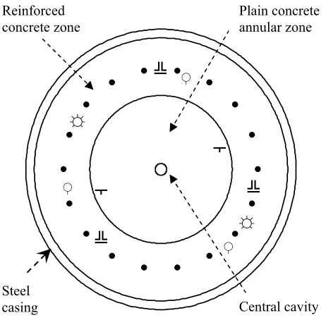
In order to represent accurately the loaded behavior of the short column and to account for the variation of elastic properties with radial distance, a three-annulus configuration was proposed. The steel-encased column is divided into concentric cylinders of three materials as shown in Fig. 2.
(a) an inner core of plain concrete, (b) a zone of reinforced concrete, and (c) the steel casing.
There is also a central cavity which is mathematically set to “zero”. For stress and strain predictions for the column tested without steel casing, there are only two constituent cylinders.
Parallel with the load test, the foregoing method has been used to calculate the deformations of the column.
The elastic modulus of steel and concrete were determined from laboratory tests on samples as 205kN/mm2 and 38kN/mm2
respectively. The Poisson's ratio for steel and plain concrete were taken as 0.3 [5] and 0.2 [6] respectively. The elastic modulus value for the reinforced concrete zone is initially estimated using an "equivalent area" approach, which gives a value of 43kN/mm2. Therefore, trial values of Poisson’s ratio for
reinforced concrete are then taken in the range 0.15-0.4.
Legend: ♀Extensometers, ╩Axial strain gauges,
[image:4.612.325.556.194.421.2]☼Circumferential strain gauges, ┬Radial strain gauges, ●Steel reinforcing bars .
Fig. 2: Representation of the composite steel-encased column by 3 concentric cylinders
Graphs of applied load versus the average axial (average of extensometer value εz1 and vibrating wire strain gauge value εz2),
radial (εr) and circumferential (εθ) strains were plotted from the
results of both tests 1 (tri-material steel-encased column) and 2 (no casing and hence a two-material column). The gradients of the graphs represent strain per unit (1 kN) applied load and are called “normalized strains”. The normalized strain values from all the gauges are presented in Tables 1 (test no. 1) and 2 (test no. 2). The normalized strain values shown have been calculated by linear regression on at least 15 test data points.
Steel casing Reinforced
concrete zone Plain concrete annular zone
Central cavity
☼
☼
╩
╩
╩
┬
┬
♀
♀
Test 1-column with 10mm steel casing εz1 εz2 εr εθ
Cycle 1 Loading
Unloading 33.64 33.17 29.90 27.58
7.95 7.95
8.96 8.53 Cycle 2
Loading
Unloading 29.63 27.38 28.21 27.87 7.95 7.95
7.26 7.26 Cycle 3
Loading
Unloading 29.85 28.88 27.81 26.63 7.78 7.78 7.31 7.74
Mean 30.43 28.00 7.89 7.39
Calculated 31.41 7.74 7.35
Table 1: Measured and calculated strains (x 10-9)
per kN applied load – test no. 1
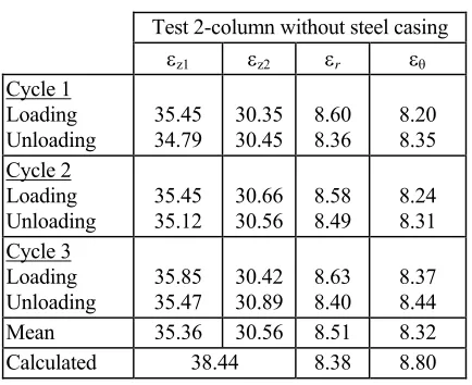
Test 2-column without steel casing εz1 εz2 εr εθ
Cycle 1 Loading Unloading
35.45 34.79
30.35 30.45
8.60 8.36
8.20 8.35 Cycle 2
Loading Unloading
35.45 35.12
30.66 30.56
8.58 8.49
8.24 8.31 Cycle 3
Loading Unloading
35.85 35.47
30.42 30.89
8.63 8.40
8.37 8.44
Mean 35.36 30.56 8.51 8.32
[image:5.612.68.280.73.244.2]Calculated 38.44 8.38 8.80
Table 2: Measured and calculated strains (x 10-9)
per kN applied load – test no. 2
A back analysis process was devised to assess the elastic constants from actual measured strains. The procedure involved determining the influence of selected E and ν values, of the plain and reinforced concrete annuli, on the predicted axial, radial and circumferential strains. In all trial cases, the following values were kept constant: {Es=205,000 N/mm2, νs=0.3, νc=0.2} subscripts s
and c refer to steel and concrete annuli respectively. Various
incremental values of the elastic constants Ec, Eb and νb (subscript b refers to the reinforced concrete annulus) were input into a
purpose written computer program so that stresses and strains could be generated at required increments of radius. It was also imperative to generate the strain values at radial co-ordinates corresponding to the locations of the embedded strain gauges.
The results of this parametric study are summarized in Table 3, which represents the closest match between calculated and measured strain values in all three directions. The measured strains are compared with the theoretically calculated strains
listed at the bottom of the Tables 1 and 2. It is seen that the predicted strains are accurate to within 5% of the measured values and are remarkably consistent throughout.
Constituent material Elastic modulus (kN/mm2)
Poisson’s ratio Steel casing
(r=450-460mm)
205 0.30 Stiffened concrete
zone (r=253-450mm)
42 0.25 Plain concrete core
(r=0-253 mm)
[image:5.612.65.282.284.461.2]38 0.20
Table 3: Appropriate values of E and ν for constituent materials of the test column
IV. CONCLUSIONS
A mathematical model was successfully developed for elastic analysis of a compound column comprising any number annuli having different elastic parameters. Using the model, the material characteristics of the composite reinforced concrete short column were assessed accurately. The stiffening effect of steel on concrete has been realistically assessed by projecting the effective elastic modulus and Poisson’s ratio of the reinforced zone of concrete at a given cross-section. The validity of the model was demonstrated by comparing predicted strains with measured values in three mutually perpendicular directions. An excellent agreement, to within 5% was observed between the measured and the predicted strain values at several locations. The results indicate the following:
a) The change in material properties due to reinforcing of concrete was found to affect the effective Poisson’s ratio more than the Young’s modulus.
b) For a specific amount of reinforcement, it was found that the Poisson’s ratio of concrete increased by 25% whilst the Young’s modulus increased by 10.5%.
c) There was demonstrated evidence that the elastic constants for plain concrete were position sensitive, which support previous observations by other researchers. The evidence arose from the fact that lower strain values were recorded near the central axis of the column. This suggested that there was compression of concrete centrally.
ACKNOWLEDGMENT
REFERENCES
[1] S. A. Klink, “Actual Elastic Modulus of Concrete”, Technical Paper, American Concrete Institute - A.C.I. Journal. 82-54, 1985, pp630-633. [2] S. A. Klink, “Actual Elastic Modulus of Concrete”, Technical Paper,
American Concrete Institute - A.C.I. Journal. 82-54, 1985, pp813-817. [3] S. P. Timoshenko, and J. M. Gere, “Mechanics of materials”, D.Van
Nostrand Co., 1972, pp19-20.
[4] E. P. Popov, “Mechanics of materials”, 2nd Edition, Prentice- Hall Inc., 1976, pp562.
[5] British Standards Institution, “BS5950: 1990, Part 1 - Structural Use of Steelwork in Buildings”, 1990. Milton Keynes, England.