A thesis
for the Degree of Doctor of
Philosophy in Mechanical Engineering at the
University of
Canterb~ry,Christchurch,New Zealand
by
Pharo Duc Truong
To Nga
ACKNOWLEDGEMENTS
I am grateful to my supervisor, Professor H. McCallion, for his patient guidance and lavish encouragements.
I also extend my gratitude to Professor D.C. Stevenson for his permission to use the Departmental facilities; to Drs S. Naguleswaran and K. Whybrew for their active interest in my work; to Messrs J.S. Smaill, H.J. Anink, O. Bolt, J.G. Hodge, G.R. Johnson, E.D. Retallick, and M.E. Webb for their help with the computing, electronic,
ABSTRACT
This thesis presents the analysis, design and development of aids for robotic assembly_ The purpose of these aids is to extend the scope of low-cost industrial robots to the terminal
aligning and insertion phases in the assembly of discrete components. Following a brief survey of existing aids, several novel aids are investigated. These have been divided into two distinct
categories: the 'active' category, suitable for the aligning phase and based on the conscious feedback of touch or force information arising from mechanical contact between the components during assembly, and the 'passive' category, suitable for the insertion phase and based on the implicit, direct, use of such information.
An in-depth treatment of the fundamental principles of active feedback technique forms a major section of the thesis. This is followed by a section on the hardware developed for implementing these techniques. The final section covers passive assembly and describes a simple and effective passive-assembly device.
CHAPTER PAGE 1 1. 2. 3. INTRODUCTION
A SURVEY OF MECHANISED ASSEMBLY 4
4 4 5 6 7 7 2.1 2.2 2.3
OPEN-LOOP ASSEMBLY SYSTEMS 2.1.1 Description
2.1.2 Principles 2.1.3 Discussion
CLOSED-LOOP ASSEMBLY SYSTEMS 2.2.1 Description
2.2.1.1 Assembly systems with contact sensing 7 2.2.1.2 Assembly systems with 'non-contact 11
2.2.1.3 Integrated assembly systems 15
2.2.2 Principles 2.2.3 Discussion SUMMARY
19 21 23
ON FEEDBACK TECHNIQUES 25
25 26 26 30 35 35 37 3.1 3.2 3.3
SENSOR AND ERROR SPACES CURRENT SENSING TECHNIQUES 3.2.1 Contact sensing 3.2.2 Non-contact sensing 3.2.3 Integrated sensing 3.2.4 Discussion
BILATERAL CONTACT SENSING
3.3.1 Principle 38
3.3.2 A family of bilateral contact sensing techniques 39 3.3.2.1 Force-force
3.3.2.2 Touch-force
44
4.
5.
3.4
3.3.2.3 Force-touch sensing 3.3.2.4 Touch-touch sensing 3.3.3 Discussion
SUMMARY
BILATERAL FEEDBACK: A SPECIAL CASE AND A GENERAL THEOREM 4.1 FORCE-FORCE SENSING
4.2
4.3
4.1.1 The Rotation Matrix [R] 4.1.1.1 First possibility 4.1.1.2 Second possibility 4.1.2 The Translation vector t 4.1.3 Discussion
4.1.3.1 Small misalignments 4.1.3.2 Arbitrary misalignments BILATERAL SENSING : A KINEMATIC PERSPECTIVE 4.2.1
4.2.2
SUMMARY
Kinematic Models
4.2.1.1 Touch-force sensing 4.2.1.2 Force-touch sensing 4.2.1.3 Touch-touch sensing Discussion
4.2.2.1 Synthesis of bilateral techniques 4.2.2.2 A theorem on bilateral sensing
THE KINEMATICS OF A COMPUTER-DRIVEN ASSEMBLY MACHINE 5.1
5.2
HARDWARE DESCRIPTION KINEMATIC ANALYSIS
5.2.1 Degree of Freedom and Connectivity 5.2.1.1 Degree of freedom
5.2.1.2 Connectivity
5.2.2 Platform-base Location and Parameters of the
Work Table 96
5.3
5.4
5.2.3 Parameters of the Work Table and Platform-Base Location
5.2.3.1 Closure and constraint equations 5.2.3.2 Numerical solution
PATH SYNTHESIS SUMMARY
6. A COMPLIANT WRIST FOR AN ASSEMBLY ROBOT 6.1 HARDWARE DESCRIPTION
6.2 KINEMATIC ANALYSIS
6.2.1 Degrees of Freedom and Connectivity 6.2.1.1 Degrees of freedom
6.2.1.2 Connectivity 6.2.2 Compatibility Matrix 6.3 STRUCTURAL ANALYSIS
6.3.1 Local Stiffness Matrix [s] 6.3.2 Global Stiffness Matrix [S] 6.3.3 Global Flexibility Matrix [C]
6.4 PEG-HOLE INSERTION 6.5 DISCUSSION
6.6 SUMMARY
7.
CONCLUSION APPENDIX A APPENDIX B REFERENCES103 105 107 109 112 113 113 113 113 113 115 115 120 120 121 121 122 130 130 131
136
162
INTRODUCTION
In general, the of two or more mechanical components may conveniently be divided into four phases:
(i) . pick-up phase: the components are collected from their storage areas (bins, magazines, pallets, etc .. );
(ii) transport, or gross-positioning, phase: they are carried to some assembly station and brought into contact with each other;
(iii) aligning, or fine-positioning, phase: their positional errors are reduced and they are taken inside an insertion envelope, a spatial region defined by their geometry.
(iv) fitting, or insertion, phase: their positional errors are completely eliminated and they are driven horne.
Most existing industrial robots can tackle the first two simple, pick-and-place This study is concerned with the design and development of cost-effective devices and techniques which will extend the applicability of these robots to the more intricate aligning and fitting
At the outset, in Chapter 2, the field of assembly mechanisation will be surveyed in order to provide a background for subsequent work. It will be seen that current assembly systems can be grouped according to
whether or not they employ feedback. In non-feedback or open-loop assembly , all the four assembly phases listed above are implemented by
structuring the assembly environment and observing high dimensional and positional accuracy. These systems are efficient, but also
On the other hand, feedback or closed-loop systems show real potentialities for batch production. Frequently, in these systems programmable robots guided by sophisticated visual and tactile sensors are employed to execute phases (i), (iii) and (iv). As these systems can perceive and interact with their environments, they require a much lower degree of environmental structuring and achieve a much higher of flexibility than do open-loop systems. In the present state of the art, however, most closed-loop assembly systems are still relatively slow, expensive and capable of performing only simple and artificial tasks.
From the survey, i t will be apparent that the viability of batch-oriented robotic assembly hinges on the development of improved feedback techniques. Therefore, in Chapter 3, the study will focus on the problem of feedback. Initially, the threads left in the survey will be picked up with a comparative examination of current sensing techniques, this
time from a more abstract viewpoint. The concept of sensor and error spaces will be introduced, and sensing regarded as a relation between the two spaces. In this light, visual sensing will approximate to a functional relation,
while unilateral contact sensing will show up as a one-to-many relation. Unilateral contact sensing, the only form of contact sensing developed to date, involves obtaining feedback information from a single array of sensors fixed to either a robot or a work table. I t will be shown that contact sensing can theoretically be made functional if bilateral
information is extracted from two sensor arrays, one fixed to the robot and the other to the work table. The Chapter will close with the description of a family of feedback techniques based on this bilateral principle
Work on bilateral feedback will continue in Chapter 4 where detailed examples will be provided to illustrate both the theoretical and cal facets of selected bilateral techniques. It will be shown that in order to
of positioning errors.
Because in most assembly operations the robot has to perform gross
material-handling tasks involving large and swift movements, i t seems al that the finer corrective steps be carried out the work table. To
achieve high positioning accuracy as well as reasonable operating speeds, the work table must be , but also light and manoeuvrable. Chapter 5 will be dev0ted to the analysis of an original computer-controlled work table which possesses all the required characteristics. I t is envisaged that, by using this machine in conjunction with the bilateral techniques proposed in Chapters 3 and 4, even a modestly accurate robot will be able to
the aligning phase without difficulty.
Finally, in Chapter 6, a simple device will be described which, when coupled to such a robot, will help i t succeed also in the insertion phase. The device has been proven on a Unimate 2000B Industrial Robot~ the Unimate, which under normal circumstances can merely position its hand to ±1.2 mm repeatability, has become capable of consistently
cylinders with diametral clearances as fine as 0.02 mm.
MECHANISED ASSEMBLY
The term 'mechanised assembly' is used here in its broad sense to cover the production,
gation of smaller objects.
by machines, of objects from an aggre~
There are two approaches to mechanised assembly. The first approach is to use special~purpose fixed or programmable machines with high accuracy and rigidity and no sensory feedback; the second approach involves flexible robots with sensors, interactive skills and decision-making abilities.
This chapter outlines assembly systems representative of these open-loop and closed-loop approaches and exposes their underlying principles and techniques.
2.1 OPEN LOOP SYSTEMS
2.1.1 Description
A fixed open-loop assembly system [1J [2J is, in general, made up of several work stations. Each station is equipped with workheads and part feeders and is joined to the next station by a conveyor. The assembly operation
is
shared between the work stations, the work being built up on a work carrier and transferred from station to station on the conveyor At each station, the work carrier is firmly andaccurately located by j and fixtures while workheads perform part placing and fastening or inspection tasks. Workheads may be supplied with either magazined or individual parts from hopper-feeding and orienting devices.
synchronizes and co-ordinates the various work stations. Therefore,
the system's operating sequence may be
programs stored in the controller's memory.
changed by changing the
To date, many fixed and programmable open-loop assembly systems
have been developed and successfully applied to large and medium-scale
production.
Fixed automatic transfer lines have been dedicated to
the repetitive assembly of one type of item,
such as lamps [5J,
microphones [5J, gear boxes [5J, and water pumps [6J.
Programmable
assembly machines, on the other hand, have been employed for producing
groups of similar items, for example, a family of post office relays [7J,
vehicle locks [8J, or printed-circuit boards [9J.
Finally, programmable assembly systems making extensive use of
current industrial robots have also been investigated.
The most
impressive effort in this direction has been demonstrated by Kawasaki
Heavy Industries whose prototype engine assembly shop features ten
Kawasaki-Unimate robots and a minicomputer for controlling them [lOJ.
There are five work stations, each manned by two robots and equipped
with a work platform, a hydraulic press and the traditional array of
jigs, fixtures and feeding and orienting devices.
In this set up,
mechanisation is only partial as humans have to be employed in two of
the twelve stages forming the complete assembly operation.
2.1.2 principles
and must be accurately located relative to workheads,
(2)workheads
positioning must be precisely repeatable, and (3) the assembly machine
must be highly rigid.
2.1.3
Discussion
The determinate nature of a structured assembly environment is
conducive to high output rates but its stringent requirements on
accuracy have created a heavy reliance on expensive jigs and fixtures.
In consequence, an open-loop assembly system gets so costly that it can
only be used for large-scale production in which a million identical
assemblies, or more, are required per year, over a period of several
years [3J.
The incorporation of programmable controllers which facilitate
minor product changes has extended the scope of open-loop machines to
the domain of medium-scale production.
However, since without
feed-back accurate jigging is still mandatory, even programmable machines
do not seem economical for small-batch assembly [llJ.
Attempts have been made to reduce the environmental structuring
in open-loop systems (and hence their costs) by fitting them with
special assembly aids and thus enabling them to tolerate some degrees
of uncertainty in their environment.
For example, parts need not be
located exactly, if chamfers are present and compliant workheads are
used [12J [13J [14J [ISJ.
Dynamic aids involving random vibration [16],
ordered search [12], or air flow [17] [18J [
have also been reported,
which can correct small initial misalignments between parts and workheads.
sensors which empower it to perceive its environment and cope with any
arbitrary changes ·therein.
2.2
2.2.1
ASSEMBLY SYSTEMS
In general, closed-loop assembly systems are physically very
similar to the programmable machines described in the previous section.
That is, a closed-loop system also employs a programmable controller
(usually a minicomputer) and a number of parts feeding, orienting,
conveying and placing devices.
The distinctive feature of a
closed-loop system is that, here, the controller can modify the system's
behaviour by making real-time decisions based on the environmental
information gathered by the system's feedback sense.
A
closed-loop assembly system can be classified according to the
types of sensing i t uses.
There are currently three types of systems:
(1) those with contact sensing, (2) those with non-contact sensing, and
(3) those with both types of sensing.
2.2.1.1
Contact sensing involves the detection of force, pressure, or
binary contact at the interface between a
and its environment
[20J [21J.
Binary contact (or touch) sensing is the simplest of all contac·t
sensing techniques.
Mechanical microswitches fitted to the hand of
a manipulator are usually the cheapest and most reliable touch sensors,
although magnetic switches [22] [23J and even analogue pressure and
force transducers [24] [25] [26J [27] have also been applied.
emit electric currents when deformed, and graphite cells [3 or con~ ducting polymeric fibres [3 [33] which in resistance under pressure. An original transducer has also been reported, in which the amount of light received by a phototransistor varies directly with the applied pressure [34J. Pressure transducers are usually arranged into a matrix and embedded in some elastic and insulating medium where they act like nerve endings in the human skin.
Force (and moment) sensing can be practised at the fingers [30J, the wrist [25J [26] [35J 6J or other joints of a manipulator [24J [37J [38J, or can be incorporated into a sensing pedestal separate from the manipulator [35] [39J. Rugged and inexpensive strain gauges are perhaps the most popular devices for finger, wrist and pedestal force sensing, but combinations of springs and displacement transducers can also be used for the same purpose [26J [40J [41J. The feedback of joint forces and moments generally involves measuring motor currents or differential hydraulic pressures on the appropriate joint actuators [42J. Although i t is convenient, joint force sensing is an inaccurate method of determining the forces on a manipulator's hand, because of the variability of the manipulator's inertia and the non-uniform fric-tion in the individual joints [20J.
In spite of its apparent simplicity, contact sensing has not been widely applied. So far, the only commercial ass~bly systems equipped with contact sensors are the Hitachi's Hi~T-Hand machines for cylindrical peg-hole insertion tasks and the Olivetti's SIGMA machines for more
general assembly operations.
The Hi-T-Hand Expert-l model [25J, used for the assembly of pistons into cylinders with 20-micron clearances, has a simple pin-board
robot, a cylinder. Both components are then brought together, but the positioning accuracy of the robots is insufficient for direct mating to take place. The main robot corrects the initial piston-cylinder misalignment by moving the piston in the direction in which i t tips when i t contacts the cylinder's mouth. This direction is detected with strain gauges mounted on the compliant wrist of the main robot. When the misalignment becomes sufficiently small, the springs on the main robot's wrist automatically push the piston into the cylinder, and the insertion phase begins. During this phase, the main robot continuously makes small hand displacements based on the sensor's feedback in order to avoid jamming the piston against the cylinder's wall.
The more recently developed Hi-T-Hand Expert-S [23J can assemble end brackets of electric motors into ball bearings with clearances around 5 microns. It is also sequentially controlled and is equipped with only a simple binary switch for contact sensing. with the bearings held firmly in a horizontal plane, the Expert-S performs the assembly by pushing the brackets down until the switch is activated, which
indicates the presence of an obstacle, and then moving them horizontally in a spiral search pattern to dodge the obstacle. The machine may need to alternate several times between pushing and spiralling to com-plete a successful assembly cycle.
feedback information helps the system to
itself and the
com-ponents it assembles, check the progress of an assembly operation,
or compensate for any small positional discrepancies during the
operation.
SIGMA can continuously harness feedback for implementing
search manoeuvres similar to those in the Hi-T-Hands.
In general,
however, it employs feedback in a binary mode for making conditional
tests ("are parts present or absent?", "are dimensions correct or
abnormal?" etc.) and branching to the appropriate sections in its
control program.
Contact sensing assembly has also been investigated by a number
of research institutions including the MIT
Laboratory [44J [4SJ,
the Stanford Research Institute [46J [47J, and the University of
Canterbury [48J [49J.
So far, the emphasis appears to have been in
studying the fundamentals of the assembly process, deriving useful
contact-sensing strategies, and investigating basic part-mating
operations (such as threading a nut onto a bolt or inserting a peg
into a hole).
One of the few experimental contact-sensing
used for more comprehensive assembly work is the Little Robot System
of the MIT Artificial Intelligence Laboratory.
This system has a
computer-controlled arm with Linear-Variable Differential Transformers
it, which usually means moving it in the direction of the sensed forces
and moments.
2.2.1.2
with non-contact sens
Non-contact sensing enables a system to identify and locate
objects, measure their distances to a datum, or simply detect their
presence in, or absence from, a scene, without making mechanical contact
with its environment.
The non-contact detection of objects can be implemented with
proximity sensors.
various types of proximity sensors are
commer-cially available.
These can be grouped into air-jet
devic~sfor
the short range detection of solid objects [51J [52J,
permanent-magnet devices for the short-range detection of ferrous objects;
inductive devices for the short-range detection of metallic objects;
capacitive devices for the short or medium range detection of any
object;
and transmitter-receiver type devices using ultrasonic or
light beams for the short, medium, or long-range detection of any
object [53J.
The distance of a point to a datum can be measured by range
finders.
There are three major range-finding schemes [32J:
the
first is based on transmitting laser or sound
and measuring the
arrival time of the reflected signals [30J [54J [55J, the second, on
sending laser or sound waves and determining the phase shifts of the
reflected signals [56J [57], and the third, on transmitting continuous
frequency-modulated waves and measuring the instantaneous differences
between the frequencies of the transmitted and received signalS
[S8J.
photodiodes in a straight line
[59].
An pair of arrays used in conjunction with a moving scene (e.g. objects on a conveyor) can three-dimensional pictures of the scene [60J. The taking of two-dimensional pictures is, in general, performed directly with standard television cameras (vidicon, silicon-vidicon, plumbicon, etc.) [61J or with solid-state diode-matrix cameras (also known as area-array cameras)[59J.
These cameras on a sequential raster-scan mode, a raster comprising up to approximately 415 x 625 elements (pixels) in a standard TV camera andbetween 32 x 32 and 320 x 512 pixels in an area-array camera. Another type of camera is the image-dissector camera which is capable of
measuring light intensities at arbitrarily selected Image dissectors can achieve resolutions higher than 1000 x 1000 pixels [62J.
Assembly which employ non-contact sensing as their sole guidance method have been mostly confined to artificial research environments. In assembly research, i t is the third category of non-contact sensing, namely, visual imaging, which has received the most attention. To illustrate visual feedback
four experimental systems are now described.
and its potential, They are (1) The
Nottingham SIRCH general-purpose assembly machine, (2) the Mitsubishi motor-brush insertion robot, (3) the General Motors' wheel mounting system, and (4) the Hitachi Central Research Laboratory's intelligent robot.
by sampling the brightness of the scene at a fixed number of points,
converting the brightness values into binary data and storing them in
the computer memory.
Second, i t spatially differentiates the stored
image and reduces it
to an outline 'diagram' in which edges are
represented by l's and everything else by D's.
Third, it chains the
edges into closed contours and calculates the areas, perimeters, and
centroid co-ordinates of the objects enclosed by the contours.
Fourth,
with these statistics, i t tentatively identifies the object to be
picked up, moves the eye-hand assembly to a position above the object's
centroid and 'zooms in' on the object.
Fifth, it takes a close-up
picture of the object and repeats the outlining and edge-tracing
algorithms to obtain more accurate measurements of the object's
features including its area, perimeter, and centroid co-ordinates,
,
the number of holes in the object, the sizes and locations of the holes,
and the polar co-ordinates of points on the object's periphery.
Finally, using these new feature measurements, i t decides whether the
object under scrutiny is the desired object.
If so, i t computes the
co-ordinates of the point from which the object is to be picked up and
makes successive moves to reach the pick-Up location where it selects
the appropriate hand and acquires the object.
otherwise the machine
backs off and chooses an alternative object for examination.
place it in the inserting machine, and remove the brush holder when
four brushes have been inserted.
position measurements are made by
displacing the camera and analysing the parallax which results from
viewing the scene (a brush) from two separate stations.
Orientation
measurements are made by rotating the camera in a prescribed sequence
until the observed image aligns with an internally stored image.
The General Motors' experimental system for mounting wheels onto
automobile hubs [66J has a manipulator, a hub supporter, a TV camera,
and a computer.
At the beginning of an assembly operation, the
experimenter roughly locates a hub on the supporter and slips a wheel
into the manipulator's hand.
The camera then takes a picture of the
hub and processes the picture to determine the hub's centre and
orientation.
While the processing takes place, the manipulator brings
the wheel into the field of view of the camera.
Next, the picture of
the wheel is taken and its centre and orientation are found.
The
displacements between the hub's studs and the wheel's corresponding
stud holes are calculated and the results fed to the manipulator which
then makes appropriate movements to mount the wheel onto the hub.
The
pictures are always taken in a plane perpendicular to the axis of the
hub (or the wheel) so that the input patterns always assume flat,
sym-metrical, circular shapes.
Owing to this circular symmetry, the
algorithms for finding the hub's (or wheel's) centre and orientation
can make use of efficient signal-processing techniques (peak detection,
thresholding. and convolution filtering) instead of the tedious visual
recognition procedures described above.
three-dimensional objects from plan drawings. With one of the cameras, i t examines the drawings then deduces the three-dimensional structures of the objects, breaks the objects into their component parts and formulates assembly strategies. with the other camera, i t looks at the real placed randomly on a table, identifies the required parts, and makes decisions on how to manipulate these parts to produce the objects in the drawings. Object recognition is done by spatially differentiating the camera pictures to obtain sharp out-lines, fitting segments onto the outlines and extracting the geometric features of the resulting patterns. Drawings understanding is achieved by having a pre-programmed set of rules which enable the robot to treason' like humans do when they engineering drawings.
2.2.1.3 Integrated assembly systems
Integrated assembly systems are assembly with both contact and non-contact sensing. The sensors found in integrated systems are, in essence, the same as those already described in conjunction with contact-sensing and non-contact-sensing assembly systems. In general, non-contact sensors (TV cameras, etc.) are used for global sensing with coarse resolution while contact sensors (binary touch, pressure, or force transducers) are for local sensing and finer resolution.
them with an impact wrench.
Other integrated assembly systems include the experimental
systems built at the university of Edinburgh, IBM, Stanford University
and Hitachi Central Research Laboratory.
The Edinburgh versatile assembly equipment consists of a movable
table, a mechanical hand with force sensors, and two TV cameras, all
connected to a supervisory computer
[3rJ.
This system has been taught
to put rings onto pegs and construct simple devices such as a toy car
and a toy ship [69J.
Teaching is by showing the parts to be assembled
to one of the cameras and 'leading' the hand through the layout and
assembly motions.
During this process, the machine creates internal
models (or hierarchical descriptions) of the parts and memorizes the
assembly sequence.
The parts are subsequently dumped in a heap on
the table.
The machine breaks the heap, recognizes each part by
matching its structure with one of the internal models and lays it
out in its standard position and orientation.
The machine then
assembles the parts, helped by force feedback in the final fitting
stage.
Force feedback is used to implement searches as in the Hitachi
and Olivetti systems already described.
The IBM's experimental assembly set-up comprises a robot with
force, touch, and proximity sensors, a work table, and a supervisory
computer system
[70J.
There are also provisions for equipping the
robot with a comprehensive array of tactile, visual and acoustic
range-imaging devices
[30J.
The set-up is intended for the class of
20-part typewriter sub-assembly that includes two screws and a
Again, touch and force feedback is used
to implement blind
searches, although novel work has also been done on using force
feed-back for directly measuring the position and orien·tation of the
com-ponents to be assembled [72J.
At Stanford University,
a programmable assembly system has been
developed which incorporates a robot (two, in some experiments) with
touch sensors and joint force transducers, a TV camera, a work station
with simple fixtures and tools, and a pair of control computers [27]
[38J.
The system has been used for a variety of tasks, including the
assembly of a pencil sharpener, a door hinge and an automobile water
pump.
The judicious integration of the different sensory modalities
is well illustrated by the water pump assembly operation
[39J,
A
water pump consists of a base, a gasket, a top (including a rotor),
and screws.
First, with the TV camera, the robot roughly locates the
base and then grasps it accurately, guided by touch sensors'mounted
between the robot's fingers.
Next, the robot places the base in its
standard position and orientation against fixed aligning blocks
Using
force feedback, the robot searches for two of the screw holes in the
base and inserts guide pins into them.
It then places the gasket on
the base and visually inspects the gasket's position.
Finally, it mounts
the pump top onto the base, withdraws the guide pins, and secures the top
to the base by means of the screws.
Force feedback enables the robot to
control the torque it applies when screwing and to check that the rotor
can turn freely after the screws have been inserted.
and two control computers [73] [74].
This equipment has been
programmed to assemble a vacuum cleaner consisting of a filter unit,
a motor unit and a dust case.
The assembly operation has been
divided into six stages.
First, from a heap of identical filter
units, that unit which can be most easily picked is recognised by the
visual system using one of the stationary overhead (vertical) cameras
which also determines its macroscopic position.
SENSOR arm then
approaches this position and, with its movable 'eye', precisely
locates the filter's rim.
This information enables the arm to pick
up the filter unit by the rim, the final pick-Up steps being guided
by touch sensors in the arm's extremities.
Second, with the
assistance of POWER arm, SENSOR arm finds a stable and convenient
location in the centre of the filter unit and regrasps it there.
This
unusual handling operation involves touch sensing in alternate arms.
Third, POWER arm picks up the dust case and carries it to the assembly
area.
There, POWER arm holds the case, and SENSOR arm inserts the
filter unit into it.
During insertion, information on the state of
contact between these two components is relayed to the active SENSOR
arm by means of contact sensors in the now-passive POWER arm.
each presses an
over~centrecatch to lock the motor unit to the dust
case.
This locking operation is monitored by force sensors in the
wrists of the arms.
2.2.2
Since a closed-loop assembly machine is endowed with sensors for
perceiving its environment, it no longer needs to
by 'dead
reckoning', but is capable of working in unstructured situations where
there may be variations in the dimensions of the components to be
assembled and uncertainties in their initial alignment and orientation.
Unlike in open-loop assembly machines which have to maintain high
dimensional and positional accuracy by means of structural rigidity
and jigs and fixtures, the principle here is gradually to achieve the
required degree of functional accuracy through intelligent utilization
of sensory information.
The required functional accuracy is determined
by the geometrical properties of the components being assembled.
For
example, if the components are a peg and a hole, the functional accuracy
to be achieved by a positioning system is directly related to the
diameters of the peg and the hole.
In general, contact-sensing assembly machines achieve functional
accuracy through trial and error and heuristic methods.
Consider the
common task of placing a peg (a shaft or a piston) into a hole (the
bore of a
or a cylinder) .
Initially, the sensors (touch, force, or pressure sensors) may
show null
, which indicates that most probably the peg is
be assumed that the peg has not hit a foreign obstacle, some of the
possible states of the peg are (i) it is touching the plane of the
hole entrance at one point, (ii) i t is standing squarely on this plane,
next to the entrance, (iii) i t is contacting the entrance at two points,
(iv) it is on the chamfer, (v) i t is jammed against the hole, and so on.
To determine that state with the maximum likelihood of being the
actual state, various tests based on contact sensing must be performed.
A logical test, applicable when force sensors are used, may be to feel
the resistance of the peg to rocking while still in contact with the
component containing the hole.
If no resistance is felt as the peg is
rocked about any arbitrary axes, state (i) is highly probable.
If the
peg offers equal resistance to rocking about all axes, state (ii) is a
good candidate.
On the other hand, if the peg shows particular
susceptibility to rocking about a single axis, either state (iii), (iv)
or (v) may be true, and so on.
Subsequent motions to be imposed on the peg depend on the outcome
of this and similar tests.
For instance, if it has been decided that
the peg is currently standing next to the hole entrance (whose location
relative to the peg is still unknown), the peg may be set moving in a
spiral to search for this entrance.
Searching halts when a change in
the contact state is detected.
More tests are then performed and
appropriate motions imposed until, after exhaustive attempts, the final
state is reached when the peg is properly seated inside the hole.
and iterating •
On the
in general,
• towards the goal state.
assembly machines with non-contact sensing are,
of 'seeing' the current state of an operation and,
thus, of achieving functional accuracy by deterministic methods.
In
the case of peg-hole assembly, for example, they will measure (using
vision or otherwise) the misalignment between the peg and the hole and
then position the peg accordingly.
All measurements are based on
physical or geometrical principles.
If initially the peg and the block
containing the hole lie on known supporting surfaces (say, the top of a
work table) and if a TV camera is used for sensing, then the 'support
hypothesis' method [75J can be applied to enable the camera to measure
distances and
from a fixed viewing station,
If no a-priori
information is given on the initial peg-hole location, then 'parallax'
(using a moving camera) or 'stereoscopic vision' (using 2 or more cameras)
methods based on the triangulation principle [75J may be necessary to
yield three-dimensional measurements from the observed two-dimensional
images.
Naturally, integrated assembly machines, which have both contact
and non-contact sensing, resort to both trial-and-error and
determin-istic methods to achieve functional accuracy,
Again, in assembling
a peg into a hole, they may at first use visual sensors for measuring
the gross peg-hole misalignment and then touch sensors for guiding the
peg into the hole when vision is occluded or the visual sensors have
reached the limits of their resolving power.
2,2,3 Discussion
and its speed, at least commensurate with that of human workers.
In the present state of the art, i t is
impossible to
meet these conflicting requirements on flexibility, cost, and efficiency,
all at once.
For example, consider contact-sensing assembly.
It
would be relatively easy to construct an
machine with
off-the-shelf sensors,
robot arms, and a simple programmable
con-troller.
The machine could be made quite flexible by minimising its
reliance on complex peripherals (jigs, fixtures, and feeding and
orienting devices).
However, this reduction in environmental
struc-turing would be accompanied by a proportional increase in the ambiguity
of contact information.
In consequence, the required search strategies
would be very elaborate and the machine, extremely slow.
To achieve
realistic speeds, existing contact-sensing
machines have had
to maintain a considerable degree of environmental structuring, thus
sacrificing flexibility and increasing cost.
On the other hand, non-contact-sensing
machines are
inherently flexible by'virtue of their high level of 'consciousness'.
As seen previously, even machines at the lower end of the flexibility
spectrum can recognise randomly placed objects, determine their
loca-tions, pick them up, and assemble them according to pre-taught
sequences.
In the machines developed to date, the key operation,
object recognition, is usually performed by processing large matrices
of visual data
100,000 elements}
low resolving power. In visual systems, this is due to non-linearities in the cameras, their susceptibility to noise from the environment, and digitising errors committed in the processing of The
resolution obtained with most machines is seldom better than a few millimetres and, therefore, unacceptable for the majority of real assembly tasks. This explains why non-contact-sensing assembly is still restricted to laboratory situations where only artificial tasks are performed.
Finally, there are integrated assembly machines, in which the inherent flexibility of non-contact sensing is augmented by the natur-ally high sensitivity of contact sensing. As a result of this logical association, these 'intelligen~ machines are of performing genuine industrial tasks involving the type of tolerances once nego-tiable by humans only_ Although low speed is again a problem with these machines, i t will certainly be overcome when more work is
furthered into developing and refining the current techniqu~s of visual recognition and tactile sensing. What seems at present insuperable is the problem of complexity associated with the high order of intell-igence of these machines. Naturally, complexity means high cost, and this is the ultimate barrier to the widespread application of integrated assembly.
2.3 SUMMARY
The vast domain of mechanised assembly has been surveyed and partitioned into two distinct areas known respectively as open-loop and closed-loop assembly
The viability of
batch~orientedrobotic
hinges
on the feedback techniques employed.
Therefore, in this chapter, we
shall focus our attention onto the problem of feedback.
The chapter begins with a brief comparative examination of
current feedback techniques from an abstract viewpoint.
The concept
of sensor and error spaces is introduced and sensing is regarded as a
relation between the two spaces.
This preamble into the abstract
will lead us to the formulation of a new feedback principle.
A
dis-cussion of a family of feedback techniques based on this principle
concludes the chapter.
3.1 SENSOR AND ERROR SPACES
The sensor space of an assembly machine is defined as the set
of all the possible states of its sensors.
For example, if a machine
employs a binary switch as its only sensing device, its sensor state
is finite and composed of two elements.
If the machine has six binary
switches, the number of elements increases to 2
6
, or 64.
On the other
hand, if the sensors are analogue devices (strain gauges,
photo-transistors, etc.), then the sensor space is theoretically an infinite
set
Each element of a sensor space is a vector whose components
characterise the states of the individual sensors.
The number of
components in a vector can range between I (as in the single-switch
machine) and several thousand (as in a visual robot).
The error space during the assembly of two rigid bodies is
The assembly of two bodies may be regarded as a problem of matching their respective coordinate systems, and sensing, a case of deducing
the systems' misalignments from the states of the sensors involved. That is, sensing (or more correctly, perception) is a relation from sensor space to error space (Fig. 3.la).
A general observation can be made at this point. Ideally, sensing should be an unambiguous procedure, which means that the relation from sensor space to error space should be functional (or that to each element in sensor space there should correspond one and only one element in error space) (Fig.3,lb). As an error-space
element is defined by six independent quantities, ~a~~~~~~~c~o~n~d~l~'~t~i~o~n for functionality is that each element in sensor space has at least six independent co-ordiEates.
3.2 CURRENT SENSING TECHNIQUES
Current techniques have already been described in Chapter 2, in connection with closed-loop assembly In this section, we shall attempt to provide somewhat more formal explanations for their inherent The simple but classical example of peg-hole assembly will sometimes be used to illustrate abstract concepts although these can apply to more general situations. The discussion will follow the pattern of Chapter 2 and will proceed from the simple contact-sensing techniques to the more complex non-contact and integrated techniques.
3.2.1 Contact sensing
In all of the assembly systems that we have reviewed, contact
sensing
sensor
space
error
space
(a)
sensing as a relation
sensor
space
error
space
from a s array during any given phase of an assembly task) .
If, as in some contact-sensing machines [23], the sensor array consists of only one binary switch, then clearly the necessary condition for functionality stated in Section 3.1 is not satisfied. Consequently, contact sensing with a binary switch is a one~to-many relation from sensor space to error space (Fig. 3.2a). In more practical terms, a robot fitted with a simple binary switch cannot uniquely determine the relative location between a part fixed to a work table and another held
in its hand, unless i t uses the switch for performing searches as a blind man does with his cane (like the man, the robot then needs to
combine its touch sense with a sense of position or proprioceptive sense).
In most contact-sensing robots developed to date, the sensor array is a six-degree-of-freedom force (and moment) transducer. A sensor-space vector then consists of six components. However, as we shall now demonstrate, i t still cannot be mapped unequivocally to a counterpart in error space.
First, note that the outputs of a force transducer are continuous, but in some applications they are used simply to signal binary contact events along the different axes of the transducer [26] [38] [69]. For example, while assembling a peg into a hole, a robot often is concerned not with the true contact force and moment vectors on the peg
is clearly not a functional relation (Fig. 3.2b). Again, this means the robot must resort to blind search as i t is unable to pin point the relative location of mating parts with the information derived from a single contact between them.
Finally, in the case of analogue-vector contact sensing where the sensor space is infinite because the reaction forces and moments on
mating parts are recorded as true vector quantities, i t can be shown that each sensor-space element is equivalent in geometric information content to a vector with only five components at the most. The geometric
information content of a sensor-space vector is that part of the vector which can provide clues about the error space. (Geometric information is to be distinguished from stress, deformation, or
information picked up by a sensor array).
types of
To show that a sensor-space vector consisting of a reaction force F (with 3 components) and a reaction moment M (with another 3 components) contains no more than 5 pieces of geometric information, we shall invoke a theo·rem by Poinsot on the reduction of systems of forces and moments
[76] • In essence, the theorem states that, except when F is null, the intrinsic resultant of F and M is a wrench which comprises a force
M
is null, we have a pure couple and hence only three such information
items.
Thus, in practice the number of geometrically significant
compon-ents in a force-moment vector is always less than six.
Again, by
referring to the functionality condition stated in section 3.1, we can
conclude that analogue-vector contact sensing, too, is a one-to-many
relation between sensor and error spaces.
Figure 3.2c illustrates the ambiguity of analogue-vector contact
information and provides justification for blind search in the simple
peg-hole configuration.
3.2.2
Although various forms of non-contact sensing are possible, this
section will only discuss visual sensing, a prevalent form of non-contact
sensing found in existing assembly systems.
It is assumed that a TV
camera is used as the visual organ.
A sensor-space vector then consists
of light intensity measurements taken at all the points in the image
plane of the camera.
First, consider the two-dimensional case where parts are flat and
located on a plane surface whose position and orientation with respect
to the camera are known
sensor
space
; fini.te,
sensor
space
infinite
sensor
error
space'
(a) binary (on tact sensing
infinite
error
space
infinite
subspaces . . .
-(b) binary - vector contact sensing
infini
error
space
(c)
analogue - vector contact sensing
corresponding image point. As the coordinates of image points are given by their positions in a sensor-space vector, the coordinates of object points, and hence the location of the object itself, can be readily determined.
Clearly, if several objects lie on the plane surface in the field of view of the camera, their relative location can be unambiguously deduced from the sensor-space vector. In other words, visual sensing with an ideal T.V. camera in a two-dimensional situation is a functional relation between sensor and error spaces (Fig.3.4a).
A real camera, however, has its image plane divided into a grid pattern with a finite number of image points where the light intensities from an
infinite number of object points are sampled. Thus, there no longer is a one-to-one correspondence between image and object points or a strict
functional relation between sensor-space and error-space vectors. Instead, each image point projects into a small portion of the object plane and each sensor7space vector, into a small subset of the error space (Fig. 3.4b). The size of such an error-space sub-set, or object-plane portion, is directly related to the resolution of the camera.
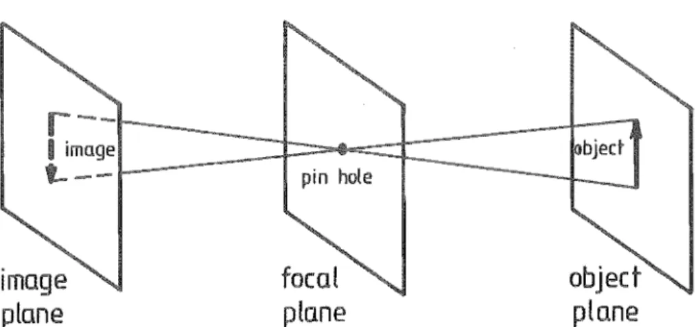
Finally, in three dimensions where objects are not flat or located on a known support, but have thicknesses and may be arbitrarily placed,
Image
plane
peg
+---1( a)
pin hole
focal
pla.ne
FIG 3' 3 PIN HOLE MODEL OF A
CAMERA
hole block
camera
(b) real cam
plane
focal plane
(a) ambiguity in
3D
VISion
camera displacement
( known)
A
(b) triangulation for find
d
Naturally, in an assembly machine using visual feedback alone, this volume must be 'smaller' than that allowed by
assembly to occur.
clearances for direct
3.2.3 Integrated sensing
Where parts with fine clearances are to be mated, force or touch sensing can be combined with visual sensing to achieve the high resolution
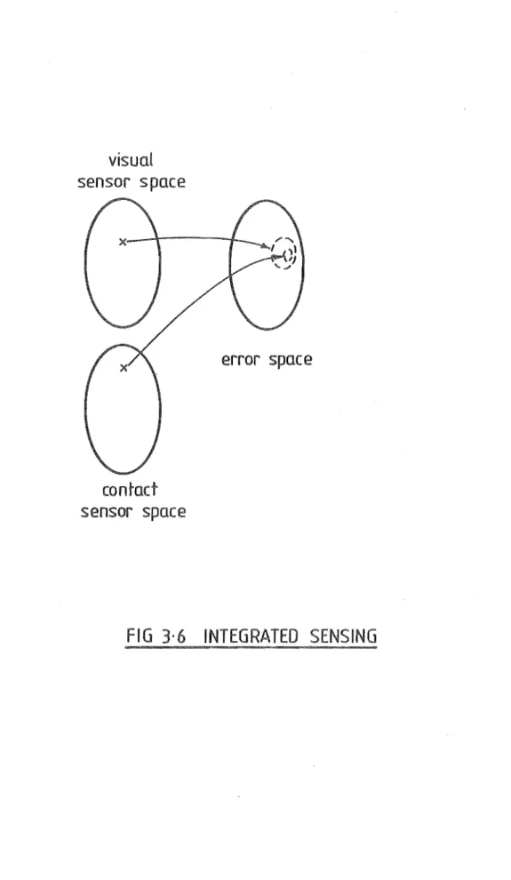
This combination has been termed 'integrated sensing',
AS mentioned in Chapter 2, integrated sensing is typically carried out in two stages, with visual sensing employed in the first stage to reduce the large initial error space to a I smaller'- hyper-volume, and force or touch sensing in the second to implement blind search within this
volume. From Fig. 3.6 i t is obvious that integrated sensing cannot be a functional relation between sensor and error spaces.
3.2.4 Discussion
Thus, for various reasons, none of the sensing s is strictly a functional relation and none can give, in a single step and with complete certainty, the state of relative misalignment of two objects during an assembly operation.
The non-functionality of contact sensing is due to its inherent
visual
sensor space
con~act
sensor space
error space
The of visual sensing on the other hand is mainly caused by the limitations and imperfections of visual hardware. However, since the geometric information content of visual sensing is still
fundamentally complete, functionality can be approached as visual hardware is upgraded. fically, the error-space subset associated with each sensor-space vector will be contracted, and the definition in a visual image, enhanced, if the ratio of image points and corresponding points is increased, either by focussing an existing camera onto a narrowed field of view or by a camera with improved resolution. Although theoretically the image-point-to-obj
limited by the
ratio can tend to 1, in of an image processor to cope
it is with excessive redundant information. (Note that, because only 6 parameters are required to define an error-space vector, a visual-sensor space vector which has several thousand components always contains redundant information. As the resolution of a camera increases, so will the number of components, the amount of redundancy, and hence the time required for sorting out useful geometric information.)
Finally, is a non-functional relation because i t is a nested sequence of two non-functional relations. Integrated sensing
machines can also be as contact-sensing machines in which the size of the total error space is controlled by visual sensing rather than by environmental structuring.
3.3 BILATERAL CONTACT SENSING
Basically, contact sensors are inexpensive and contact sensing, easy to implement. However, i t has been found that unilateral contact sensing must usually be complemented by either visual sensing or environmental structuring to limit the total error space and facilitate blind search. Some of the penalties then incurred are the complexity of artificial vision or the
On the other hand, if con'tact sensing can be complemented by contact sensing, its inherent low cost and simplicity will be retained and the above penalties averted. This is the case with bilateral (or stereo) contact sensing where two arrays of contact sensors are and the information related to contact during the assembly of two ects is extracted simultaneously from their respective arrays.
In this section we shall outline the general pri of bilateral sensing and illustrate i t with examples of a family of bilateral contact sensing techniques.
3,3.1 Principle
Let Al and A2 be two sensor arrays fixed respectively to two rigid bodies Bl and B2 whose relative location :B is to be determined. Clearly, e can be
-B computed from the relative location e of Al and A2 provided e is known.
_A -A
Bilateral sensing is an indirect technique for obtaining :A based on comparing the observations of Al and A2 when these arrays are stimulated by identical world events (e.g. light rays from a point source or contact reactions on Bl and B2 at their mutual interface.)
To appreciate how comparing the observations of Al and can Id :A' consider the special case where the observations of Al coincide with those of
for all world events: i t is obvious that Al and A2 must then coincide, or
o.
More generally, i f ~l and ~2 are the observations of Al and A2 correspond-ing to the Sillne world event W, comparcorrespond-ing ~l and ~2 becomes to
intersecting their respective error-space subsets El and E2 3.7a) . Since by definition El and E2 each contains :A' the intersection of El and E2
denoted by El
n
E2, must also contain
an ideal intersection of and E
2, that is, if this intersection contained only one element ~ the vector e .
-A However, even when
n
E2 contains otherelements in addition to we can still intuitively visualize the possibility of pinpointing e if the intersection of error-space subsets is repeated ad
-A
(Fig 3.7b). In practice, the number of intersections then required is finite and dependent on the exact nature of each intersection.
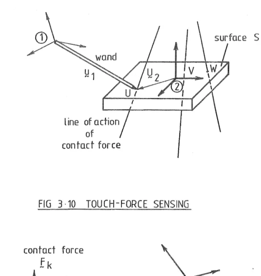
3.3.2 A of bilateral contact sens
---~---~---~---How mUltiple intersections of error-space subsets can yield ~A will now be demonstrated mathematically for cases where both Al and A2 are arrays of contact sensors.
In the following discussion, i t is assumed that is mounted on a robot hand and A2 on a worktable. (Thus body ~ can be the robot hand or a part
thereof and similarly, body
B2
can be the work table or a part thereof.) Let the location of Al relative to some fixed reference be defined by the triad of coordinate axes (~l' ~l' ~l) and the location of A2
,
by (~2' ~2' ~2) as shownin Fig. 3.8. For simplicity we also take (~lf ~lf location of B
I, and (~2f ~2' ~2) , the location of B2·
} as representing the
As mentioned previously, the location of A2 relative to Al is specified by where
t being a translation vector which defines the position of A2 relative to AI' and ~, a rotation 'vector' which defines the orientatiol of relative to AI"
Generally t
Iy}z( 1
L
J
where x, y and z are the coordinates of the origin ofsensor
space
CD
error space
sensor
space
(£)
(a)
the intersedion of error-space subsets
arbitrary
reference
/
joint position sensors
sensor array A 1
body B1
(robot hand
&
pegs)
sensor
array A2
body B2
and r ~C r ~R
Uj
where
¢,
8 andW
are the Euler angles of (X , Y , ~2)~2
~2-relative to (~l' ~l' ~l)'
where 8
,
8 and 8 are the an9les of the elementary x y zrotations R , R and R about the Cartesian axes x y z
~l' ~l and ~l' which, when combined in this order, transform the orientation of Al into that of A
2,
11IvAJ
I
t-' whereA,
l-l and V are the Rodrigues parameterscorrespond-ing to the scorrespond-ingle rotation which transforms the orientation of Al into that of A2
For convenience, we shall not deal with any of these particular forms of r in this Chapter, Instead, we shall be concerned only with finding the general rotation matrix [R] which also completely specifies the orientation of A2 with respect to AI' [R] is a 3x3 orthogonal matrix defined as
[R] - [no
~l
A n. ~J
A ]
~
Eq. 3,0where the column vectors ~i' ~j and ~k are precisely ~2' :2 and ~2 expressed in the (~l' ~l' ~l) coordinate system.
n.,
Ii.
andIi
satisfy the following identities~l ~J . ~k A 2
n.
~l
A 2 n. ~J A n. ~l I 1 A 0 n· ~J
A A
- n x n.
~i ~J
o
which are the orthogonality conditions for [R].
Eq. 3.1 Eq. 3.2 Eq. 3,3
EqS 3.4 to 3.6
Note that once [R] is known, ::E' rand r can be easily derived since
cos ~ cos e cos ljJ
-
cos ~ cos e sin ljJ cos~
sin el
- sin 1> sin ljJ - sin 1> cos ljJsin 1> cos e cos ljJ - sin 1> cos e sin ljJ sin 1> sin
e
[R]
+ cos 1> sin ljJ + cos 1> cos ljJ
- sin e cos ljJ sin e sin ljJ cos e
case case sine sine case case sine case
y z x y z x y z
-
case sine + sine sinex z x z
case sine sine sine sine case sine sine
y z x y z x y z
+ case case
-
sine casex z x z
-
sine sine case case casey x y x y
I
(A
2 _ 2 2 I II + jl
-
\) ) - \) +- Ajl
jl +- A\)
4 2 2
I \) +
- Ajl
I I + I(-A
2 + jl 2-
\) 2 )A
+ -I jl\)[., 2 4 2
I
A
+ I I 2 2,/)
-jl + -
AI)
jl\) I +(-A
-
jl +2 2 4
where I + I (A 2 + jl 2 +
v )
24
We shall now describe four groups of techniques for deriving t and [R] 0
These groups have been arranged according to whether
I - A
I and A2 are both force sensor arrays
2 - A
I is made up of touch sensors, and A2 of force sensors 3 - A
I is made up of force sensors, and A2 of touch sensors
3.3.2.1 Force-force sensing
It is assumed that both the robot hand (body B
l) and the work table (body B
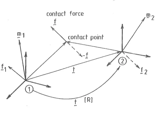
2) are equipped with force sensors (arrays Al and A2) . First, suppose Bl and B2 are in static contact and the forces and moments they mutually exert are picked up by A and A2 as (f
l , ml ) and (f2, m ) . For
1 - - - - 2
equilibrium (see also Fig. 3.9a)
~l
m
+
[R] m-1 -2
[R] ~2
t x f
-1
Eqs 3.7 to 3.9 Eqs, 3.10 to 3.12
Suppose now that the contact forces and moments mutually exerted by Bl
will satisfy the following equilibrium relations
F -1
~l + [R] ~2
- [R] ::2
t x F
-1
Eqs 3.13 to 3.15
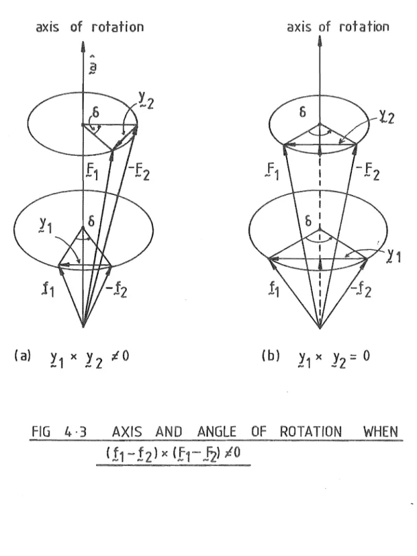
Eqs 3.16 to 3.18 The set of Equations 3.0 to 3.18 is solvable for [R] and t if ~l and :1 are linearly independent. An exact, closed-form solution based on vector algebra exists and will be described in Chapter 4. Another method of finding
[R] and t involves numerical procedures. For example, Brown's algorithm for solving systems of non-linear equations [77] (which will be explained in Chapter 5) can be applied to the set of Equations 3.0 to 3.8 and 3.13, to yield [R]. t can then be obtained from any triplet of linearly-independent equations selected from the set of Equations 3.10 to 3.12 and 3.16 to 3.18.
In Equations 3.13 to 3.18, for simplicity we have assumed that the relative location between Bl and B2 remains constant although the contact