Practical Indoor Localization
using Bluetooth
Master Thesis
Daan Scheerens
January 2012
Supervising committee:
Dr. A. Wombacher
MSc. B.J. Dil
Prof. dr. P.J.M. Havinga
Abstract
Localization is a problem that has been addressed using a variety of technologies. In this thesis the use of Bluetooth for indoor localization is studied. The advantage of this technology over others is that it is pervasively available, is relatively cheap and has a relatively low power consumption. Especially the fact that Bluetooth is integrated in a wide range of mobile devices, makes its use attractive. The question being answered by this thesis is which design of a Bluetooth based localization system works well for indoor environments. The context of the localization system is that of an office building in which the location of employees is tracked. The main contribution of this thesis is a practical evaluation of Bluetooth as a technology for indoor localization.
Received Signal Strength in the inquiry phase of the Bluetooth device discovery protocol has been identified as the most suitable localization measure. This measure, however, has the disadvan-tage that the sample rate is relatively low. Tests have shown that at least one minute is required to collect a sufficient number of samples. Because of the relatively low sample rate, accurate location estimation of moving people is not possible.
To study the localization performance of Bluetooth for indoor environments a number of lo-calization algorithms were tested. These algorithms include: Ecolocation, calibrated and uncali-brated Log-Normal Shadowing model based algorithms and fingerprinting based algorithms. For each algorithm localization accuracy was computed using datasets which were collected in a test environment. Furthermore, the effect of several controllable and uncontrollable parameters on localization accuracy was tested for the algorithms. The controllable parameters that were tested are: number of access points and window size, and the uncontrollable parameters that were tested are: device orientation, device height, transmitter power level and environment structure. An analysis of the effects of these parameters shows that the uncalibrated algorithms are less sensitive to the uncontrollable parameters. These algorithms, however, require more access points to achieve reasonable localization accuracy.
The main conclusion of this thesis is that the uncalibrated localization algorithms are best suitable for indoor localization. This is because of the low impact of the uncontrollable parameters on their localization performance. Which algorithm works the best depends on the number of access points that can detect a target. For 5 access points or less, Ecolocation appears to yield the best location estimates. Otherwise, the uncalibrated Log-Normal Shadowing model based algorithm performs the best.
Acknowledgements
First I would like to take the opportunity to thank my supervisors: Andreas Wombacher, Bram Dil and Paul Havinga. Especially Andreas and Bram have dedicated a lot of their time to support me in the process of the research. I have spent a lot of hours with both Andreas and Bram talking about my progress and how to proceed. Initially Andreas and I came up with a lot of wild and crazy ideas on how to tackle some of the problems faced with indoor localization. Fortunately, Bram got involved, which has probably prevented us from pursuing approaches which would not have been fruitful. It has been a good example though, showing once again that conceptually simple approaches often work best.
A person that I would like to thank in particular is my girlfriend Ingeborgh Kloosterziel. She has given me great support during this research. Apart from a lot of moral support, she has assisted me with most of the data measurements. Also, in the last phase of the research, she supported me by taking care of the less pleasant housekeeping tasks such as cleaning, cooking and doing the dishes, so I could continue writing my thesis. I really appreciate all that she did for me. I would also like to thank my father, Jaap Scheerens, who has been so kind to check the text of my thesis for errors. Furthermore I would like to thank the following people for assisting me with restructuring the layout of the SmartXP lab for the data measurements: Sjon Berghout, Mattijs Jonker, Fiona Klaassen and Alex van Oostrum. Finally I would like to show my gratitude to the people responsible for the SmartXP lab: Egbert Nijland, Alfred de Vries and Berend Jan van der Zwaag, who enabled me to perform my data measurements in the SmartXP lab.
Contents
Abstract i
Acknowledgements iii
Contents v
1 Introduction 1
1.1 Motivation . . . 1
1.2 Problem . . . 2
1.3 Research questions . . . 3
1.4 Contribution . . . 5
1.5 Outline . . . 5
2 Localization basics 7 2.1 Localization problem definition . . . 7
2.2 Signal based localization methods . . . 8
2.2.1 Signal strength based methods . . . 8
2.2.2 Time based methods . . . 9
2.2.3 Radio interferometric localization . . . 10
2.2.4 Event rate based methods . . . 11
2.3 Technologies . . . 11
2.3.1 Dedicated localization technologies . . . 11
2.3.2 Localization enabling technologies . . . 12
2.4 System properties . . . 13
2.5 Current advances . . . 14
3 Context 17 3.1 Use case scenario . . . 17
3.1.1 Requirements . . . 17
3.1.2 Assumptions . . . 18
3.2 Test environment . . . 19
3.2.1 Hardware and infrastructure . . . 19
4 Bluetooth 23 4.1 History . . . 23
4.2 Technology overview . . . 23
4.3 Localization measures . . . 24
4.3.1 Inquiry process based localization . . . 24
4.3.2 Other measures . . . 26
5 Localization parameters 29 5.1 Controllable parameters . . . 29
5.2 Uncontrollable parameters . . . 30
5.2.1 Target device type . . . 30
5.2.2 Target device location and orientation . . . 30
vi CONTENTS
5.2.3 Environment structure and layout . . . 31
5.2.4 Localization problems . . . 31
6 Localization algorithms 33 6.1 Ecolocation . . . 33
6.2 Log-Normal Shadowing model . . . 34
6.2.1 Calibrated localization . . . 35
6.2.2 Uncalibrated localization . . . 38
6.3 Fingerprinting . . . 39
6.3.1 Mean RSS . . . 40
6.3.2 Jensen-Shannon Divergence . . . 41
6.3.3 Inquiry Response Rate . . . 41
6.4 Comparison . . . 42
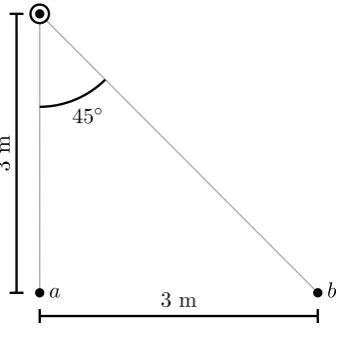
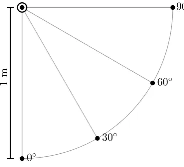
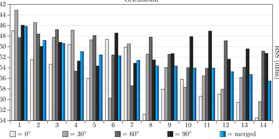
7 Measurements 45 7.1 Antenna orientation . . . 45
7.1.1 Measurement setup for orientation . . . 46
7.1.2 Results . . . 46
7.2 Calibration and evaluation datasets . . . 48
7.2.1 Measurement setup for dataset collection . . . 49
7.2.2 Performance bounds . . . 51
8 Performance evaluation 55 8.1 General performance . . . 55
8.2 Orientation . . . 58
8.3 Environment structure . . . 59
8.4 Device height . . . 61
8.5 Transmitter Power . . . 62
8.6 Number of access points . . . 64
8.7 Window size . . . 65
9 Practical test 69 9.1 Measurement setup . . . 69
9.2 Results . . . 70
10 Conclusions 73 11 Future work 77 Bibliography 79 A Old dataset 83 B Linear regression methods 85 B.1 Ordinary Least Squares . . . 85
B.2 Iteratively Reweighted Least Squares . . . 85
C Dongle orientation measurements 87 C.1 Tested orientations . . . 87
C.2 Results . . . 88
C.3 Consistency test results . . . 88
Chapter 1
Introduction
Navigation is probably among one of the oldest problems faced by the human species. The early hunters and gatherers, after having successfully chased their prey, needed to find a way back to their camp. Those people had acquired some remarkable skills in finding their way through the wilderness. Such skills have now long been forgotten and only a few people remain that are familiar with them. One way people were able to navigate was using the orientation of stars on the night sky. This method has proven to be very successful at night and in the absence of clouds. However, during the day this method was useless and we are all well aware of the fact that we cannot rely on clear skies. The invention of the compass was a big improvement, since it allowed people to navigate at anytime and anywhere.
Nowadays we have the luxury of electronics and the Global Positioning System (GPS) has become the method of choice for navigation. In fact with our increased mobility navigation is still one of the tasks we perform regularly. Some even need to do so on a daily basis. GPS has greatly simplified our navigation problem and its popularity can be seen from the many car navigation systems that are being used. People using printed maps are becoming rarer every day.
Advances in (computer) electronics and the dynamic nature of the modern societies have also led to a desire for navigation on a smaller scale. More generally there is an increased interest in location aware services. Such services adapt their functionality and processes based on their location. For example one can think of an application running on mobile phones that shows weather information for the area where the devices are located. While this application does not require a very fine location estimate, there are a lot of applications and services that would benefit from a location estimate with sub-meter accuracy. For rescue squats like fire fighters and the police, being able to locate persons in a building with an accuracy of 1 meter could make a difference between life or death. But also in less extreme cases would an accurate location estimate be really useful, for example finding your colleague in a big office building.
This thesis is about localization using Bluetooth technology in indoor environments. Local-ization can be defined as the process of finding the location of an object or person. LocalLocal-ization is thus the basis for navigation and other location aware services. Bluetooth is simply one of the many technologies that could be used for localization.
1.1
Motivation
Localization was earlier defined as the process of finding the location of an object or person. The location is always relative to some user defined space. For GPS this space is earth and each GPS coordinate uniquely defines a location on earth. Other localization system operate on a local space such as a city or building. This thesis focuses on the latter. The reason for that is quite simple: Bluetooth has a limited range. Using Bluetooth technology for a larger scale would be cost ineffective and other technologies would be more appropriate. On the other hand localization technologies that operate on a large scale are not suitable for smaller scale environments like buildings. GPS for example cannot be used indoor, because a GPS device requires a line of sight to at least four satellites, which is usually not possible in indoor environments.
Bluetooth is actually not a technology that is designed to be used for object localization.
2 CHAPTER 1. INTRODUCTION
In fact there are other technologies available which have been explicitly designed for accurate indoor localization. Some of these technologies are able to achieve high location estimates with a high degree of accuracy. This raises the question what the advantage is of Bluetooth over other technologies. Even though this technology is not designed to support object localization it does have advantages over other technologies, which are:
• Bluetooth is pervasively available. Most mobile devices, like cell phones, PDAs and laptops are already equipped with a Bluetooth module. People carrying such a device already ‘wear’ all the hardware which is required to localize them. Many other indoor localization systems, however, require the person or object being localized to wear a special badge. This badge contains the hardware which interacts with other parts of the localization system to estimate the location of the target. Using Bluetooth instead of specialized localization technology thus has the advantage that the person being localized does not need to be equipped with additional hardware.
• Bluetooth is relatively cheap. The widespread adoption of Bluetooth in a large variety of devices has resulted in the availability of Bluetooth chips at low prices. Building a localization system using Bluetooth technology can thus be done using low price, off the shelf hardware. Also, since the system does not need to use tracking badges the only hardware costs stem from the Bluetooth sensor network. Commercial localization systems are rather expensive compared to the costs of building a Bluetooth localization system.
• The power consumption of Bluetooth modules is relatively low. The main purpose of Blue-tooth is to be a replacement for short distance wired data transfer. Hence, it does not require a large transmission range and the Bluetooth signals are transmitted at low power levels. Since Bluetooth is used in a lot of mobile devices, manufacturers have also put effort in pro-ducing Bluetooth chips with even lower power consumption. As a result Bluetooth puts less of a penalty on battery life compared to other wireless technologies, like Wi-Fi for example.
Despite the advantages of Bluetooth, there are also some disadvantages. The fact that it has not been designed for object localization means that it will not be able to achieve the same accuracy as the technologies that have specifically been designed for localization. We also found that Bluetooth is not suitable for real time target tracking. Nonetheless, the advantages mentioned earlier make Bluetooth an interesting technology for indoor localization. Mainly because it can be realized with simple, off the shelf hardware, at a low cost and without having to bother people with badges that they should wear.
1.2
Problem
The practical usefulness of a localization system depends on the context in which it will be used. In this thesis the context is that of indoor environments. More specifically the context is defined by a use case scenario for an office building, in which we would like to track to location of people inside the office. To evaluate whether a localization system is useful for a particular context, 5 system properties were identified. These properties are: accuracy, responsiveness, calibration effort, adaptiveness and operational constraints. A full description of these properties is given in section 2.4.
1.3. RESEARCH QUESTIONS 3
of these changes may negatively affect the accuracy of the localization system. To cope with these changes the localization system needs to adapt automatically, be recalibrated or both. Ideally the system adapts fully autonomously so no recalibration is required. If the calibration requires quite an effort, having to repeat this process over and over, quickly makes the maintenance of the system too cumbersome. Finally the operational constraints of the system should be such that they do not hinder the people in their activities.
In short this thesis is about the design of Bluetooth based localization system to track the location of employees inside an office building. The desired system has at least an accuracy of 5 meters, is able to adapt to changes in the environment, requires minimal calibration effort and does not constrain the activities of the employees. The system does not need to accurately estimate the location of moving people, but it does for people who are in a stationary position.
1.3
Research questions
Based on the problem description, presented in the previous section, we would like to answer to the following main research question:
Which Bluetooth based localization system design works well for indoor environ-ments?
Note that the term ‘well’ may be a bit ambiguous. What is meant with this term is that the system is compliant with a set of minimal requirements. These requirements are specified in a later section. To answer the main question, research has been divided in the following sub ques-tions:
1. Which localization measures are best suitable within the context?
Bluetooth supports a number of different measures that can be used for localization. Each of these measures has its own advantages and disadvantages. These advantages and disad-vantages need to be weighted with respect to the context in which the localization system is to be applied. This question is answered in section 4.3.
2. What are the parameters that influence localization performance?
Localization performance, primarily accuracy, is affected by several controllable and uncon-trollable parameters. These parameters need to identified in order to evaluate their impact on performance. This question is answered in chapter 5.
3. Which localization methods will be evaluated?
Estimating the location of a target can be done using multiple methods. In fact, a huge number of methods exist, although most of them are variations of one another. However, each method has its own characteristics and not every method performs equally well under the same conditions. Therefore a selection needs to be made of different localization meth-ods, which will be used to evaluate localization performance. This question is answered in chapter 6.
4. What is the optimal orientation between target device and access point sensors?
4 CHAPTER 1. INTRODUCTION
5. What is the maximum localization accuracy that can be achieved?
The spatial deployment of sensors has influence on the localization results. With this infor-mation it is possible to compute a lower bound on localization accuracy for the setup used to evaluate the performance of various localization methods. This question is answered in section 7.2.2.
6. How do the localization parameters affect localization performance?
There are a number of different parameters which have an influence on the location estimates. Some of these are controllable, i.e. they can be set manually to a fixed state and are known to the system. Others are uncontrollable, meaning they are variable and unknown to the system. To find a system design that works well for indoor localization, the effect of these parameters on localization performance needs to be evaluated. This question is answered in section 8 and is divided into the following sub questions for each localization parameter:
(a) To what extent does unknown device orientation affect localization accu-racy?
In a practical application of the localization system, there is no control over the relative orientation between target devices and the access point sensors. We therefore would like to know how this affects localization accuracy, to see if this restricts the applicability of the system. This question is answered in section 8.2.
(b) To what extent do environmental changes affect localization accuracy?
Within the context of indoor localization, environment changes are expected on a regular basis. These changes, which can be as simple as closing or opening a door, may affect the propagation of Bluetooth signals. Consequentially this influences the observed values of the localization measures and thus also influences location estimates. This question is answered in section 8.3.
(c) How significant is the effect of unknown device height on localization accu-racy?
The goal of the system is to find the location of people in an office building. This is achieved by localizing mobile devices carried by people. Since not people are of equal height and there are differences in the preferred location where people carry their device, e.g. trouser or sweater, devices cannot be assumed to be on a specific height. Height impacts localization estimates, because it changes the distances to the access points and it also changes relative orientation. This question is answered in section 8.4.
(d) How do varying levels of transmitter power affect localization accuracy?
The strength with which target devices transmit their signals is called the Transmitter Power Level (TPL). This parameter affects the signals which are received by the sensors of the localization system and therefore may have an impact on location estimates. In an environment in which there is no control over the set of target devices, the TPL value cannot be assumed constant. We therefore need to know the effect of this parameter on localization accuracy. This question is answered in section 8.5.
(e) What is the minimum required number of access points to achieve reason-able accuracy?
Localization accuracy is expected to be a function of the number of access points. In-creasing the number of access points will likely also increase accuracy. However, in practice the amount of access points should be minimized, to reduce hardware, instal-lation and maintenance costs. This question is answered in section 8.6.
(f) What is the minimum required window size to achieve reasonable accuracy?
1.4. CONTRIBUTION 5
called the window size, is preferably small, so the system is more responsive to changes of the actual target location. This question is answered in section 8.7.
1.4
Contribution
The main contribution of this study is a practical evaluation of Bluetooth localization for indoor environments. While most work on localization provides a theoretical basis for controlled environ-ments, this thesis assesses the consequence if there is no control over certain parameters, which influence localization performance. Assuming no control over these parameters relates better to practical situations in which a Bluetooth based localization system is deployed. The effect of these parameters is evaluated using a number of datasets, which have specifically been collected for the purpose of testing the influence of certain localization parameters in indoor environments. These datasets can serve as future reference data to test the performance of localization systems.
1.5
Outline
This thesis can be divided in roughly two parts: a theoretical part (chapters 2 through 6) and an empirical part (chapters 7 through 9). The first provides background information and lays the theoretical foundations for the second part. The second part describes the measurements that were performed and gives an analysis of the resulting data in order to evaluate localization performance using Bluetooth.
In chapter 2 an introduction to localization is given. Then the context of the Bluetooth based localization system is described in chapter 3. A description of the Bluetooth technology is given in chapter 4. Based on the context description a set of controllable and uncontrollable parameters is identified in chapter 5. Chapter 6 presents the different localization algorithms which were used for evaluating localization performance with Bluetooth technology. The measurements performed and the datasets collected are described in chapter 7. A performance analysis for the different localization algorithms using this data is given in chapter 8. Another performance analysis for a more realistic localization scenario is given in chapter 9. In chapter 10 the main conclusions of the thesis are presented, including an answer to the main research question. Possible improvements and other suggestions for future research are given in chapter 11.
Chapter 2
Localization basics
This chapter serves as an introduction to the localization problem. First a formal definition of the localization problem will be given. Then section 2.2 gives an overview of different methods to solve the localization problem. In section 2.3 different technologies which can be used for localization are discussed. This section is followed by a listing of the most important localization system properties that determine the suitability of a system for a particular context. Finally, the chapter ends with a discussion of current advances in localization using Bluetooth.
2.1
Localization problem definition
As already mentioned in the introduction, localization can be defined as the process of finding the location of an object or person. This definition may be a bit narrow, since in reality multiple objects or persons are often located by the same process at the same time. This also depends on the perspective, which can be either a single point of view or an external point of view. In the first case, the localization process is used to estimate the location of the object itself, for example a car navigation system which estimates the cars’ current location. In the second case, the localization process is tracking one or more target objects, for example a Radar tower tracking ships near the coast. The latter thus locates multiple objects in the same localization process. The desired Bluetooth based localization system in this thesis is also an example of the external point of view. Formally the localization process can be defined as follows. Let S denote the space in which objects are localized, consisting of a finite or infinite number of different locations. Given a set of observations O in a certain time period [ta, tb] and a set of targets T (which may be derived from O), the localization process is defined as the repetitive evaluation of the following equation for a sequence of time periods.
ˆ
X =f(T, O) (2.1)
Here ˆX = (ˆx1,xˆ2,xˆ3, . . . ,xˆn) is the set of location estimates for each target. Each ˆxi in the set ˆ
X satisfies ˆxi ∈ S. The function f is called the localization function, which maps a given set of targets and observations to a set of a location estimates for each target. In addition to parameters T and O, the localization function may take extra parameters, such as calibration information. Which additional parameters are required depends on the localization algorithm being used to calculate the location estimates.
If the set of real locations X = (x1, x2, x3, . . . , xn) for each target in the time period of O is also known, then mean localization error can be computed as follows:
¯ e= 1
n n X
i=1
|xˆi−xi| (2.2)
Targets do not necessarily remain stationary within the time period of O, so it is not always possible to identify a single real location for a target. Therefore the average of the ‘real’ location within the time period [ta, tb] is taken for each target.
With the definition of the mean localization error it becomes possible to quantify the accuracy of a given localization functionf and set of observations O. In the remainder of this thesis, mean
8 CHAPTER 2. LOCALIZATION BASICS
localization error will be used to describe the accuracy for localization. It should be noted that the mean localization error is not just affected by the localization function, but also by other factors including: the quality of measurements in the observation set, the number of samples in the observation set, the quality of the real target location measurements and the quality of the calibration data. The other properties of a localization system, listed in section 2.4 (responsive-ness, calibration effort, adaptiveness and operational constraints) cannot be quantified as easily as accuracy. Therefore a qualitative evaluation of these properties will be given when due.
The localization function is a mathematical model to estimate the location of target objects for a given set of observations. This is the logical component of a localization system. It is imple-mented in a program which runs on one or more processing devices. The physical component of a localization system contains the hardware, such as sensors, network infrastructure and processing devices. Which localization methods can be used in the logical component depends on the tech-nology being used, i.e. the physical component. An overview of the different localization methods are given in the next section. Different localization technologies are discussed in section 2.3.
2.2
Signal based localization methods
Most localization systems rely on signal propagation in some medium, such as air, ground or water. Some exceptions to signal based localization systems are those that use accelerometer and gyroscope instruments, which can update a location estimate relatively to its previous position. These instruments can be found for example in game controllers, such as the Wii Remote [25], and car navigation systems. For car navigation systems, however, the instruments are used in the case GPS signals are lost, e.g. when driving into a tunnel. Another exception to signal propagation based systems is optical localization via cameras, where the video images are processed to detect and track objects of interest.
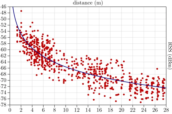
Signal propagation based localization systems use information derived from received signals to localize objects. Information commonly derived from signals is the strength of the signals. The strength of the signal received by a sensor of localization system is called the Received Signal Strength (RSS). Since signal strength decays exponentially over distance, RSS values have a func-tional relation with distance. This funcfunc-tional relation can be used to estimate the distance of a target object to the sensor. Different approaches for target location estimation using RSS are discussed next.
2.2.1 Signal strength based methods
Proximity
In proximity based methods the RSS value is used to define a relative ordering between different sensor nodes. Nodes which receive signals with a higher strength are located closer to the target device compared to nodes which receive lower strength signals. This information is used define a relative ordering of nodes based on proximity to the target. Such systems do not try to make an actual estimate of the distance between the nodes and the target. Instead they rely on the relative ordering to geometrically define an area in the localization space, which contains the location of the target (assuming the ordering is correct). After having identified this area, the centroid of the area is then usually taken as the estimated location of the target.
2.2. SIGNAL BASED LOCALIZATION METHODS 9
Range based methods
Contrary to proximity, range based methods do attempt to estimate the distance between the sensor nodes and the target. This is done using a model that maps the RSS values to distance. The most commonly used model is the Log-Normal Shadowing (LNS) model [16], which will be discussed in section 6.2. A model that defines the relation between RSS and distance generally needs to be calibrated for the environment in which the system operates. The LNS model, for example, includes two parameters which depend on the physical structure and properties of the environment and also on the transmitter strength of the targets. Calibrating the model typically involves measuring the RSS values at a few known distances and then fitting this data on some function that defines the relation between RSS and distance.
When the localization system is operational, the model is used to estimate the distance from each sensor node to the target. Distance estimates are then combined, e.g. via trilateration (see section 2.2.2), to estimate the location of the target. When properly calibrated, range based methods outperform proximity based methods in terms of accuracy [4].
Fingerprinting
Both proximity and range based localization methods assume that an increase in RSS corresponds with a decrease in distance. This is indeed the case if there are no noise factors. In practice, however, the environment is not free of these noise factors. Noise factors may include interference from other transmitters, objects partially blocking the signal (shadowing) and multipath prop-agation. As a result the theoretical relation between RSS and distance is not always accurate. Fingerprinting approaches do not assume that a relation exists between RSS and distance, but instead assume that there is relation between RSS and location. This means that at a certain location the distribution of the RSS values is assumed to remain constant as long as the target does not move and there are no changes in the environment affecting signal propagation.
Using the assumption that RSS distribution depends on location, a fingerprint can be defined for each location in the localization space. This fingerprint describes the characteristics of the signal received by each sensors node for a target at the specified location. Signal characteristics might be the mean RSS value, the median RSS value or a histogram of the RSS values. All fingerprints together form a database. When the localization system is operational, finding the location of a target becomes the problem of selecting a fingerprint from the database that best matches the characteristics of signals received at that time. Usually the location estimate is the (weighted) center of the top 3 or 4 best fingerprint matches. This is called “K-nearest neighbour”, where K is the number of best fingerprint matches which are selected. The reason for selecting fingerprints withK >1 is that the real location of the target generally falls between a few of the fingerprinted locations.
Accuracy of fingerprinting based localization methods depends on the granularity and distribu-tion of the fingerprinted locadistribu-tion. Increasing the number of fingerprints also increases the accuracy. Eventually however, increasing the number of fingerprints does no longer significantly improve lo-calization accuracy [2, 17, 20]. With a sufficiently large fingerprint database, fingerprinting based localization achieves better accuracy compared to proximity and range based localization. This is especially true for environments which contain a lot of noise factors. A major disadvantage of fingerprinting is that it requires a large calibration effort, since each fingerprint is created by measuring the signal characteristics at a specific location.
2.2.2 Time based methods
10 CHAPTER 2. LOCALIZATION BASICS
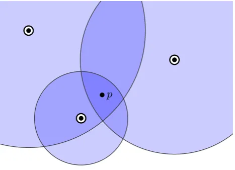
If t0 is the time at which the signal was transmitted and ti is the time at which the signal was received by sensori, then the length of the path is equal to (ti−t0)v, where v is the velocity of the signal propagation. With three of such path length estimates the location of the transmitter can be determined using trilateration, illustrated by figure 2.1.
[image:18.595.182.416.134.303.2]p
Figure 2.1: Estimated target locationp with trilateration.
Localization using TOA requires the clocks of the transmitter and sensors to be synchronized. In addition the transmitter should be able to communicate the time at which the signal was sent (t0) to the localization system. Often however the clock of the transmitter cannot be synchronized or the transmitter cannot send the time of signal emission to the localization system. This is usually the case if one is not able to control the transmitting device because it is a localization target. A solution to this problem is to use Time Difference Of Arrival (TDOA), in which the difference of signal arrival time between pairs of sensors is used. For each pair of sensors the difference of arrival time defines a hyperboloid in the localization space on which the location of the transmitter lies. Three pairs of sensors each produce different hyperboloids, which will ideally intersect in one point: the origin of the signal. Because of noise and errors in the measurements all hyperboloids seldomly intersect at one point. In this case the location estimation becomes an optimization problem. Localization using TDOA is called multilateration. TDOA requires at least 4 sensors where TOA requires only 3 sensors.
Although TDOA does not require the clock of transmitter to be synchronized with the clock of the sensors, it still requires the clocks of the sensors to be synchronized among themselves. Sometimes even this might not be possible for a localization system. This however can be solved using Differential Time Difference Of Arrival (DTDOA). DTDOA works the same as TDOA but eliminates the need for clock synchronization by having a node in the localization system that transmits a signal which is echoed by the localization target. A sensor receives an echo request at timet1 from the transmitter node and echo-response at timet2 from the target. The difference of signal arrival time between two sensorsiandj is then equal to (ti,2−ti,1)−(tj,2−tj,1) +Ti−Tj, whereTiandTj denote the time required for the signal travel from the transmitter node to sensors iandj. These values are assumed to be known, as they can simply be computed from the distance between the transmitter node and the sensors.
2.2.3 Radio interferometric localization
2.3. TECHNOLOGIES 11
between nodes. Because a simple description of how these distances are inferred cannot be given, the interested reader is referred to [23] or [6] for a complete description of radio interferometric localization.
2.2.4 Event rate based methods
Most signals are used to transmit data from one device to another. To enable effective wireless data transfer communication protocols are needed. For example both Bluetooth and Wi-Fi are technologies for wireless data transfer which employ a stack of protocols to enable communication. Typically these protocols include mechanisms to detect errors in the received data due to signal corruption. Some localization systems [22, 18] have effectively used the Bit Error Rate (BER) for localization. The BER appears to increase as the distance between transmitter and receiver increases. Therefore BER has been used as a substitute for RSS, allowing the localization methods discussed in section 2.2.1 (proximity, range based and fingerprinting) to be applied.
Apart from the BER other event rate based measures can be derived from some of the com-munication protocols. For example, the Inquiry Response Rate (IRR) of the Bluetooth device discovery protocol has been used effectively in [3] to estimate the location of Bluetooth enabled devices. In section 8.1 the localization accuracy of IRR compared to other localization methods is reviewed.
2.3
Technologies
Localization systems have been build using a variety of technologies. These technologies can be divided into two classes, those that have been designed for localization and technologies which were designed for another purpose but can be used for localization. Technologies in the first class are called ‘dedicated localization technologies’ and those in the second class are called ‘localization enabling technologies’. In this section an overview of several different technologies from both classes will be given.
2.3.1 Dedicated localization technologies
Radar
Radar is an acronym for ‘RAdio Detection And Ranging’. As the name implies, Radar is a localization system that uses radio waves to determine the location of objects, such as ships, aircrafts and clouds. A Radar installation is able to locate objects by emitting radio pulses, which are reflected by objects on the path of pulses. Reflected pulses are received by the radar installation. The signal power of the received pulses can then be converted to an estimate of the distance between the Radar installation and the object. Radar installations use directed antennas, so the location of an object is determined by its distance from the installation and the current angle of the antenna. Hence a Radar system can localize objects using a single transmitter and receiver only.
Sonar
12 CHAPTER 2. LOCALIZATION BASICS
The direction of objects is determined by using multiple receivers and using the difference of arrival time to find the angle.
GPS
As mentioned in the introduction GPS (Global Positioning System) uses satellites. These satellites continuously send messages, using radio signals, containing the time at which the messages were send and the location of the sending satellite. A GPS receiver uses the time at which the message was received to compute the travelling time of the message from satellite to receiver. The distance between the receiver and satellite can then be computed by multiplying the travel time times the speed of light. Since GPS messages also include the position of the satellite, the location of the GPS receiver can be computed using trilateration. Because GPS receiver clocks are not exactly synchronized with those of the satellites, distance estimates are very rough. To compensate for these estimation errors at least 4 satellites should be in range of the GPS receiver.
Active Bat
The technologies discussed so far were all designed to operate in outdoor environments and are not suitable for indoor localization. However, the Active Bat localization system [15] is meant for accurate indoor localization. The system works by equipping the objects to be localized with a badge that emits ultrasound pulses. Receivers mounted overhead measure the time of flight of the pulses and compute the distance to the target by multiplying the time of flight times the speed of sound. With at least three estimates the system computes the location of the target using trilateration.
2.3.2 Localization enabling technologies
GSM
GSM (Global System for Mobile Communications) is a technology for digital cellular networks, which enables telephony for mobile phones. The technology can, however, also be used to estimate the location of a mobile phone. Base stations surrounding a mobile phone can measure the strength of a roaming signal emitted by the phone. With a propagation model of the radio signals emitted by the phone, the RSS values measured by the base stations surrounding the phone can be used to estimate the distance to the phone. Trilateration can then be used to estimate the location of the device.
Wi-Fi
Wi-Fi is the current standard for small scale fast wireless networks. The name is a trademark for products which use the IEEE 802.11 standards family. Today the technology is usually found in laptops and smart phones. One of the earliest proposals to use Wi-Fi for localization is the RADAR system [2] (not to be confused with Radar technology). Localization using Wi-Fi is possible because Wi-Fi uses radio signals in the 2.4 GHz range and the standard allows software to query the signal strength of devices in range. This enables the use of RSS based localization methods (see section 2.2.1) to estimate the location of target devices.
RFID
2.4. SYSTEM PROPERTIES 13
of response messages from the tags. When such information is available, the RSS based localization methods discussed in section 2.2.1 can be used to estimate the location of an RFID tag.
Bluetooth
In many ways Bluetooth is a technology that is similar to Wi-Fi. It is also a wireless networking technology, but at smaller scale. Bluetooth transmits radio signals at the same frequencies as Wi-Fi does, so many of the localization principles for Wi-Fi are also applicable for Bluetooth. An elaborate discussion of how Bluetooth can used for localization is given in section 4.3.
2.4
System properties
The practical usefulness of a localization system depends on the context in which it will be used. One of key properties that determines whether a localization system is suitable for a particular context is its accuracy. For example, it makes no sense to use GPS for tracking the location of ants. Even if an ant was strong enough to carry a GPS tracking device, the accuracy of the location estimates would be far to low. If one really wishes to track the location of ants, a localization system with sub-decimeter accuracy is required. A Bluetooth localization system is expected to be able to make location estimates somewhere in the range of 1 to 10 meters. Tracking ants is not a viable option using Bluetooth, but tracking people in an office building might be possible.
The list below gives an overview of the other properties which determine to what degree a localization system is suitable for a particular context. These properties are used throughout this thesis as key aspects on which the performance of a localization system will be evaluated.
Accuracy Defined as the average distance between the estimated location and the actual location of an object, i.e. the mean error in location estimates. Note that when this thesis refers to a system with ‘high accuracy’, mean error in location estimates is small compared to a system with ‘low accuracy’. Accuracy is thus inversely proportional to mean estimation error.
Responsiveness The responsiveness determines how quickly the location estimate of a moving target is updated.
Calibration effort Many localization systems need to be calibrated to make location estimates with reasonable accuracy. The amount of effort required for the calibration process can have a big influence on the usefulness of a system, especially if a lot of effort is required. Another factor of the calibration effort is whether it is a process that needs to be performed only once or repetitively. If calibration needs to be performed only once a large effort is less of a problem than if it has to be repeated over time.
Adaptiveness Some changes in the environment may affect the localization system. The ability of the localization system to cope with these changes is called its adaptiveness. A system that is able to adapt to environmental changes can provide better localization accuracy than systems that cannot adapt. An adaptive system can also prevent the need for repeated calibration.
Operational constraints These define under what circumstances the localization system will provide location estimates with reasonable accuracy. For example, some localization sys-tems [15, 10] require a direct line of sight to one or more base stations. Operational con-straints may thus limit the applicability of a localization system.
14 CHAPTER 2. LOCALIZATION BASICS
not exist. In reality most systems make a trade-off between these properties, giving more weight the those properties that are important for the localization context. For example requiring high accuracy usually comes at the cost of increased calibration effort. In section 3.1.1 the minimal requirements for these properties are listed for the context of a localization system used to estimate the location of employees in an office building.
2.5
Current advances
The idea of using Bluetooth technology for localization is not new. Because of its widespread adoption in various mobile devices, Bluetooth has been an attractive technology for unobtrusive localization. This section presents some of the earlier work on Bluetooth based localization systems and discusses how this thesis is related to the earlier work
One of the earliest works on Bluetooth based localization is that of Hallberg and Nilsson [14]. They describe, a localization system based on a calibrated Log-Normal Shadowing (LNS) model. Trilateration is used to estimate target locations, which differs from the approach taken in this thesis in which the location estimate is determined by finding the position in which the difference between expected and measured RSS values is minimized. Another difference is that the RSS values are measured using an active Bluetooth connection. Similar Bluetooth localization systems are described in [8, 9].
Feldman et al. [8], attempt to describe indoor signal propagation using three different models, including the LNS model. The other models relate distance to RSS via quadratic and cubic functions and are given by equations 2.3 and 2.4. With a set of observations the parameters for these two models and the LNS model are determined. One of these models is then selected based on the least squared sum of deviations. Evaluation of this method results in a mean error of 2.06 m, which is similar to results from the current study, as will be presented in section 8.1.
y=c0+c1x+c2x2 (2.3)
y=c0+c1x+c2x2+c3x3 (2.4)
Fernandez et al. [9] recognize that signal propagation may be affected by changes in the en-vironment and thus can invalidate calibration data. They propose a localization system that automatically updates its calibration data using fixed reference devices, similar to the automatic calibration of the LNS model described in section 6.2.1. Other approaches to cope with changes in the environment that affect signal propagation are presented in [13, 30]. Although these works are based on Wi-Fi, the principles also apply for Bluetooth. Haeberlen et al. [13] address the issue by introducing a linear calibration function that maps observed RSS values in the online phase to RSS values as they would have been observed in the training phase. To obtain the parameters for calibration function they use a history of recent observations from which they construct an esti-mate of the calibration parameters. Yin et al. [30] argue that calibration function used in [13] to adapt to environmental changes cannot be uniformly performed across all locations. Instead they present a new algorithm called Location Estimation using Model Trees, that is able to better cope with the non-uniform nature of the environmental changes. This algorithm is based on learning mapping functions in the training phase and dynamically computing the expected signal strength vector spaces in the online phase. The disadvantage of the latter approach is that it still requires manual recalibration, although the amount of effort is significantly reduced.
2.5. CURRENT ADVANCES 15
Machine learning approaches have also been applied for Bluetooth based localization. Mayrhofer et al. [24] use both Neural Network Approximation and Evolutionary Systems Structure Identi-fication techniques to infer the relation between RSS and distance. Of these two techniques, the neural network approximation yields the best results. The authors claim to have achieved a mean localization error of 0.1 m using this technique with 4 base stations. Their data was obtained using a dataset for 7x7 grid with 0.5 m cell sizes. While this approach seems promising, the disadvantage is that it requires a lot of calibration effort. It is also unknown how well this system responds to variances in the uncontrollable localization parameters (see section 5.2).
Another neural network based localization system is presented by Altini et al. [1]. The fun-damental difference between the work of Mayrhofer et al. and the work of Altini et al. is that latter also includes device orientation. This is done by extending the target devices with a compass module. During the calibration phase of the system 4 different neural networks are created, each with a different orientation. In the online phase information provided by the compass module is used to dynamically select one of the 4 networks. Although this approach can provide better loca-tion estimates in the presence of varying orientaloca-tions, having to equip target devices with compass modules is not practical.
The effect of device orientation is addressed by Seshadri et al. [28] by modeling the localiza-tion problem as a stochastic process in which the localocaliza-tion and orientalocaliza-tion of a target device are represented as probability distributions. Estimates of these variables are computed using Bayesian filtering. For each location in the radio map they collect RSSI fingerprints for a number of different orientations. This approach is, however, not practical because of the large amount of calibration effort that is required. The same problem is true for the work of Li et al. [20], which addresses the orientation issue by averaging the RSS values for different directions. For each fingerprint they record the RSS values when facing north, west, south and east. The average of these values for each access point is then used to form a fingerprint.
The main difference between related work and this thesis, is that this study focuses on a prac-tical application of a Bluetooth based localization system. While some of the related contributions provide possible solutions to the problems discussed in section 5.2.4, most of them only focus on a single aspect. The prespective in this thesis is different as it attempts to consider all aspects that might possibly limit a practical application of the localization system.
Summary
This chapter has given an introduction to the localization problem in general. First a formal definition of the localization problem has been given. Also a measure for quantifying localization accuracy has been presented. This measure is the mean error between estimated and real target locations. In addition to accuracy 4 other localization system properties have been described. These are: responsiveness, calibration effort, adaptiveness and operational constraints.
This chapter has also given an overview of the different signal based localization methods that exist. In general the following classes of localization methods can be distinguished: signal strength based, time of arrival based, event rate based and radio interferometric based methods. For some of these classes a short description has been given as to how they work.
Chapter 3
Context
In this chapter the context of the Bluetooth based localization system studied in this thesis is described. This context is important because it governs some of the choices that were made. A use case scenario is applied to define the context. For this use case scenario requirements are set for the localization system properties listed in section 2.4. Also, a set of assumptions for the use case is given. The chapter ends with an overview of the test environment in which empirical measurements were performed to study the performance of Bluetooth localization for different localization methods.
3.1
Use case scenario
The use case scenario for this thesis is a localization system that helps people to find colleagues in an office building. The localization targets are thus people inside the building. To find the location of a specific person in the building, the user logs in on the localization system and then queries the system by either specifying an identifier for that person (the persons name for example) or by manually searching the floor plan of the building on which the locations of all persons are shown. For a person to be localized, that person is required to be carrying a device which is equipped with a Bluetooth module. Also Bluetooth has to be enabled on the device.
3.1.1 Requirements
Based on the use case scenario description several requirements for the localization system can be defined. These requirements are based on the 5 system properties which were defined in section 2.4. As a baseline reference office this thesis considers the building in which the Computer Science department of the University of Twente is situated. This building can be viewed as an example of a typical office building.
• The localization system is able to estimate the location of a person with reasonable accuracy. Reasonable accuracy means here that a person should have no trouble finding another person. Whether the accuracy of the system is reasonable depends on the layout of the building. In a building in with a relatively large line of sight accuracy does not need to be as high as in a building in which the line of sight is more restricted. An accuracy of 5 m is assumed to be sufficient to find someone without problem. Therefore the upper bound on mean localization error should be 5 m.
• A reasonable location estimate should be obtained for a stationary person within at least 5 minutes. Although this upper bound on the responsiveness of the system is rather weak, it is sufficient for most office environments. This is because it is assumed that people in an office building will spend most of their time stationary, e.g. sitting behind a desk or in a conference room. Stationary is considered here as staying within a circle of small radius, because nobody remains completely motionless within a period of 5 minutes. When it is the case that people are moving, the system does not need to estimate with reasonable accuracy. As an extra feature the system might detect that a target is moving so it can warn users of
18 CHAPTER 3. CONTEXT
the system that the location estimate for moving persons might be off by a large amount. This is however not a requirement.
• Calibration effort for the localization system should be minimal. Since calibration effort is usually a function of surface area and office spaces can be quite large, calibration may be a tedious task. Repetition of calibration is therefore especially undesirable. It is hard to place an upper bound on the calibration effort as what is acceptable depends on the particular situation and may include factors such as accessibility and labour costs. For a typical office a maximum initial effort of 5 min per 100 m2 is assumed and no repetitive calibration.
• The system needs to automatically adapt to changes in the environment. This is a direct consequence of the requirement that no repetitive calibration needs to be performed. Changes like objects being added, removed or repositioned affect signal propagation. If the system does not account for these changes, localization accuracy will degrade. Over time changes will accumulate and eventually the localization accuracy may drop below what is reasonable. Therefore the localization system should be able to cope with these changes.
• There should be no other operational constraints than that people to be localized are required to wear a device with a Bluetooth module and that Bluetooth is enabled on the device. If a user does not wear such a device or has Bluetooth disabled, the system will not estimate the location of the person. The reason for selecting this limited set of constraints is that it does not burden the employees in the office. Having to carry a device with Bluetooth is for most people not a burden, because they already do so.
3.1.2 Assumptions
The discussion of localization using Bluetooth in the next chapters makes several assumptions about the environment. These assumptions are listed below. If one of these assumptions is not true it may negatively affect localization accuracy or limit the practical application of the localization system for the target environment. Note that the absence of some assumptions in the list impacts the design of the localization system. For example the list does not include the assumptions that sensors have a line of sight to the target devices or that all target devices are of the same type and model. Some of these absent assumptions are so called uncontrollable parameters of the localization system, which will be discussed in section 5. The assumptions for the context of the desired localization system described in this thesis are:
• People are aware that in order for them to be localized they need to wear a device with Bluetooth capabilities. If they do not wish to be localized they disable Bluetooth on their device.
• People will spend most of their time stationary.
• In all areas of the building in which the localization system operates it is possible to install Bluetooth sensors.
• A homogeneous set of sensors can be installed.
• The location of all sensors is known and the location coordinates are defined in the same reference space.
3.2. TEST ENVIRONMENT 19
• It is sufficient to make location estimates in a two dimensional plane, which is parallel to the floor. This means that estimates are given inxand y coordinates and there is noz(height) component. For most offices this is a reasonable assumption, since floors usually contain a single level. An example of an environment in which this might not be sufficient is a large room which contains balconies.
3.2
Test environment
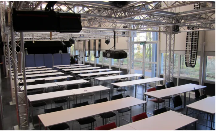
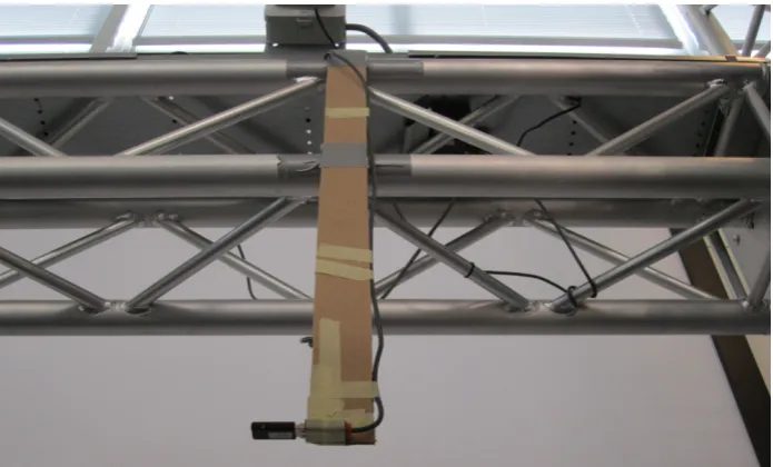
[image:27.595.123.473.328.540.2]Ultimately the localization system will be deployed in an office building. Therefore final tests to see whether a system matches the requirements discussed in section 3.1.1 should be conducted in this type of environment. Such an environment is however not suitable for initial tests, because of its size, complexity and organisational demands. Therefore the tests have been performed in a smaller environment in which most of the parameters which affect localization could be controlled. This environment is the so called ‘SmartXP lab’ and located next to the Computer Science department building of the University of Twente. The ‘SmartXP lab’ is a big room with an approximate dimension of 30 m×10 m×10 m (length, width, height). Originally this room was meant to host various multi-media projects. Currently it is also being used as a presentation and lecture hall. A photo of the ‘SmartXP lab’ is shown in figure 3.1 and a floor plan is shown in figure 3.2.
Figure 3.1: Photo taken from inside of the SmartXP lab on 19 november 2011.
The ‘SmartXP lab’ contains three metal truss installations of which the height can be adjusted. There is also a balcony along the length of the room. In all tests the balcony was ignored and localization was only performed for targets on the ground floor. The room was also filled with various objects like tables, chairs, computers, screens, curtains and even a car. For most tests, however, these objects were moved elsewhere to clear the floor.
3.2.1 Hardware and infrastructure
20 CHAPTER 3. CONTEXT
8 m
left truss middle truss right truss
[image:28.595.244.356.287.462.2]balcony
Figure 3.2: Schematic view of the ‘SmartXP lab’ from above.
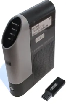
Figure 3.3: Linksys NSLU2 device and Sitecom CN-512 v2 001 Bluetooth dongle
The NLSU2 devices equipped with Bluetooth dongle could serve a dual function. They could act either as sensor or as transmitter. In the latter case the device would become localization target. A device could not serve both functions at the same time. Devices which acted as sensors, which will be called access points from now on, were connected via an ethernet cable to the university network. The access points would send their readings to a central server, via UDP datagram packets. Each packet contained a single tuple consisting of a time stamp, identifier of the access point, MAC address of the target Bluetooth device and the value of reading itself. The central server was configured to act as a relay server, which would redistribute received packets to a set of specified target computers. This allowed for easily performing tests and data analysis from various computers.
Summary
3.2. TEST ENVIRONMENT 21
Because office buildings typically contain a large surface space that need to be covered by the localization system, having to calibrate the system is undesirable. In order to maintain a steady level of localization accuracy, manual recalibration in particular, should be avoided Since changes in environment structure are expected to occur often in minor scale but also on larger scale (though less frequent), the localization system should be able to cope with these changes automatically. People inside an office will spend most of their time stationary, so the minimum requirement for responsiveness is not that strict. The system should be able to give reasonable location estimates for stationary people only and do so within 5 minutes. A reasonable accuracy is obtained when one has no trouble finding another person using the localization system. A minimum mean localization error of 5 m is sufficient for this requirement. For simplicity it is assumed that the localization system is deployed on a single floor only and that 2 dimensional location estimates are sufficient.
Chapter 4
Bluetooth
An introduction to the Bluetooth technology is given in this chapter. First a short history overview is given, followed by a summary of the Bluetooth technology. The chapter concludes with a review of different localization measures that are available for Bluetooth. These measures are reviewed with the localization context in mind and one is selected that best fits the requirements listed in section 3.1.1. Based on this review an answer is formulated to researchquestion 1: ‘Which localization measures are best suitable within the context?’.
4.1
History
Bluetooth was originally a codename for a project lead by a Special Interest Group (SIG) consisting of major companies, like Ericsson, Intel and Nokia. The project was a cooperation between several companies to define a standard for short range wireless communication. When the SIG was about to be launched, the official name for the standard was decided to be PAN, an acronym for Personal Area Networking. However just before the launch, members of the SIG discovered that a trademark search on the internet for PAN resulted in too many hits. This forced the SIG to continue using the name “Bluetooth” at the time of the launch. The intention was to change the name later, once the marketing group had decided on an official name. Bluetooth, however, was picked up quickly by the press and thus eventually became the official name.
The name Bluetooth was suggested by the Swedish company Ericsson, which was a reference to king ‘Harald Bluetooth’. King ‘Harald Bluetooth’ was a Danish king living in the 9-th century and was known for uniting Scandinavia. This latter achievement was the link between the Bluetooth standard, which intended to unite PCs and mobile devices via a short range wireless link [19].
In 1999 the Bluetooth SIG released the first specification of the Bluetooth standard. Since then several new versions of the specification have been published. The most recent version of the specification at time of writing is Bluetooth v4.0. The Bluetooth technology discussed in this thesis report and used in experiments are based on the Bluetooth v1.2 specification. With the exception of Bluetooth HS (High Speed), adopted by the Bluetooth SIG in 2009, all Bluetooth specifications are backwards compatible.
4.2
Technology overview
As mentioned in the previous section, Bluetooth is meant to enable short range wireless communi-cation between devices. It is therefore mainly a replacement for wired communicommuni-cation. Bluetooth uses radio signals in the 2.4 GHz range to transmit data between devices. The 2.4 GHz range is globally license free, which allows the technology to be deployed without additional license costs. Bluetooth is not targeted for a specific application, but supports a multitude of applications. Therefore the technology has been adopted by wide variety of devices, including computers, cell phones, headsets, PDAs and cars.
To support device intercommunication the Bluetooth standard specifies a set of mandatory protocols which must be implemented for each Bluetooth module. In addition a set of optional protocols is also specified. Bluetooth enabled devices are able to query other devices for a list of
24 CHAPTER 4. BLUETOOTH
their supported protocols. On top of these protocols devices can support one or more Bluetooth profiles. These profiles are application specific standards that define an interface to which the devices must conform. Devices can query another device whether it supports a specific profile. This enables a cell phone for example to connect to a wireless headset and use its features via the Headset Profile (HSP). Examples of other frequently used profiles are:
• A2DPAdvanced Audio Distribution Profile. Supports streaming audio between devices. • HFP Hands-Free Profile. Commonly used in cars and hands-free kits to allow people to
make hands free calls with their phone.
• HID Human Interface Device Profile. Provides support for input devices like keyboards, mice and game controllers.
• PANPersonal Area Networking Profile. Allows the encapsulation of network layer 3 packets, which enables devices to connect different networks using a Bluetooth link.
Bluetooth is designed to support low power wireless communication. Therefore one of its features is power control. This feature allows a transmitter to adjust its strength based on the RSSI (see section 4.3) received from another device. With this feature transmission strength can either be increased or decreased to ensure the received signal strength is within an optimal range for the receiver. For some Bluetooth devices this may lead to a significant reduction in consumed power, due to the fact that it does not always need to transmit with maximum power output. Table 4.1 gives an overview of the different power classes which are defined in the Bluetooth standard.
Power class Max power output Min power output Power level control
1 100 mW (20 dBm) 1 mW (0 dBm) mandatory 2 2.5 mW (4 dBm) 0.25 mW (-6 dBm) optional
3 1 mW (0 dBm) - optional
Table 4.1: Bluetooth power classes.
4.3
Localization measures
Bluetooth has several possible measures which can be used as input data for localization algorithms. The first measure discussed is RSSI during inquiry phase, which is the measure used in the rest of the thesis. Section 4.3.2 reviews alternative localization measures for Bluetooth.
4.3.1 Inquiry process based localization
Devices that want to communicate via a Bluetooth link first need to establish a connection. A connection is established via a number of steps and is initiated by a device called the master. When a master device wishes to connect to another device the first step is to discover the devices in range. To do so the master enters an inquiry state in which it continuously sends inquiry messages at pseudo-random frequencies. During this period the master sequentially sends inquiry messages at two different frequencies in a single time slot. In the next time slot the master listens for inquiry response messages at same frequencies from the previous time slot. This process is repeated for a specified period of time, usually 10.24 seconds as recommended by the Bluetooth specification [11], or until the target device has been detected.
4.3. LOCALIZATION MEASURES 25
frequencies, but switches at a much lower rate to ensure that both master and slave eventually use the same frequency. Once a slave device receives an inquiry message, it responds after a small delay with a Frequency Hopping Synchronization (FHS) packet. The FHS packet contains among others a 48-bit MAC address, which is a unique identifier of the slave device.
Using the inquiry process described above a master device can discover and identify the Blue-tooth devices in its range. If it wishes to connect to a certain device, the master waits until it receives a FHS packet with the correct MAC address and then sends an additional message to synchronize both devices and to setup a connection. Upon the receival of an FHS packet, the master device also determines a so called Received Signal Strength Indication (RSSI) value, which depends on the power of the received signal. The Host Command Interface (HCI), an application layer interface to the Bluetooth hardware controller, allows for querying for both the MAC address and RSSI value of the last received FHS packet via an event called ‘Inquiry Result with RSSI’. The Bluetooth specification defines the RSSI value for the ‘Inquiry Result with RSSI’ event as the signal strength in dBm [11]. It is an 8-bit integer in the range from -127 to +20. Measuring the RSSI for a specific target device, identified by its MAC address, from various known locations allows the use of the RSS based localization methods discussed in section 2.2.1 to estimate the location of the target device.
Figure 4.1 shows an example of measured RSS samples in a 1 minute time period for a stationary target and two access points. The dataset from which these RSS samples where taken is described in appendix A. Two observations can be made from this graph. First it displays that for a stationary target, the RSS samples do not form a smooth flat line but instead show a high variation. For example the difference between the maximum and minimum RSS value for the red line is 20 dBm. Secondly it shows that the sample rate is low, about 20 samples per minute. From the complete dataset described in appendix A the average sample rate was 18.6 samples per minute for each access point and device pair.
0 5 10 15 20 25 30 35 40 45 50 55 60 -90
-85 -80 -75 -70 -65 -60 -55
-50 time (sec)
RSS
(dBm)
= access point 1 = access point 2
Figure 4.1: Plot of measured RSS samples for a stationary target and two access points.