Abstract—Existing theories of stiffened composite laminated
plates usually cannot take the bonding imperfections which may exist on the interfaces between the plates and stiffeners into account. This paper developed a three -dimensional semi- analytical model for the free vibration analysis of stiffened composite laminates with interfacial imperfections based on the state space method and the linear spring layer model. This model considered the compatibility of out-of-plane stresses and the discontinuity of displacements on the interfaces between the plate and stiffeners, the transverse shear deformation and the rotary inertia of the plate and stiffeners. Meanwhile, there was no restriction to the thickness of the plate or the height of stiffeners. S everal numerical examples carried out in the present work demonstrated an excellent predictive capability of this model in assessing the natural frequencies and vibration modes. Good agreement had been achieved between the results of this model and the results of the finite element code MS C. Nastran. Besides, the effects of the interfacial stiffness on the lowest four natural frequencies were investigated through the analysis of these numerical results.
Index Terms—Stiffened composite plates, Interfacial
imperfection, Free vibration analysis, Meshless method, Hamilton system, Linear spring-layer
I. INT RODUCT ION
HE stiffened composite laminated plates/shells are widely used as structural components of aircrafts, missiles, and underwater vehicles, etc. Stiffening the plate/shell increases its load carrying capacity and prevents buckling especially in the case of in-plane loading. The primary advantage of stiffened constructions lies in the structural efficiency of the system, because great savings or conservation of weight can be attained with no sacrifice in strength or serviceability. The efficient use of these advanced structures requires a good understanding of their system response characteristics to external causes, such as static response and free vibration.
Dynamic analysis is an important issue for the structural
Manuscript received April 9, 2013; revised December 11, 2013.T his work was supported in part by Aeronautical Science Foundation of China under Grant 20120267002.
Liu Yanhong is with the Aeronautical Engineering College, Civil Aviation University of China, 300300, China. (e-mail: [email protected])
Li Dinghe is with the School of Aerospace, T singhua University, 100084, China. (e-mail: [email protected])
Wang Yanli is with the Aeronautical Engineering College, Civil Aviation University of China, 300300, China. (Corresponding author. phone: +86-18322732310; e-mail: [email protected]).
investigation and design. Determining the free vibration characteristics of a structural system often appears to be the fundamental task. Many researchers have investigated the free vibration of the stiffened composite laminated plates in the past [1-14]. The free vibration analysis for determining their natural frequencies has been performed in a number of ways [1]: 1) equivalent orthotropic plate model [2, 3], 2) composite beam-plate method [4, 5], 3) various matrix methods [6-8], 4) Rayleigh-Ritz method [9], 5) Lagrange multiplier methods [10, 11], 6) modal constraint method [12], 7) the finite difference method [13], and 8) the finite element method [14-16].
Due to the complexity and the large number of the parameters involved, extensive research efforts have been devoted to the free vibration analysis problems over the pas t years by many researchers and from a variety of aspects. Reinforcing the plate/shell with stiffeners complicates the analysis, and several assumptions must be made in order to facilitate a solution especially when the stiffeners are not identical or equally spaced. And the complication would further increase for composite laminated plate/shell structures. Unlike their homogeneous isotropic counterparts, the heterogeneous anisotropic constitution of composite laminated structures often leads to many unique phenomena that can occur on vastly different geometric scales. In early investigations, the classical laminate theory is implemented for the composite laminated plates. However, the laminates made of typical filamentary composite materials, like graphite-epoxy, are susceptible to the thickness effect because their shear modules are significantly smaller than their Young’s modules in the fiber direction. The high ratio of Young’s modulus to shear modulus renders the classical laminate theory inadequate for analysis of composite plates. The first-order shear deformable plate theory (FSDT) [17-20] assumes that the transverse shear deformation should vary linearly along the thickness direction (constant transverse shear strains). Similarly, a laminate is treated as an equivalent single-layer plate when the FSDT is applied to the analysis of laminated plates/shells. In such a way, the shear correction factor must be properly evaluated in order to represent the actual parabolic distribution of transverse shear deformation along the thickness direction in terms of a linear one. By the nature of the FSDT, the traction free condition at the plate surfaces cannot be satisfied. To overcome the drawbacks of the FSDT, the refined shear deformable plate models, including higher order deformable models [21-23], layered (zigzag) models, 3-D elasticity models [24-26] and other methods [27-29], have been developed.
Free Vibration Analysis of Stiffened Composite
Laminated Plates with Interfacial Imperfections
Liu Yanhong, Li Dinghe, Wang Yanli
T
IAENG International Journal of Applied Mathematics, 44:1, IJAM_44_1_04
These theories above are established on the hypothesis that there is no transverse shear deformation or rotator in ertia, so they can neither take all elastic constants into account nor satisfy all fundamental equations. Therefore, the errors will increase as the thickness of plate increases and the stress at interface cannot be exactly calculated. However, by using the state-vector equation method [30-44], the thick plate/shell or laminated plate/shell problems can be treated without any assumptions regarding displacements and stresses. The solution provides the exact continuous field of transverse stresses and displacements across the thickness of laminated structure due to the transfer matrix technique employed. Furthermore, this theory considers the compatibility of out-of-plane stresses and displacements on the interface, the transverse shear deformation, and naturally the rotary inertia of the plate and stiffeners. According to this, Qing and Qiu [45] have developed a novel mathematical model for free vibration analysis of stiffened laminated plates based on the semi-analytical solution of the state space method.
All of the above researches are conducted under a precondition that the stiffeners are assumed to be rigidly connected to the plate, so the bonding imperfection s which may be introduced into the interface between the plate and stiffeners are not taken into account in those theories. But in fact, multifarious interlaminar debondings , like microcrack, inhomogeneity and cavity, are very likely to be introduced into the bond in the process of manufacture or service. During the service lifetime, these tiny flaws can get significant. Therefore, to avoid the local failure of bond or even the whole collapse of structure, the effect of imperfect interfaces on the structural behavior should be accurately evaluated. In recently years, Chen and Cai [46, 47], Chen and Lee [48], Chen and Jung [49] have used analytical methods and numerical methods in Hamilton system to research the problem of interfacial imperfection for composite laminated plates.
This work investigated the problem of free vibration analysis of stiffened composite laminated plates with interfacial imperfections by using spring-layer model, meshfree method and state-vector equation theory. A three-dimensional semi-analytical model was developed and then used to gain the natural frequencies and vibration modes in numerical examples. The main advantage of this semi-analytical model is that the discontinuity of displacements and the compatibility of stresses on the interface between the laminated plate and stiffeners are taken into account. Besides, the present three-dimensional semi-analytical model accounts for the transverse shear deformation and rotary in governing equation s of the structure without any initial assumptions regarding displacement and stress.
II. MAT HEMAT ICAL FORMULAT IONS
A. Meshless Semi-Analytical Model of the Composite
Laminates with Bonding Imperfection
Recently, mesh reduction techniques (meshless or meshfree methods), which are independent of geometric elements, have emerged as effective numerical techniques for solving science and engineering problems. Over the past decade, there have appeared many kinds of meshless methods in the literatures [50-58], such as the element-free Galerkin (EFG) method, the reproducing kernal particle method (RKPM), hp-clouds, the partition of unity method (PUM), the meshless local Petrov-Galerkin (MLPG) method, the smoothed particle hydrodynamics (SPH), the corrected smoothed particle hydrodynamics (CSPH) and the modified smoothed particle hydrodynamics (MSPH). For the Hamilton canonical equation of composite laminates, Li [59-62] has established a class of meshless methods based on the modified Hellinger-Reissner variational principle and radial basis functions.
The shape function of the radial point interpolation method (RPIM) is given in Appendix A. By using RPIM sh ape function, the displacement vector Q and the out-of-plane stress vector Pat any point can be written as follows
e
e ,
P
P N 0
Q
Q 0 N
(1)
where, T
[u v w]
Q , u v w are the total displacement
components along (x, y, z) coordinates, respectively;
T
[
xz yz zz]
P
, σxz, σy z and σzz are the out-of-plane (i.e.transverse) stresses ; Ndiag[ ]Φ3 3 , and Φ is the shape
function of RPIM; e e e T
e[ xz( )z yz( )z zz( )]z
P σ σ σ ;
e e e T
[ ( ) ( ) ( )]
e z z z
Q u v w . The superscript and subscript e
denotes the values of all field nodes. The superscript T signifies matrix transposition.
For the composite laminates with interfacial imperfections, an interfacial spring-layer model, which is similar with the model of an analytical method in references [46-49], is employed to describe the behavior between the upper and lower sub-laminates
, 1 , , 1 , , 1 , , 1 , , 1 , , 1 ,
[ ]
[ ] ,
[ ]
tl bu tl bu
xz xz x
tl bu tl bu
yz yz y
tl bu tl bu
zz zz z
u u R
v v R
w w R
(2)
where, tl, 1
xz
, tl, 1
yz
and tl, 1
zz
denote the out-of-plane
stresses of the top surface of lower sub-laminate; bu,
xz
,
,
bu yz
and bu,zz
denote the out-of-plane stresses of the bottom surface of upper sub-laminate;
, 1
tl
u
,v
tl,1andw
tl,1 denote the displacements of the top surface of lower sub-laminate;u
bu,,v
bu, and bu,w
denote the displacements of the bottom surface of upper sub -laminate;x
R, Ryand Rz
are stiffness parameters in the x, y, and z
directions, respectively. Obviously, Ri 0 (ix y z, , )
IAENG International Journal of Applied Mathematics, 44:1, IJAM_44_1_04
corresponds to a perfect bonding, while Ri (i x y z, , ) implies a completely delaminated case.
Assuming that the spring-layer with n nodes has the same mesh as each layer of sub-laminates, the matrix form of (2) related to node set m1 in undelaminated region and node set m2
in completely delaminated region can be straightly expressed as
, 1 , ,
11 12
, 1 , ,
21 22
,
tl bu bu
e e e
tl bu bu
e e e
P T T P P
T
Q T T Q Q
(3)
where,
1
I 0
N 0 N 0
T
R I
0 N 0 N ,
1
1 1 1
Diag(Rx R Rxn y R Ryn z Rzn)
R ,
0 ( , , , )
1
R i x y z j m
ij
.
Substituting P and Q into the modified H-R variation principle in three dimensional Cartesian coordinate system with (1), and applying the tools of variation and integration, the meshless formulation of the Hamilton canonical equation can be obtained from the first term of modified H-R variation principle, and the boundary term can be obtained from the second term. And then, adding the boundary term to the right side of the meshless formulation of Hamilton canonical equation, the governing equations of each single-layer of the composite laminate can be deduced. Considering the stress equilibrium equations and the displacement compatibility relations at layer interfaces (See (3) for the composite laminates with interfacial imperfections), the meshless semi-analytical model of the composite laminates with bonding imperfection can be obtained by using the transfer matrix technique.
11 12
21 22
( )
(0)
,
( )
(0)
P Q
h
h
Γ
T
T
P
P
Γ
T
T
Q
Q
(4) where, T is the equivalent stiffness matrix. T
[ΓP ΓQ] is known as the equivalent external load vector. P( )h and Q( )h are the stress and displacement vectors relative to the bottom surface. P(0) and Q(0) are the stress and displacement vectors relative to the top surface. In addition, the detailed process of obtaining (4) can be found in Ref. [56-58].
B. Governing Equation of Stiffened Laminated Plate with
Bonding Imperfection
Geometry model and meshfree semi-analytical model of a concentrically stiffened laminated plate with four stiffeners are shown in Fig. 1. In present work, the plate and the stiffeners of a stiffened laminated plate are considered as two three-dimensional laminated structures with bonding imperfection. The semi-analytical three-dimensional models of the plate and the stiffeners are firstly developed by Hamilton canonical equation separately, and then these two models are united together by using the spring-layer model, ensuring the compatibility of stresses and the dis continuity of displacements on the interface between plate and stiffeners (See Fig. 1(b)).
Field nodes in the problem domain are divided into two groups, one group that belongs to the interface between the plate and stiffeners, and the other group that do es not belong to the interface (See Fig. 1(b)). Therefore, the semi-analytical three-dimensional model (5) of the plate can be expressed as (Body force is neglected)
L U
11 12 13 14
p 1 2 p 1
L U
21 22 23 24
p 1 2 p 1
L U
31 32 33 34
s 1 2 s 1
L U
41 42 43 44
s 1 2 s 1
( ) ( )
( ) ( )
,
( ) ( )
( ) ( )
h h h
h h h
h h h
h h h
M M M M
P P
M M M M
Q Q
M M M M
P P
M M M M
Q Q
(5)
where h1 is the thickness of laminated stiffeners; h2 is the
thickness of the laminated plate; subscript s denotes the field nodes that belong to the interface between plate and stiffeners; subscript p denotes the field nodes that do not belong to the interface between plate and stiffeners; s ubscripts L and U
denote the bottom surface and top surface, respectively. In the semi-analytical three-dimensional models of the plate, the behavior equation (3) between the upper and lower sub-laminates can be recast as follows
U L
p p
U L
p p
U L
s s
U L
s s
.
I 0 0 0
P P
R I 0 0
Q Q
0 0 I 0
P P
0 0 R I
Q Q
(6)
Each laminated stiffener is also considered as an l-layered plate, and the assumed field node scheme in every layer is the same as the interface between the plate and stiffeners. For the laminated stiffeners of l layers, the semi-analytical z
x
y
Field nodes
Interfacial imperfections
Background cells
Interface between the stiffeners and plate
h1
h2
Stiffeners
[image:3.596.63.519.54.204.2](a) (b)
Fig. 1. Geometry model and meshfree semi-analytical model of a concentrically stiffened laminated plate with four stiffeners (a) Geometry model; (b) meshfree semi-analytical model.
IAENG International Journal of Applied Mathematics, 44:1, IJAM_44_1_04
three-dimensional model can be expressed as
L U
11 12
s 1 s
L U
21 22
s 1 s
( ) (0)
.
( ) (0)
h h S S P P S S Q Q (7)
Assuming L U
p ( )h1 p (0)
P P , L U
p( )h1 p(0)
Q Q at the field nodes not belonging to the interfaces between plate and stiffeners, the semi-analytical three-dimensional model of the stiffeners can be recast as
L U
p 1 p
L U
p 1 p
L U
11 12
s 1 s
L U
21 22
s 1 s
( ) (0)
( ) (0)
.
( ) (0)
( ) (0)
h h h h
I 0 0 0
P P
0 I 0 0
Q Q
0 0 S S
P P
0 0 S S
Q Q
(8)
In the semi-analytical three-dimensional models of the stiffeners, the behavior equation between the upper and lower sub-laminates can be recast as
U L p p U L p p U L s s U L s s .
I 0 0 0
P P
0 I 0 0
Q Q
0 0 I 0
P P
0 0 R I
Q Q
(9)
Uniting (5), (8) and (9), the overall semi-analytical model of the stiffened laminated plate is
L
11 12 13 14
p 1 2
L
21 22 23 24
p 1 2
L
31 32 33 34
s 1 2
L
41 42 43 44
s 1 2
U p
U p
U
11 12 s
21 22 s
( ) ( ) ( ) ( ) (0) (0) (0) h h h h h h h h
M M M M I 0 0 0
P
M M M M 0 I 0 0
Q
M M M M 0 0 I 0
P
M M M M 0 0 R I
Q
I 0 0 0 P
0 I 0 0 Q
0 0 S S P
0 0 S S QU
. (0) (10) Namely, L U 11 12 1 2 L U 21 22 1 2
( ) (0)
,
( ) (0)
h h h h D D p p D D q q (11) where, L L L T
p s [ , ]
p P P , L L L T
p s
[ , ]
q Q Q , U U U T
p s
[ , ]
p P P ,
U U U T
p s [ , ]
q Q Q .
For natural frequency problem, the top surface and the
bottom surface are stress -free (the stress vector
L U
1 2
(h h) (0)0
p p ). The following equation can be deduced from (11)
U
12 (0)0.
D q
(12) The determinant of the characteristic matrix in (12) must be zero, namely
12( )
0.D
(13) (13) is an implicit polynomial equation which includes the natural frequency. And the natural frequency can be obtained from the characteristic polynomial of (13) by the bisection method.
III. NUMERICAL EXAMPLES
Regarding the interfacial imperfections, we always take 0
z
R to avoid the possibility of material penetration phenomenon which is physically impossible. In this case the continuity of transverse displacement w is ensured between any two adjacent layers contacting with each other, but a shear sliding in the plate plane is allowed. We also assume that the two compliance constants in the plate surface be the same, and
22 22
x y
E E
R .
R h R h
(14) In present work, the numerical computations have been performed by using MATLAB 7.5.0 (R2007b) in DELL PRECISION T3500. The natural frequencies and the vibration modes are obtained for an eccentrically stiffened plate with double stiffeners.
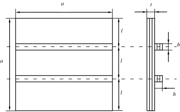
A square angle-ply laminated plate applied with uniform pressure on the bottom surface (See Fig. 2) is employed to illustrate the versatility of the presented method. The laminated plate is eccentrically stiffened by double stiffeners along the y-direction, and the material strong direction is perpendicular to the longitudinal axis of the stiffeners. The boundary case is the complete clamp support (CCCC). The laminated plate and the laminated stiffeners have the same stacking sequence and all the layers of the plate and the stiffeners have the same material properties. And the material properties of each single layer of the laminated plate and the
a a l l l b h t Geometry parameters:
a = 1.2
l = 0.4
t = 0.04
b = 0.04
[image:4.596.70.361.52.234.2]h = 0.02
Fig. 2. An eccentrically stiffened plate with double stiffeners
IAENG International Journal of Applied Mathematics, 44:1, IJAM_44_1_04
stiffeners are as follows:
E1 = 0.9973×10 11
, E2 = 0.5422×10 11
, E3 = 0.5287×10 11
, G12 =
0.26293×10¹¹, G23 = 0.26681×10 11
, G31 = 0.15991×10 11
, v12 =
0.231243, v31 = 0.0321923, v23 = 0.195952.
The schematic diagram of background cells, field nodes and influence domains of this stiffened composite laminated plate with interfacial imperfections are shown in Fig. 3 (483(23×21) field nodes and 81(9×9) square background cells for laminated plate, 63(3×21) field nodes and 18(2×9) rectangular background cells for each stiffener). Critical and complex areas such as the stiffeners are discretized with high density field nodes and small-sized background grids for proper results. The distribution schemes of field nodes, background grids and Gauss points are refined to achieve 1% convergence of the fundamental frequency. For Gauss integral, an 8×8 quadrature scheme (i.e., 64 Gauss points in each background grid) is employed to evaluate domain integrals. The problem domains of the plate and the stiffeners are represented by 1296(36×36) and 108 (3×36) field nodes, 225 (15×15) and 45 (3×15) rectangular background cells respectively in this numerical example.
The accuracy performance of the three-dimensional semi-analytical model is demonstrated through these numerical examples. For the purpose of comparison, a finite element analysis model of this rectangular composite laminated plate stiffened by double stiffeners is developed using the finite element analysis code MSC.Nastran/Patran, as shown in Fig. 4. This three-dimension finite element model can be subdivided into the laminated plate group and the stiffeners group. The results of finite element code MSC.Nastran are obtained by the 8-node Hex Solid64. And the stiffeners are assumed to be rigidly connected to the plate.
Fig. 4. T he finite element analysis model developed in MSC.Patr an for stiffened laminated plate with double stiffeners
The results of the lowest 6 natural frequencies obtained from the present method and from the MSC.Nastran are listed in Table 1. For comparison purpose, the interfacial imperfections between plate and stiffeners are not taken into account (that is
R
R
0
), the stacking sequences of the plate and the stiffeners are [0/0/0] and [0/90/0] respectively, and the plate thickness t = 0.04, the stiffeners thickness h = 0.02. The lowest 3 vibration modes of the present method coincide with those of the MSC.Nastran, as presented in Table 3. It is obvious that the lowest 6 natural frequencies and the lowest 3 vibration modes obtained by present method are in good agreement with the results of MSC.Nastran. In addition, it can be seen from Table 1 and 3 that the thickness of the stiffeners has a significant influence on the natural frequencies and the vibration modes of the structure.Influence of the stiffness of the imperfect interface between the laminated plate and stiffeners on the lowest 4 natural frequencies is listed in Table 2. It can be seen from Table 2 that the natural frequencies decrease with the increasing of value R
0 0.2 0.4 0.6 0.8 1 1.2 0
0.2 0.4 0.6 0.8 1 1.2
Field nodes
Nodes of Background grids
0 0.2 0.4 0.6 0.8 1 1.2 0
0.2 0.4 0.6 0.8 1 1.2
0 0.2 0.4 0.6 0.8 1 1.2 0
0.2 0.4 0.6 0.8 1 1.2
Background grids (Rectangular dashed grids)
[image:5.596.318.539.342.513.2](a) (b)
Fig. 3 Schemes diagram of field nodes and background grids of the laminated plate and the stiffeners. (a) Laminated plate and (b) Stiffeners
IAENG International Journal of Applied Mathematics, 44:1, IJAM_44_1_04
since the total stiffness of the stiffened laminated plate decreases as the value R increases. With the value R
increasing, the greater the thickness ratio of plate and stiffeners is, the more pronounced the decrease of the natural frequencies will be.
IV. CONCLUDING REMARKS
The spring-layer model and the state-vector equation theory have been applied to free vibration analysis of stiffened composite laminated plates with interfacial imperfections based on meshfree method. A three-dimensional semi-analytical model is developed and used to gain the natural frequencies and the vibration modes in numerical
examples. Extensive numerical results are presented for stiffened composite laminated plates with interfacial imperfections, showing an excellent predictive capability of this three-dimensional semi-analytical model. These numerical results also reveal the effects of the thickness of laminated stiffeners and the stiffness of interfacial imperfections on the natural frequencies. The natural frequencies decrease with the decreasing of the interfacial imperfection stiffness, since it reduces the overall stiffness of the stiffened laminated plate. And the greater the thickness ratio of plate and stiffeners is, the more pronouncedly the natural frequencies will decrease when the interfacial imperfection stiffness between the plate
and the stiffeners is increased.
T ABLE1COMP ARISON BETWEEN THE NATURAL FREQUENCIES (HZ) OF PRESENTED METHOD AND THOSE OF MSC.NASTRAN
Stacking sequence h
Mode number
Mode 1 Mode 2 Mode 3 Mode 4 Mode 5 Mode 6
[0/0/0]
0.02
Present 248.7656 482.5879 516.0473 725.9607 840.2212 945.4030
MSC 247.06 474.6 521.88 712.17 835.71 961.34
Error (%) 0.6904 1.6831 -1.1176 1.9364 0.5398 -1.6578 0.04
Present 271.6865 510.2297 565.4324 775.97 929.6519 981.8807
MSC 264.8 521.57 539.98 756.39 948.51 960.59
Error (%) 2.6306 -2.1743 4.7136 2.5886 -1.9882 2.2164
[0/90/0]
0.02
Present 252.7400 493.3325 520.8590 737.3743 859.8646 989.0988
MSC 249.88 485.07 524.34 721.32 853.25 967.48
Error (%) 1.1445 1.7034 -0.6639 2.2257 0.7752 2.2345
0.04
Present 279.5699 516.7317 582.1727 793.7975 930.8429 997.1359
MSC 271.26 526.35 558.18 772.64 960.65 979.23
Error (%) 3.0634 -1.8274 4.2984 2.7383 -3.1328 1.8286
T ABLE2INFLUENCE OF THE STIFFNESS OF INTERFACIAL IMP ERFECTIONS BETWEEN THE LAMINATED PLATE AND STIFFENERS ON THE
LOWEST 4NATURAL FREQUENCIES (HZ)
Stacking sequence h
Mode
number R = 0 R = 0.1 R = 0.2 R = 0.3 R = 0.4 R = 0.5
[0/0/0]
0.02
Mode 1 248.7656 248.5847 248.4155 248.2565 248.1061 247.9656 Mode 2 482.5879 482.1018 481.6631 481.2686 480.9102 480.5811 Mode 3 516.0473 515.5038 514.9965 514.5223 514.0790 513.6623 Mode 4 725.9607 725.2811 724.6497 724.0304 723.4521 722.9009
0.04
Mode 1 271.6865 271.3124 271.0601 270.7795 270.4979 270.2239 Mode 2 510.2297 509.1285 508.1433 507.2345 506.2991 505.2389 Mode 3 565.4324 564.1807 562.9259 561.6267 560.1913 558.3397 Mode 4 775.9706 774.2385 772.6305 771.1207 769.6925 768.3280
0.06
Mode 1 306.0946 305.3240 304.5966 303.9100 303.2465 302.6029 Mode 2 515.8279 514.1575 512.7189 511.4517 510.3197 509.2869 Mode 3 664.2018 661.4015 658.6880 656.0379 653.4273 650.8337 Mode 4 857.0686 853.5778 850.4189 847.5020 844.7703 842.1919
[0/90/0] 0.02
Mode 1 252.7400 252.4764 252.2152 251.9470 251.6235 251.5498 Mode 2 493.3325 492.4999 491.6704 490.8235 489.9456 489.0196 Mode 3 520.8590 519.7417 519.0612 518.4909 517.9774 517.5070 Mode 4 737.3743 736.3535 735.6210 734.5617 733.7050 732.8957
0.04
Mode 1 279.5699 278.6707 277.5483 275.8785 272.4204 270.0456 Mode 2 516.7317 515.5818 514.5581 513.6375 512.9140 512.0398 Mode 3 582.1727 580.1945 578.2228 576.2480 574.2516 572.2489 Mode 4 793.7975 791.5412 789.3953 787.3367 785.3464 765.5850
0.06
Mode 1 319.1994 318.0396 316.5860 304.1609 301.9586 298.2023 Mode 2 525.7963 524.0049 522.4461 521.0640 519.8192 518.6862 Mode 3 687.8515 683.9910 680.1788 676.3583 672.4580 668.3700 Mode 4 871.6583 867.7548 864.0889 860.5820 857.1975 853.8217
IAENG International Journal of Applied Mathematics, 44:1, IJAM_44_1_04
T ABLE3LOWEST 3VIBRATION MODES OF PRESENTED METHOD COINCIDE WITH THAT OF MSC.NASTRAN
h Mode number MSC.Nastran Present
0.02
1
0 0.2
0.4 0.6
0.8 1
1.2 0 0.2
0.4 0.6
0.8 1 -0.02
0 0.02 0.04
2
0 0.2 0.4 0.6 0.8 1 1.2
0 0.2 0.4 0.6 0.8 1 1.2 -0.02
0 0.02 0.04
3
0 0.2 0.4 0.6 0.8 1
1.2 0
0.2 0.4 0.6 0.8 1 -0.02
0 0.02 0.04
0.04
1
0 0.2
0.4 0.6
0.8 1
1.2 0 0.2
0.4 0.6
0.8 1
1.2 -0.02
-0.01 0 0.01
2
0 0.2
0.4 0.6
0.8 1
1.2 0 0.2
0.4 0.6
0.8 1
1.2 -0.02
0 0.02 0.04
3
0 0.2
0.4 0.6
0.8 1
1.2 0 0.2
0.4 0.6
0.8 1
1.2 -0.02
0 0.02 0.04
IAENG International Journal of Applied Mathematics, 44:1, IJAM_44_1_04
APPENDIX A
Consider a continuous function u(x) defined on a 2D domain Ω with a set of suitably located nodes in it. An interpolation of u(x) in the neighborhood of a point XQ using RBFs and polynomial basis is written as
( ) ( ) ( ) ( ) ( )
Q Q
1 1
T( ) T( ) ,
n m
u a p b
i j i
i j
x R x x x x
i
R x a p x b
(A.1)
with the constraint
T 1
( ) ( ) , 1, 2, , ,
m
j i m
j
j m
p x b p x a 0(A.2) and the vectors a, b, T
( )
R x and T
( )
p x in (A.1) are defined as
T 1 2
[a a an] ,
a
(A.3a)
T 1 2
[b b bm] ,
b (A.3b)
T
1 2 3
( )[ ( ), ( ), ( ), , n( )],
R x R x R x R x R x
(A.3c)
T
1 2 3
( )[ ( ), ( ), ( ), , m( )].
p x p x p x p x p x (A.3d)
Here, Ri( )x is a radial basis function associated with node i
(i.e., for the modified multiquadrics (MQ) used in this present
work, 2 2
( ) [ ( ) ]q
i c c
R x r d , where c and q are shape parameters, and dc is a characteristic length that relates to the nodal spacing in the local support domain of the point of interest x, and it is usually the average nodal spacing for all the nodes in the local support domain); n is the number of nodes in the neighborhood of XQ,pj( )x is a monomial in the space coordinates T
[ , ]x y
x ; m is the number of monomial basis functions (usually m<n); ai(xQ)andbj(xQ), which vary with
the point XQ, are coefficients of Ri( )x andpj( )x , respectively.
When utilizing radial basis functions , several shape parameters need to be determined for good performance. In general, these parameters can be determined by numerical examinations for given types of problems . For example, Wang and Liu left the parameter q open to any real variable, and found that q = 0.98 or 1.03 led to good results in the analysis of two-dimensional solid and fluid mechanics problems in the Lagrangian system [61, 62]. In the present work, the optimum values of the shape parameters are obtained by repetitious numerical experimentation for the present three-dimensional model. Here the optimum values of shape parameters for the MQ are determined as c= 0.03 and q = 1.03.
Requiring that the function u(x) given by (A.1) equals its value at n nodes in the vicinity of the point XQ, we get the
following set of simultaneous linear algebraic equations for the coefficients ai(xQ)andbj(xQ)
UsR a0 P bm , (A.4)
where, T
1 2
[ ]
s u u un
U , rk (xkxi)2(xkxi) ,2
1 1 2 1 1 1 2 2 2 2 0 1 2 ( ) ( ) ( ) ( ) ( ) ( ) ( ) ( ) ( ) n n
n n n n
R r R r R r
R r R r R r
R r R r R r
R ,
1 1 1 2 2 2
1 ( )
1 ( )
1 ( )
m m m
n n m n
x y p
x y p
x y p
x x P x .
(A.4) and (A.2) can be expressed in matrix form as
0 0 T . m s s m R P U a U Ga P 0 0 b (A.5) The solution of (A.5) is
1 0 s,
a G u (A.6)
where, 0T m
m R P G
P 0 . And conditions (A.2) ensure that the
matrix G is non-singular and hence invertible. Thus (A.1) becomes
T T
1 T1
( ) ( ) ( ) ( ) ,
n
s s i i
i
u
u
x R x p x G U Φ x U
(A.7) where
T T T 1
1 2 1
( ) ( ) ( )
( ), ( ), , n( ), n ( ), , n m( ) .
Φ x R x p x G
x x x x x
(A.8) The derivatives ofn( )x can be obtained as follows
( ) ( ) ( ) ( ( )) . ( )
R x R x p x
GΦ x
p x
x x x x
(A.9)
REFERENCES
[1] J. W. Nicholson, “ Free vibration of stiffened rectangular plates using Green's functions and integral equations,” AIAA Journal, vol. 24, pp. 485-491, 1986.
[2] W. H. Hoppmann and L.S.Magness, “ Nodal patterns of the free flexural vibration of stiffened plates,” ASME Journal of Applied Mechanics, vol. 24, pp. 526-530, 1957.
[3] T . Wah, “ Vibration of stiffened plates,” The Aeronautical Quarterly, vol. 15, pp.285-298, 1964.
[4] C. S. Smith, Bending, buckling and vibration of orthotropic plate-beam structures,” Journal of Ship Research, vol. 12, pp. 249-268, 1968.
[5] B. R. Long, “ Vibration of eccentrically stiffened plates,” Shock and Vibration Bulletin, vol. 38, pp. 45-53, 1968.
[6] C. A. Mercer, C. Seavey, “ Prediction of natural frequencies and normal modes of skin-stringer panel rows,” Journal of Sound and Vibration, vol. 6, pp. 149-162, 1967.
[7] B. R. Long, “ A stiffness-type analysis of the vibration of a class of stiffened plates,” Journal of Sound and Vibration, vol. 16, pp. 323-335, 1971.
[8] S. Shimizu, “ Free vibration analysis of stiffened plates,” in Second U.S.-Japan Sem inar, Advances in Com puting Methods in Structural Mechanics and Design Conference, T he University of Alabama Press, Huntsville, AL, 1972, pp. 219 -236.
[9] C. L. Kirk, “ Natural frequencies of stiffened rectangular plates,”
Journal of Sound and Vibration, vol. 13, pp.375-388, 1970. [10] E. H. Dowell, “ Free vibrations of an arbitrary structure in terms of
component modes,” ASME Journal of Applied Mechanics, vol. 39, pp. 727-732, 1972.
[11] G. Rosenhouse, E. Goldfracht , “ Use of Lagrange multipliers with polynomial series for dynamic analysis of constrained plates, Part II: Lagrange multipliers,” Journal of Sound and Vibration, vol. 92, pp. 95-106, 1984.
IAENG International Journal of Applied Mathematics, 44:1, IJAM_44_1_04
[12] J. G. M. HKerstens, “ Vibration of complex structures: T he modal constraint method,” Journal of Sound and Vibration, vol. 76, pp.467-480, 1981.
[13] G. Aksu, “ Free vibration analysis of stiffened plates by including the effect of inplane inertia,” ASME Journal of Applied Mechanics, vol. 49, pp. 206-212, 1982.
[14] P. S. Nair, M. S. Rao, “ On vibration of plates with varying stiffener length,” Journal of Sound and Vibration, vol. 95, pp. 19-29, 1984.
[15] Avadesh K. Sharma, N. D. Mittal, “ Free vibration analysis of laminated composite plates with elastically restrained edges using FEM,” Central European Journal of Engineering, vol. 3, no. 2, pp. 306-315, 2013.
[16] Kuo Mo Hsiao, Wen Yi Lin, and Fumio Fujii, “ Free Vibration Analysis of Rotating Euler Beam by Finite Element Method,”
Engineering Letters, vol. 20, no. 3, pp. 253-258, 2012. [17] J. M. Whitney, “ T he effect of transverse shear deformation in
the bending of laminated plates,” Journal of Com posite Materials, vol. 3, pp. 534-547, 1969.
[18] J. M. Whitney, N. J. Pagano, “ Shear deformation in heterogeneous anisotropic plates,” Journal of Applied Mechanics, vol. 37, pp. 1031-6, 1970.
[19] E. Reissner, “ Note on the effect of transverse shear deformation in laminated anisotropic plates,” Com puter Methods in Applied Mechanics and Engineering, vol. 20, pp. 203-9, 1979. [20] J. N. Reddy, Energy principle and variational m ethods in applied
m echanics, 2nd Edition. New York: John Wiley, 2002. [21] J. M. Whitney, C. T . Sun, “ A high order theory for extensional
motion of laminated composites,” Journal of Sound and Vibration, vol. 30, pp. 85-97, 1973.
[22] J. N. Reddy, “ A simple high-order theory for laminated composite plates,” Journal of Applied Mechanics, vol. 51, pp. 745-752, 1984.
[23] F.A. Fazzolari, M. Boscolo, J.R. Banerjee, “ An exact dynamic stiffness element using a higher order shear deformation theory for free vibration analysis of composite plate assemblies,”
Com posite Structures, vol. 96, pp. 262–278, 2013.
[24] J. N. Reddy, “ An evaluation of equivalent -single-layer and layerwise theories of composite laminates,” Com posite Structures, vol. 25, pp. 21-35, 1993.
[25] D. H. Robbins, J. N. Reddy, “ Modeling of thick composites using a layer-wise laminated theory,” International Journal Num erical Methods in Engineering, vol. 36, pp. 655-677, 1993.
[26] C.M.C. Roquea, J.D. Rodriguesa, A.J.M. Ferreirab, “ Static Deformations and Vibration Analysis of Composite and Sandwich Plates Using a Layerwise T heory and a Local Radial Basis Functions-Finite Differences Discretization,” Mechanics of Advanced Materials and Structures, vol. 20, no. 8, pp. 666-678, 2013.
[27] R. L. Spilker, “ Hybrid-stress eight -node element for thin and thick multilayer laminated plates,” International Journal Num erical Methods in Engineering, vol. 18, pp. 801-828, 1982. [28] A. K. Noor, W. S. Burton, “ Assessment of computational models for of multi-layered composite shells,” Applied Mechanics Reviews, vol. 43, pp. 67-97, 1990.
[29] F. Auricchio, F. Sacco, “ A mixed-enhanced finite-element for the
analysis of laminated composite plates,” International Journal Num erical Methods in Engineering, vol. 44, pp. 1481-1504, 1999.
[30] Y.B. Leon, “ A state space approach to elasticity,” Journal of the Franklin Institute, vol. 299, pp. 33-41, 1975.
[31] D.Chan, U.Santhosh. Natural frequencies of cross-ply laminates by state space approach,” Journal of Sound and Vibration, vol. 136, pp. 413-424, 1990.
[32] J.R.Fan, J.Q.Ye, “ Exact solutions for axisymmetric vibration of laminated circular plate,” Journal of Engineering Mechanics ASCE, vol. 116, pp. 920-7, 1990.
[33] R.Steele, Y.Y.Kim, “ Modified mixed variational principle and the state-vector equation for elastic bodies and shells of revolution ,”
Journal of Applied Mechanics, vol. 59, pp. 587-595, 1992. [34] G.H.Qing, J.J.Qiu, Y.H.Liu, “ A semi-analytical solution for
dynamic analysis of plate with piezoelectric patches,”
International Journal of Solids and Structures, vol. 43, pp. 1388-1403, 2006.
[35] G.H.Qing, Y.H.Liu, J.J.Qiu, X.J.Meng, “ A semi-analytical method for the free vibration analysis of thick double-shell systems,”
Finite Elem ents in Analysis and Design, vol. 42, pp. 837-845, 2006.
[36] L.M.T ang, G.P.Zhou, “ Mixed formulation and Hamilton canonical equations of theory of elasticity ,” Com putational Structural Mechanics and Applications, vol. 8, pp. 343-9, 1991 (in Chinese).
[37] H.J.Ding, W.Q.Chen, R.Q.Xu, “ New state space formulations for transversely isotropic piezoelectricity with application ,”
Mechanics research com m unications, vol. 27, pp. 319-326, 2000.
[38] W.X.Zhong, A new system atic m ethodology for theory of elasticity (in Chinese). Dalian: Dalian University of T echnology Press, 1995.
[39] W.X.Zhong, Sym plectic system of applied m echanics (in Chinese). Beijing: Science Press, 2003.
[40] P.R.Heyliger, P.Brooks, “ Free vibration of piezoelectric laminates in cylindrical bending,” International Journal of Solids and Structures, vol. 32, pp. 2945-2959, 1995.
[41] G.P.Zou, L.M.T ang, “ A semi-analytical solution for thermal stress analysis of laminated composite plates in the Hamiltonian system,” Com puter & Structures, vol. 55, pp. 113-118, 1995. [42] H.Y.Sheng, J.Q.Ye, “ A three-dimensional state space finite
element solution for laminated composite cylindrical shells,”
Com puter Methods in Applied Mechanics and Engineering, vol. 192, pp. 2441-2459, 2003.
[43] S.S.Vel, R.C.Mewer, R.C.Batra, “ Analytical solution for the cylindrical bending vibration of piezoelectric composite plates,”
International Journal of Solids and Structures, vol. 4, pp. 1625-1643, 2004.
[44] Z.Q.Cheng, R.C.Batra, “ T hree-dimensional asymptotic analysis of multiple-electroded piezoelectric laminates,” Am erican Institute of Aeronautics and Astronautics Journal, vol. 38, pp. 317-325, 2000.
[45] G.H.Qing, J.J.Qiu, Y.H.Liu, “ Free vibration analysis of stiffened laminated plates,” International Journal of Solids and Structures, vol. 43, pp. 1357-1371, 2006.
[46] W.Q. Chen, J.B.Cai, G.R.Ye, “ Exact solution of cross-ply laminates with bonding interfacial imperfections,” AIAA Journal, vol. 41, pp. 2244-2250, 2003.
[47] W.Q.Chen, J.B.Cai, G.R.Ye, Y.F.Wang, “Exact
three-dimensional solutions of laminated orthotropic
piezoelectric rectangular plates featuring interlaminar bonding imperfections modeled by a general spring layer,” International Journal of Solids and Structures, vol. 41, pp. 5247-5263, 2004. [48] W.Q.Chen, K.Y.Lee, “ Exact solution of angle-ply piezoelectric laminates in cylindrical bending with interfacial imperfections,”
IAENG International Journal of Applied Mathematics, 44:1, IJAM_44_1_04
Com posite Structures, vol. 65, pp. 239-337, 2004.
[49] W.Q.Chen, J.P.Jung, K.Y.Lee, “ Static and dynamic behavior of simply-supported cross-ply laminated piezoelectric cylindrical panels with imperfect bonding,” Com posite Structures, vol. 74, pp. 265-276, 2006.
[50] T .Belytschko, Y.Y.Lu, L.Gu, “ Element -free Galerkin methods,”
International Journal for Num erical Methods in Engineering, vol. 37, pp. 229-256, 1994.
[51] W.K.Liu, S.Jun, Y.Zhang, “ Reproducing kernel particle methods,” International Journal for Num erical Methods Fluids, vol. 20, pp. 1081-1106, 1995.
[52] C.A.Duarte, J.T .Oden, “ H-p adaptive method using clouds,”
Com puter Methods in Applied Mechanics and Engineering, vol. 139, pp. 237-262, 1996.
[53] I.Babuska, J.Melenk, “ Partition of unity method,” International Journal for Num erical Methods in Engineering, vol. 40, pp. 727-758, 1997.
[54] S.N.Atluri, T .Zhu, “ New Meshless Local Petrov-Galerkin (MLPG) approach in computational mechanics,” Com putational Mechanics, vol. 22, pp. 117-127, 1998.
[55] S.N. Atluri, S.Shen, The Meshless Local Petrov-Galerkin (MLPG) Method. T ech Science Press, 2002.
[56] R.A.Gingold, J.J.Monaghan, “ SAoothed particle hydrodynamics: theory and application to nonspherical stars,” Mon. Not. Roy
Astron. Soc., vol. 181, pp. 375-389, 1977.
[57] J.K.Chen, J.E.Beraun, T .C.Carney, “ A corrective smoothed particle method for boundary value problems in heat conduction ,”
International Journal for Num erical Methods in Engineering, vol. 46, pp. 231-252, 1999.
[58] G.M.Zhang, R.C.Batra, “Modified SAoothed particle hydrodynamics method and its application to transient problems,” Com putational Mechanics, vol. 34, pp. 137-146, 2004.
[59] D.H.Li, D.Chen, J.X.Xu, “ Meshless Method with Radial Basis Functions for Hamilton Canonical Equation,” Advanced Materials Research, vol. 194-196, pp. 1407-1416, 2011. [60] D.H.Li, J.X.Xu, G.H. Qing, Sensitivity analysis of composite
laminated plates with bonding imperfection in Hamilton system ,”
Applied Mathem atics and Mechanics, vol. 31, pp. 1549-1560, 2010.
[61] D.H.Li, G.H.Qing, Y.H.Liu, “A three-dimensional
semi-analytical model for the composite laminated plates with a stepped lap repair,” Com posite Structures, vol. 93, pp. 1673-1682, 2011.
[62] D.H.Li, J.X.Xu, G.H.Qing, “ Free vibration analysis and eigenvalues sensitivity analysis for the composite laminates with interfacial imperfection,” Com posite, Part: B, vol. 42, pp. 1588-1595, 2011.