NONRESIDENT
TRAINING
COURSE
SEPTEMBER 1998
Navy Electricity and
Electronics Training Series
Module 23—Magnetic Recording
DISTRIBUTION STATEMENT A: Approved for public release; distribution is unlimited. Although the words “he,” “him,” and
PREFACE
By enrolling in this self-study course, you have demonstrated a desire to improve yourself and the Navy. Remember, however, this self-study course is only one part of the total Navy training program. Practical experience, schools, selected reading, and your desire to succeed are also necessary to successfully round out a fully meaningful training program.
COURSE OVERVIEW: To introduce the student to the subject of Magnetic Recording who needs such
a background in accomplishing daily work and/or in preparing for further study.
THE COURSE: This self-study course is organized into subject matter areas, each containing learning
objectives to help you determine what you should learn along with text and illustrations to help you understand the information. The subject matter reflects day-to-day requirements and experiences of personnel in the rating or skill area. It also reflects guidance provided by Enlisted Community Managers (ECMs) and other senior personnel, technical references, instructions, etc., and either the occupational or naval standards, which are listed in the Manual of Navy Enlisted Manpower Personnel Classifications
and Occupational Standards, NAVPERS 18068.
THE QUESTIONS: The questions that appear in this course are designed to help you understand the
material in the text.
VALUE: In completing this course, you will improve your military and professional knowledge.
Importantly, it can also help you study for the Navy-wide advancement in rate examination. If you are studying and discover a reference in the text to another publication for further information, look it up.
1998 Edition Prepared by CTMC(SS) Milton Charles Georgo
Published by
NAVAL EDUCATION AND TRAINING PROFESSIONAL DEVELOPMENT
AND TECHNOLOGY CENTER
Sailor’s Creed
“I am a United States Sailor.
I will support and defend the
Constitution of the United States of
America and I will obey the orders
of those appointed over me.
I represent the fighting spirit of the
Navy and those who have gone
before me to defend freedom and
democracy around the world.
I proudly serve my country’s Navy
combat team with honor, courage
and commitment.
TABLE OF CONTENTS
CHAPTER PAGE
1. Introduction to Magnetic Recording... 1-1
2. Magnetic Tape ... 2-1
3. Magnetic Tape Recorder Heads ... 3-1
4. Magnetic Tape Recorder Transports ... 4-1
5. Magnetic Tape Recorder Record and Reproduce Electronics ... 5-1
6. Magnetic Tape Recorder Specifications... 6-1
7. Digital Magnetic Tape Recording ... 7-1
8. Magnetic Disk Recording... 8-1
APPENDIX
I. Glossary... AI-1
II. References ... AII-1
CREDITS
The figures listed below and included in this edition of NEETS, Module 23, Magnetic Recording, were provided by Datatape, Inc. Permission to use these illustrations is gratefully acknowledged.
SOURCE FIGURE
NAVY ELECTRICITY AND ELECTRONICS TRAINING
SERIES
The Navy Electricity and Electronics Training Series (NEETS) was developed for use by personnel in many electrical- and electronic-related Navy ratings. Written by, and with the advice of, senior technicians in these ratings, this series provides beginners with fundamental electrical and electronic concepts through self-study. The presentation of this series is not oriented to any specific rating structure, but is divided into modules containing related information organized into traditional paths of instruction.
The series is designed to give small amounts of information that can be easily digested before advancing further into the more complex material. For a student just becoming acquainted with electricity or electronics, it is highly recommended that the modules be studied in their suggested sequence. While there is a listing of NEETS by module title, the following brief descriptions give a quick overview of how the individual modules flow together.
Module 1, Introduction to Matter, Energy, and Direct Current, introduces the course with a short history
of electricity and electronics and proceeds into the characteristics of matter, energy, and direct current (dc). It also describes some of the general safety precautions and first-aid procedures that should be common knowledge for a person working in the field of electricity. Related safety hints are located throughout the rest of the series, as well.
Module 2, Introduction to Alternating Current and Transformers, is an introduction to alternating current
(ac) and transformers, including basic ac theory and fundamentals of electromagnetism, inductance, capacitance, impedance, and transformers.
Module 3, Introduction to Circuit Protection, Control, and Measurement, encompasses circuit breakers,
fuses, and current limiters used in circuit protection, as well as the theory and use of meters as electrical measuring devices.
Module 4, Introduction to Electrical Conductors, Wiring Techniques, and Schematic Reading, presents
conductor usage, insulation used as wire covering, splicing, termination of wiring, soldering, and reading electrical wiring diagrams.
Module 5, Introduction to Generators and Motors, is an introduction to generators and motors, and
covers the uses of ac and dc generators and motors in the conversion of electrical and mechanical energies.
Module 6, Introduction to Electronic Emission, Tubes, and Power Supplies, ties the first five modules
together in an introduction to vacuum tubes and vacuum-tube power supplies.
Module 7, Introduction to Solid-State Devices and Power Supplies, is similar to module 6, but it is in
reference to solid-state devices.
Module 8, Introduction to Amplifiers, covers amplifiers.
Module 9, Introduction to Wave-Generation and Wave-Shaping Circuits, discusses wave generation and
wave-shaping circuits.
Module 10, Introduction to Wave Propagation, Transmission Lines, and Antennas, presents the
Module 11, Microwave Principles, explains microwave oscillators, amplifiers, and waveguides.
Module 12, Modulation Principles, discusses the principles of modulation.
Module 13, Introduction to Number Systems and Logic Circuits, presents the fundamental concepts of
number systems, Boolean algebra, and logic circuits, all of which pertain to digital computers.
Module 14, Introduction to Microelectronics, covers microelectronics technology and miniature and
microminiature circuit repair.
Module 15, Principles of Synchros, Servos, and Gyros, provides the basic principles, operations,
functions, and applications of synchro, servo, and gyro mechanisms.
Module 16, Introduction to Test Equipment, is an introduction to some of the more commonly used test
equipments and their applications.
Module 17, Radio-Frequency Communications Principles, presents the fundamentals of a
radio-frequency communications system.
Module 18, Radar Principles, covers the fundamentals of a radar system.
Module 19, The Technician's Handbook, is a handy reference of commonly used general information,
such as electrical and electronic formulas, color coding, and naval supply system data.
Module 20, Master Glossary, is the glossary of terms for the series.
Module 21, Test Methods and Practices, describes basic test methods and practices.
Module 22, Introduction to Digital Computers, is an introduction to digital computers.
Module 23, Magnetic Recording, is an introduction to the use and maintenance of magnetic recorders and
the concepts of recording on magnetic tape and disks.
Module 24, Introduction to Fiber Optics, is an introduction to fiber optics.
Embedded questions are inserted throughout each module, except for modules 19 and 20, which are reference books. If you have any difficulty in answering any of the questions, restudy the applicable section.
Although an attempt has been made to use simple language, various technical words and phrases have necessarily been included. Specific terms are defined in Module 20, Master Glossary.
Considerable emphasis has been placed on illustrations to provide a maximum amount of information. In some instances, a knowledge of basic algebra may be required.
Assignments are provided for each module, with the exceptions of Module 19, The Technician's
Handbook; and Module 20, Master Glossary. Course descriptions and ordering information are in
Throughout the text of this course and while using technical manuals associated with the equipment you will be working on, you will find the below notations at the end of some paragraphs. The notations are used to emphasize that safety hazards exist and care must be taken or observed.
WARNING
AN OPERATING PROCEDURE, PRACTICE, OR CONDITION, ETC., WHICH MAY RESULT IN INJURY OR DEATH IF NOT CAREFULLY OBSERVED OR FOLLOWED.
CAUTION
AN OPERATING PROCEDURE, PRACTICE, OR CONDITION, ETC., WHICH MAY RESULT IN DAMAGE TO EQUIPMENT IF NOT CAREFULLY OBSERVED OR FOLLOWED.
NOTE
INSTRUCTIONS FOR TAKING THE COURSE
ASSIGNMENTS
The text pages that you are to study are listed at the beginning of each assignment. Study these pages carefully before attempting to answer the questions. Pay close attention to tables and illustrations and read the learning objectives. The learning objectives state what you should be able to do after studying the material. Answering the questions correctly helps you accomplish the objectives.
SELECTING YOUR ANSWERS
Read each question carefully, then select the BEST answer. You may refer freely to the text. The answers must be the result of your own work and decisions. You are prohibited from referring to or copying the answers of others and from giving answers to anyone else taking the course.
SUBMITTING YOUR ASSIGNMENTS
To have your assignments graded, you must be enrolled in the course with the Nonresident Training Course Administration Branch at the Naval Education and Training Professional
Development and Technology Center
(NETPDTC). Following enrollment, there are two ways of having your assignments graded: (1) use the Internet to submit your assignments as you complete them, or (2) send all the assignments at one time by mail to NETPDTC.
Grading on the Internet: Advantages to
Internet grading are:
• you may submit your answers as soon as you complete an assignment, and
• you get your results faster; usually by the next working day (approximately 24 hours).
In addition to receiving grade results for each assignment, you will receive course completion confirmation once you have completed all the
assignments. To submit your assignment answers via the Internet, go to:
http://courses.cnet.navy.mil
Grading by Mail: When you submit answer
sheets by mail, send all of your assignments at one time. Do NOT submit individual answer sheets for grading. Mail all of your assignments in an envelope, which you either provide yourself or obtain from your nearest Educational Services Officer (ESO). Submit answer sheets to:
COMMANDING OFFICER NETPDTC N331
6490 SAUFLEY FIELD ROAD PENSACOLA FL 32559-5000
Answer Sheets: All courses include one
“scannable” answer sheet for each assignment. These answer sheets are preprinted with your SSN, name, assignment number, and course number. Explanations for completing the answer sheets are on the answer sheet.
Do not use answer sheet reproductions: Use
only the original answer sheets that we provide—reproductions will not work with our scanning equipment and cannot be processed.
Follow the instructions for marking your answers on the answer sheet. Be sure that blocks 1, 2, and 3 are filled in correctly. This information is necessary for your course to be properly processed and for you to receive credit for your work.
COMPLETION TIME
PASS/FAIL ASSIGNMENT PROCEDURES
If your overall course score is 3.2 or higher, you will pass the course and will not be required to resubmit assignments. Once your assignments have been graded you will receive course completion confirmation.
If you receive less than a 3.2 on any assignment and your overall course score is below 3.2, you will be given the opportunity to resubmit failed assignments. You may resubmit failed assignments only once. Internet students will
receive notification when they have failed an assignment--they may then resubmit failed assignments on the web site. Internet students may view and print results for failed assignments from the web site. Students who submit by mail will receive a failing result letter and a new answer sheet for resubmission of each failed assignment.
COMPLETION CONFIRMATION
After successfully completing this course, you will receive a letter of completion.
ERRATA
Errata are used to correct minor errors or delete obsolete information in a course. Errata may also be used to provide instructions to the student. If a course has an errata, it will be included as the first page(s) after the front cover. Errata for all courses can be accessed and viewed/downloaded at:
http://www.advancement.cnet.navy.mil
STUDENT FEEDBACK QUESTIONS
We value your suggestions, questions, and criticisms on our courses. If you would like to communicate with us regarding this course, we encourage you, if possible, to use e-mail. If you write or fax, please use a copy of the Student Comment form that follows this page.
For subject matter questions:
E-mail: [email protected] Phone: Comm: (850) 452-1001, ext. 1728
DSN: 922-1001, ext. 1728 FAX: (850) 452-1370 (Do not fax answer sheets.)
Address: COMMANDING OFFICER
NETPDTC N315
6490 SAUFLEY FIELD ROAD PENSACOLA FL 32509-5237
For enrollment, shipping, grading, or
completion letter questions
E-mail: [email protected] Phone: Toll Free: 877-264-8583
Comm: (850) 452-1511/1181/1859 DSN: 922-1511/1181/1859
FAX: (850) 452-1370 (Do not fax answer sheets.)
Address: COMMANDING OFFICER
NETPDTC N331
6490 SAUFLEY FIELD ROAD PENSACOLA FL 32559-5000
NAVAL RESERVE RETIREMENT CREDIT
If you are a member of the Naval Reserve, you will receive retirement points if you are authorized to receive them under current directives governing retirement of Naval Reserve personnel. For Naval Reserve retirement, this course is evaluated at 2 points. (Refer to Administrative Procedures for Naval
Reservists on Inactive Duty, BUPERSINST
Student Comments
Course Title:
NEETS Module 23
Magnetic Recording
NAVEDTRA:
14195
Date:
We need some information about you:
Rate/Rank and Name: SSN: Command/Unit
Street Address: City: State/FPO: Zip
Your comments, suggestions, etc.:
Privacy Act Statement: Under authority of Title 5, USC 301, information regarding your military status is requested in processing your comments and in preparing a reply. This information will not be divulged without written authorization to anyone other than those within DOD for official use in determining performance.
CHAPTER 1
INTRODUCTION TO MAGNETIC RECORDING
LEARNING OBJECTIVES
Learning objectives are stated at the beginning of each chapter. They serve as a preview of the information you are expected to learn in the chapter. The comprehension check questions placed within the text are based on the objectives. By successfully completing those questions and the associated NRTC, you show that you have met the objectives and have learned the information. The learning objectives for this chapter are listed below.
After completing this chapter, you will be able to do the following:
1. Describe the history and purpose of magnetic recording.
2. State the prerequisites for magnetic recording.
3. Describe a magnetic recording head, how it’s constructed, and how it operates.
INTRODUCTION
Have you ever wondered how a whole album of your favorite music got onto one of those little cassette tapes? Or, what about computer floppy disks; have you ever wondered how they can hold 180 or more pages of typed text? The answer to both of these questions is magnetic recording.
Magnetic recording devices seldom get much attention until they fail to work. But without magnetic recording, recording your favorite television show on a video cassette recorder would be impossible, portable tape players wouldn’t exist, and you wouldn’t be able to get money from an automated bank teller machine at two o’clock in the morning.
Now what about the Navy? Could it operate without magnetic recording? The answer is definitely no. Without it:
• Computer programs and data would have to be stored on either paper cards or on rolls of paper tape. Both of these methods need a lot of storage space, and they take much longer to load into and out of the computer.
• There wouldn’t be any movies to show or music to play on the ship’s entertainment system when the ship is at sea and is out of range for television and radio reception.
• Intelligence-collection missions would be impossible since you couldn’t store the collected signals for later analysis.
HISTORY OF MAGNETIC RECORDERS
In 1888, Oberlin Smith originated the idea of using permanent magnetic impressions to record sounds. Then in 1900, Vladeniar Poulsen brought Mr. Smith’s dream to reality. At the Paris Exposition, he demonstrated a Telegraphone. It was a device that recorded sounds onto a steel wire. Although everyone thought it was a great idea, they didn’t think it would succeed since you had to use an earphone to hear what was recorded. It wasn’t until 1925, when electronic amplifiers were developed, that magnetic recording started to receive the attention it deserved.
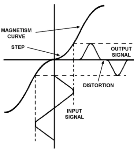
[image:16.612.194.413.277.522.2]The best magnetic recording is the one that produces an output signal identical to the input signal. It didn’t take long to realize that the magnetism generated during the recording process didn’t vary directly to the current which caused it. This is because there’s a step in the magnetism curve where it crosses the zero point and changes polarity. This step causes the output signal to be distorted when compared with the input signal. Figure 1-1 shows this step.
Figure 1-1.—Magnetic recording without bias voltage.
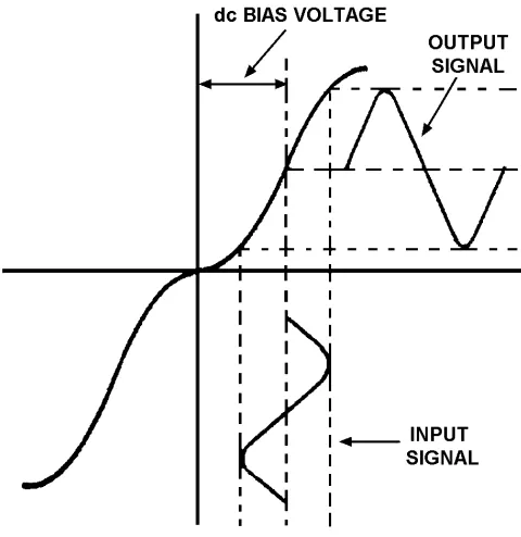
Figure 1-2.—Magnetic recording with dc bias voltage.
Unfortunately, dc bias had its problems. Since only a small portion of the magnetism curve was straight enough to use, the output signal was weak compared with the natural hiss of the unmagnetized tape passing the playback head. This is commonly called poor signal-to-noise ratio (SNR). We’ll explain SNR in more detail later.
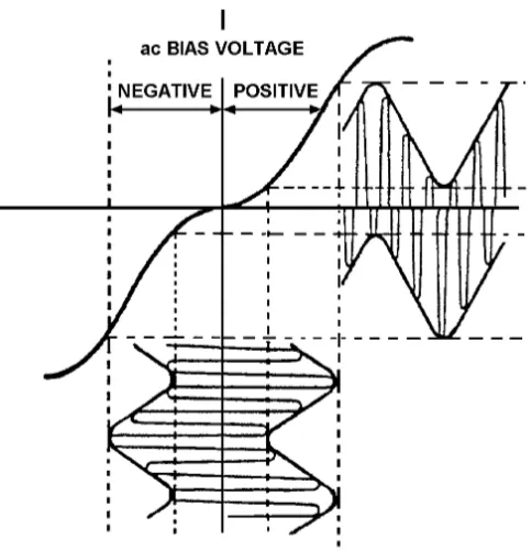
From the beginning, the U.S. Naval Research Laboratories (NRL) saw great potential in magnetic recording. They were especially interested in using it to transmit telegraph signals at high speed. After electronic amplifiers were invented around 1925, W.L. Carlson and G.W. Carpenter at the NRL made the next important magnetic recording discovery. They found that adding an ac bias voltage to the input signal instead of a fixed dc bias voltage would
• reproduce a stronger output signal
• greatly improve the signal-to-noise ratio
• greatly reduce the natural tape hiss that was so common with dc bias
Figure 1-3.—Magnetic recording with ac bias voltage.
Until 1935, all magnetic recording was on steel wire. Then, at the 1935 German Annual Radio Exposition in Berlin, Fritz Pfleumer demonstrated his Magnetophone. It used a cellulose acetate tape coated with soft iron powder. The Magnetophone and its "paper" tapes were used until 1947 when the 3M Company introduced the first plastic-based magnetic tape.
In 1956, IBM introduced the next major contribution to magnetic recording—the hard disk drive. The disk was a 24-inch solid metal platter and stored 4.4 megabytes of information. Later, in 1963, IBM reduced the platter size and introduced a 14-inch hard disk drive.
Until 1966, all hard disk drives were "fixed" drives. Their platters couldn't be removed. Then in 1966, IBM introduced the first removable-pack hard disk drive. It also used a 14-inch solid metal platter.
In 1971, magnetic tape became popular again when the 3M Company introduced the first 1/4-inch magnetic tape cartridge and tape drive. In that same year, IBM invented the 8-inch floppy disk and disk drive. It used a flexible 8-inch platter of the same material as magnetic tape. Its main goal was to replace punched cards as a program-loading device.
The next contribution to magnetic recording literally started the personal computer (PC) revolution. In 1980, a little-known company named Seagate Technology invented the 5-1/4-inch floppy disk drive. Without it, PCs as we know them today would not exist.
From then on, it was all downhill. Magnetic tape became more sophisticated. Floppy disks and disk drives became smaller, while their capacities grew bigger. And hard disk capacities just went through the roof. All of the major hurdles affecting magnetic recording had been successfully cleared, and it was just a matter of refining both its methods and materials.
Q-1. Why did the early inventors of magnetic recording find it necessary to add a fixed dc bias to the input signal?
Q-3. Why does adding dc vice ac bias voltage to the input signal result in a poor signal-to-noise ratio (SNR)?
Q-4. What are three advantages of adding an ac bias voltage to the input signal instead of adding a fixed dc bias voltage?
Q-5. Why does using ac vice dc bias voltage result in a stronger output signal?
PREREQUISITES FOR MAGNETIC RECORDING
To perform magnetic recording, you need three things:
1. An input signal you wish to record.
2. A recording medium. (This is a recording surface that will hold the signal you wish to record.)
3. A magnetic head to convert the input signal into a magnetic field so it can be recorded.
If any one of these are missing, magnetic recording cannot take place.
Input Signal
An input signal can come from a microphone, a radio receiver, or any other source that’s capable of producing a recordable signal. Some input signals can be recorded immediately, but some must be
processed first. This processing is needed when an input signal is weak, or is out of the frequency
response range of the recorder.
Recording Medium
A recording medium is any material that has the ability to become magnetized, in varying amounts, in small sections along its entire length. Some examples of this are magnetic tape and magnetic disks. These are thoroughly discussed in chapter 2 of this module.
Magnetic Heads
Magnetic heads are the heart of the magnetic recording process. They are the transducers that convert the electrical variations of your input signal into the magnetic variations that are stored on a recording medium. Without them, magnetic recording isn’t possible.
Magnetic heads actually do three different things. They transfer, or record, the signal information onto the recording medium. They recover, or reproduce, the signal information from the recording medium. And they remove, or erase, the signal information from the recording medium.
MAGNETIC HEAD CONSTRUCTION.—A magnetic head is a magnetic core wrapped with a
Figure 1-4.—Magnetic field distribution around the head gap.
MAGNETIC HEAD OPERATION.—Whether you're recording on magnetic tapes or disks, all
magnetic heads operate the same way. When an electric current passes through the coil of a magnetic head, magnetic field lines associated with the electric current follow paths through the core material. When the magnetic fields get to the head gap, some of them spread outside the core to form a fringing
field. When a recording medium is passed through this fringing field, it is magnetized in relation to the
electric current. This is called magnetic recording. Figure 1-4 illustrates this process.
Q-6. What three things are required to perform magnetic recording?
Q-7. What is the meaning of the term recording medium as it pertains to magnetic recording? Q-8. What are the three functions of the magnetic heads on a magnetic recording device?
SUMMARY
This chapter briefly covered the historical development of magnetic recording principles and devices. The following is a summary of important points in the chapter.
The BEST MAGNETIC RECORDING is one that produces an output signal that is identical to the input signal. However, a step in the magnetic curve causes the output signal to be distorted.
In 1907, DC BIAS was added to the input signal to remove the distortion in the output signal. But the dc bias caused a weak output signal with a poor SNR. Around 1925, the NRL used AC BIAS to reproduce a stronger output signal and greatly improve the SNR.
To perform magnetic recording, you need (1) an INPUT SIGNAL, (2) a RECORDING MEDIUM, and (3) a MAGNETIC HEAD.
A RECORDING MEDIUM is any material that can become magnetized in varying amounts (such as magnetic tape and disks).
MAGNETIC HEADS are used to (1) record the signal onto the recording medium, (2) reproduce
ANSWERS TO QUESTIONS Q1. THROUGH Q8.
A-1. Because a step in the magnetism curve where it crosses the zero point and changes polarity causes the output signal to be distorted. See figure 1-1.
A-2. The dc bias moves the input signal away from the step in the magnetism curve. This prevents the input signal from crossing the zero-point of the magnetism curve. See figure 1-2.
A-3. With dc bias, the SNR is poor because only a small portion of the magnetism curve is straight enough to use, thus the output signal is weak compared with the natural tape hiss.
A-4.
a. Reproduces a stronger output signal. b. Greatly improves the SNR.
c. Greatly reduces the natural tape hiss.
A-5. Because an ac bias voltage of the proper frequency and level places the input signal away from both steps in the magnetism curve. The result is two undistorted output signals that are combined into one strong output.
A-6.
a. An input signal. b. A recording medium. c. A magnetic head.
A-7. A recording medium is any material that has the ability to become magnetized, in varying amounts, in small sections along its entire length.
A-8.
a. Record the signal onto the recording medium. b. Reproduce the signal from the recording medium.
CHAPTER 2
MAGNETIC TAPE
LEARNING OBJECTIVES
After completing this chapter, you’ll be able to do the following:
1. Describe the physical properties of magnetic tape in terms of:
a. The Three Basic Materials Used To Make Magnetic Tape.
2. The function of the magnetic tape’s base material, oxide coating, and binder glue.
3. Describe the two types of magnetic recording tape.
4. Describe the following types of tape errors and their effects on magnetic tape recording: signal
dropout, noise, skew, and level.
5. Describe the following causes of magnetic tape failure: normal wear, accidental damage,
environmental damage, and winding errors.
6. Describe the purpose and makeup of tape reels and tape cartridges.
7. Describe the two methods for erasing magnetic tape, the characteristics of automatic and manual tape degaussers, and the procedures for degaussing magnetic tape.
8. Describe the proper procedures for handling, storing, and packaging magnetic tape, tape reels, and tape cartridges.
PHYSICAL PROPERTIES OF MAGNETIC TAPE
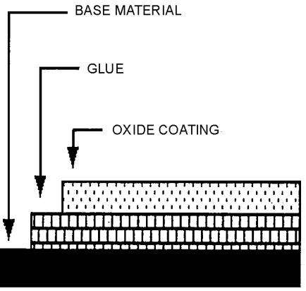
Figure 2-1.—Magnetic tape construction.
BASE MATERIAL
The base material for magnetic tape is made of either plastic or metal. Plastic tape is used more than metal tape because it’s very flexible, it resists mildew and fungus, and it’s very stable at high temperatures and humidity.
OXIDE COATING
Oxide particles that can be magnetized are coated onto the base material. The most common
magnetic particles used are either gamma ferric oxide or chromium dioxide. It’s very important that these magnetic particles are uniform in size. If they’re not, the tape’s surface will be abrasive and will reduce the life of the recorder’s magnetic heads.
An ideal magnetic particle is needle-shaped. It’s actual size depends on the frequency of the signal to be recorded. Generally, long particles are used to record long wavelength signals (low-frequency signals), and short particles are used to record short wavelength signals (high-frequency signals).
GLUE
The glue used to bond the oxide particles to the base material is usually an organic resin. It must be strong enough to hold the oxide particles to the base material, yet be flexible enough not to peel or crack.
TYPES OF MAGNETIC RECORDING TAPE
Digital magnetic tape is also held to much stricter quality control standards. It’s important not to have any blemishes or coating flaws on the tape’s surface. Because, if you lost one digital data bit, your computer program or data would be bad. In contrast, losing one microsecond of an analog signal is not nearly as critical.
Q-1. Magnetic tape is made of what three basic materials? Q-2. Why is plastic magnetic tape used more than metal tape?
Q-3. Which of the two types of magnetic tape is used to record audio and instrumentation type signals in the VLF to 2.5MHz frequency range?
Q-4. What type of magnetic tape is used to record computer programs and data, and what are the additional thickness and quality standards for this type of tape?
TAPE ERRORS AND THEIR EFFECTS
Four types of tape errors that will degrade the performance of a magnetic recording system are signal dropout, noise, skew, and level (signal amplitude changes).
DROPOUT ERRORS
Signal dropout is the most common and the most serious type of tape error. It’s a temporary, sharp drop (50% or more) in signal strength caused by either contaminates on the magnetic tape or by missing oxide coating on part of the tape.
During recording and playback, the oxide particles on the tape can flake off and stick to the recorder’s guides, rollers, and heads. After collecting for awhile, the oxide deposits (now oxide lumps) break loose and stick to the magnetic tape. As the tape with the lumps passes over the head, the lumps get between the tape and the head and lift the tape away from the head. This causes the signal dropouts. Although oxide lumps cause most signal dropouts, remember that any contaminate (such as dust, lint or oil) that gets between the tape and the head can cause signal dropouts.
NOISE ERRORS
Noise errors are unwanted signals that appear when no signal should appear. They’re usually caused by a cut or a scratch on the magnetic tape. It’s the lack of oxide particles at the cut or the scratch that causes the noise error.
SKEW ERRORS
Skew errors only occur on multi-track magnetic tape recorders. The term skew describes the time differences that occur between individual tracks of a single magnetic head when the multi-track tape isn’t properly aligned with the magnetic head.
There are two types of skew errors: fixed and dynamic. Fixed skew happens when properly aligned magnetic tape passes an improperly aligned magnetic head. Dynamic skew happens when misaligned tape passes a properly aligned head. This type of skew is usually caused by one or more of the following:
• A misaligned or worn-out tape transport system.
• A magnetic tape that is improperly wound on a reel.
LEVEL ERRORS
Magnetic tape is manufactured to have a specified output signal level (plus or minus some degree of error). Level errors happen when the actual output signal level either drops or rises to a level outside the expected range. For example, if a magnetic tape is rated for 10 volts ( +/−10%), any output signal level below 9 volts or above 11 volts is a level error. Level errors are caused by an uneven oxide coating on the magnetic tape. This can come from either the original manufacturing process or from normal wear and tear.
Some causes of level errors are permanent and cannot be removed by any means. For example, a crease in the tape, a hole in the oxide, or a damaged edge. Other causes of level errors are removable and may be cleaned off the tape. For example, oxide flakes or clumps, metallic particles, or dirt are
removable.
Q-5. What are four types of tape errors that can degrade a magnetic recording system’s performance? Q-6. What are signal dropouts, and what are two tape defects that can cause signal dropouts?
Q-7. What is the most common and most serious type of signal dropout?
Q-8. You see a build-up of dust and lint on the take-up reel of a tape recorder. This can cause which of the four types of tape errors?
Q-9. What type of tape error causes noise to appear on the tape when no signal should appear? What causes this type of tape error?
Q-10. The multi-track tape recorder in your computer system has a fixed skew error. What does this mean and what is the probable cause?
Q-11. Some tapes you are using may have level errors. What does this mean and what is the cause?
CAUSES OF MAGNETIC TAPE FAILURE
Tape failure happens when a magnetic tape’s performance degrades to a point where it’s no longer usable. The exact point where failure occurs will vary, depending on the type of tape and how it is used.
There are four main causes for tape failure:
1. Normal wear (natural causes)
2. Accidental damage
3. Environmental damage
4. Winding errors
NORMAL WEAR
ACCIDENTAL DAMAGE
Accidental tape damage that causes tape failure is any damage that wouldn’t normally occur under ideal operating and handling conditions. It can be caused by either a human operator or the tape recorder itself. Accidental tape damage caused by human operators can range from accidentally dropping a reel of magnetic tape to improperly threading a magnetic tape recorder. Accidental tape damage caused by recording equipment can occur if the recorder is poorly designed or if the tape transport mechanism is adjusted improperly.
ENVIRONMENTAL DAMAGE
The negative effect of environmental extremes on tape can also cause tape failure. Magnetic tape is very flexible and can be used in a wide range of environmental conditions. It’s designed for use in a temperature range of about 2 to 130 degrees Fahrenheit (−20 to 55 degrees Celsius), and in a relative humidity range of about 10 to 95%. Of course, these numbers are the extreme. Ideally, magnetic tape should be used and stored at a temperature of about 60 to 80º F (room temperature), and in a relative humidity of about 40 to 60%.
Large changes from the ideal relative humidity cause tape to expand or contract and thus affect the uniformity of a tape's oxide coating. High relative humidity causes the tape to stretch and increases the tape's friction. The increased friction causes increased head wear, head clog by oxide particles, and head-to-tape sticking. Low relative humidity encourages oxide shedding and increases static build-up on tape surfaces, causing the tape to collect airborne contaminants.
The effects of exceeding the ideal temperature and humidity ranges described above can cause the following environmental damage to magnetic tape: tape deformation, oxide shedding, head-to-tape
sticking, layer-to-layer sticking, dirt build-up, and excessive tape and head wear.
Tape Deformation
Magnetic tapes are wound onto tape reels with tension applied. This tension causes great layer-to-layer pressure within the reel pack. Changes in temperature and humidity can cause the backing material to expand or contract, creating even more pressure. All of this pressure causes the tape to become deformed or warped.
Oxide Shedding
At temperatures above 130º F, a tape's oxide coating tends to become soft. At temperatures below 2º F, the oxide coating tends to be brittle. In both cases, the oxide coating will shed, flake off, or
otherwise become separated from the base material. These free pieces of oxide will then stick to parts of the tape transport, to the magnetic heads, or back onto the tape and cause dropout or level errors.
Head-to-Tape Sticking
At higher temperatures, the tape binder glue can soften to the point where it will stick to the recorder's magnetic head. This head-to-tape sticking causes jerky tape motion.
Layer-to-Layer Adhesion
Dirt Build-up
Dirt build-up happens when the relative humidity level is less than 10%. The low humidity causes static electricity that attracts dirt and dust which builds up on the magnetic tape and other parts of the magnetic tape recorder.
Excessive Tape and Head Wear
When the relative humidity is more than 95%, the high humidity causes increased friction as the tape passes over the heads. This, in turn, causes excessive tape and head wear.
Q-12. What is tape failure?
Q-13. What are four main causes of tape failure? Q-14. How does normal wear cause tape failure?
Q-15. Accidental damage to magnetic tape is normally caused by the tape recorder itself or by human operators of the recorder. What are three frequent causes of such accidental damage?
Q-16. Environmental damage to magnetic tape can occur when the tape is stored in an area that exceeds what ideal temperature and humidity ranges?
Q-17. What six types of environmental damage can occur to tapes in storage when the ideal temperature and humidity ranges are exceeded?
Q-18. After using a tape that was stored in an area where temperatures exceeded 130º F you notice pieces of oxide sticking to the recorder's tape-transport mechanism, to its magnetic heads, and onto the tape. What is the probable cause of these symptoms?
Q-19. Your activity stores its magnetic tape in an area where the temperature is 100º F. What two types of environmental damage could occur that would make these tapes unusable?
Q-20. When the relative humidity is below 10%, what happens to magnetic tape and parts of a tape recorder that could cause environmental damage?
Q-21. How does relative humidity over 95% cause excessive tape and head wear?
WINDING ERRORS
Winding errors are another cause of tape failure. They happen when improper winding practices create an excessive or uneven force as the tape is being wound onto a tape reel. The form taken by the tape after it is wound onto the reel is called the tape pack. Winding errors can cause a deformed tape pack that will prevent good head-to-tape contact.
In most cases, a deformed tape pack can be fixed simply by rewinding it onto another reel at the proper tension and at the right temperature and humidity. The four most common types of tape pack deformation are:
1. Cinching
2. Pack-slip
4. Windowing
Cinching
Cinching happens when a tape reel is stopped too quickly. The sudden stop causes the outer layers of magnetic tape to continue to spin after the inner layers have stopped. This causes any loosely wound tape within the pack to unwind and pile up. Figure 2-2 shows an example of a cinched tape pack (note the complete foldover of one tape strand).
Figure 2-2.—Example of cinched tape pack.
Pack Slip
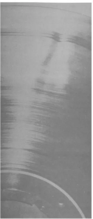
Pack slip happens when the tape is loosely wound on the reel and is exposed to excessive vibration or too much heat. This causes the tape to shift (side-to-side), causing steps in the tape pack. When a tape reel with pack slip is used, the magnetic tape will unwind unevenly and rub against the sides of the tape reel or the recorder’s tape guides. This can damage the magnetic tape and cause oxide shedding. Figure 2-3 shows an example of pack slip.
Spoking
[image:30.612.231.387.192.557.2]Spoking happens when magnetic tape is wound onto the tape reel with the tension increasing toward the end of the winding. The higher tension on the outside of the tape pack causes the inner pack to buckle and deform. Spoking is also caused by the uneven pressures created when a tape is wound on a reel that has a distorted hub, or when the tape is wound over a small particle that is deposited on the hub. Figure 2-4 shows a spoked tape pack.
Figure 2-4.—Example of spoked tape pack.
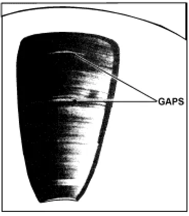
Windowing
Figure 2-5.—Example of windowed tape pack.
Q-22. Tape winding errors can cause a deformed tape pack. What are four common types of tape pack deformation?
Q-23. After rewinding a tape onto its supply reel, you examine the tape pack and notice pile-ups of tape resembling the example in figure 2-2. What causes this condition?
Q-24. You notice steps in the tape pack such as those in figure 2-3. What causes this and how does it damage the magnetic tape?
Q-25. A tape pack is buckled and deformed as shown in figure 2-4. What are three possible causes for this condition?
Q-26. A tape pack has gaps in the tape winding as shown in figure 2-5. What causes this condition?
TAPE REELS AND TAPE CARTRIDGES
There are two types of magnetic tape carriers: tape reels and tape cartridges. Both types can be used for either analog or digital recording. Tape cartridges are normally used only for digital recording.
TAPE REELS
Tape reels are used on magnetic recorders that use a manually loaded tape supply reel and a separate take-up reel. A reel’s purpose is to protect the magnetic tape from damage and contamination. It can be made of plastic, metal, or glass. A reel has two parts, the hub and the flanges.
TAPE CARTRIDGES
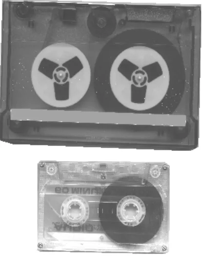
[image:32.612.202.409.172.435.2]Tape cartridges hold a spool of magnetic tape in the same way as tape reels, except that the inside of the cartridge contains both the supply reel and the take-up reel. Unlike tape reels which must be manually loaded into a recorder, when you insert a tape cartridge into a recorder, it’s automatically loaded and ready to use. Figure 2-6 shows two typical tape cartridges.
Figure 2-6.—Typical tape cartridges.
Q-27. When winding a tape onto a plastic or metal reel, should the tape ever touch the reel’s flanges?
TAPE ERASING AND DEGAUSSING
One advantage of magnetic tape is that you can erase what you’ve previously recorded, and record on the same tape again and again. The erasing is done by demagnetizing the magnetic tape. You demagnetize a magnetic tape by exposing it to a gradually decreasing ac (alternating current) magnetic field. There are two ways to do this: (1) with an erase head that’s mounted on the magnetic recorder, or (2) with a separate tape degausser.
ERASE HEADS
A magnetic recorder’s erase head erases magnetic tape by saturating it with an ac signal that’s higher in frequency than the frequency range of the recorder itself. This method of erasing a tape works well in some cases, but it’s not the best way because:
• If the erase head is not completely demagnetized, it may not do a complete erasure.
• Some recorders do not have erase heads installed.
MAGNETIC TAPE DEGAUSSERS
By far, the best way to erase a magnetic tape is to use a separate magnetic tape degausser. There are two types of degaussers: automatic and manual.
Automatic Tape Degausser
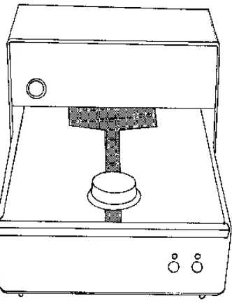
[image:33.612.221.387.282.502.2]Automatic degaussers erase magnetic tape by automatically moving the whole tape reel or cartridge slowly and steadily in and out of an intense ac magnetic field. This type of degausser erases a tape very well. Some automatic degaussers are made specifically for tape reels, and some are made for both tape reels and tape cartridges. Figure 2-7 shows a typical automatic degausser.
Figure 2-7.—Automatic tape degausser.
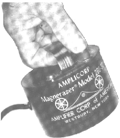
Manual Tape Degausser
Figure 2-8.—Manual tape degausser.
To erase tapes with a manual degausser:
1. Place the tape reel or cartridge to be erased on a flat surface.
2. Hold the degausser very close to the magnetic tape and turn it on.
3. Slowly rotate the degausser in circles around the tape reel or cartridge for a few seconds.
4. Then slowly move it away until you’re about 12 to 14 inches away from the tape reel or tape cartridge.
5. Turn off the degausser.
Q-28. What are two disadvantages of using a recorder’s erase head to erase data recorded on a magnetic tape?
Q-29. What method for erasing magnetic tape is much more effective and reliable than using a recorder’s erase head?
HANDLING, STORING, AND PACKAGING MAGNETIC TAPE
When magnetic tape recordings are ruined, the cause is usually poor handling, improper storage, or shipping damage. If you want your tape recordings to last a long time, you need to know how to properly handle, store, and ship magnetic tape.
HANDLING MAGNETIC TAPE
A magnetic tape reel or cartridge should always be in one of two places, either mounted on a tape recorder or in its storage container. When you handle magnetic tape, follow these rules:
• DO use extreme care when handling magnetic tape. Careless handling can damage magnetic tape, tape reels, and tape cartridges. Always hold a tape reel by the hub, NEVER by the flanges, and NEVER handle or touch the working tape surface.
• DO NOT let the magnetic tape trail on the floor. Even though the end of the tape may not have data stored on it, it can pick up dirt and dust that ends up on the recorder.
• DO clean your hands before handling magnetic tape. You can contaminate magnetic tape with dirt and oils from dirty hands.
• DO mount tape reels and cartridges properly. Improperly seated tape reels can cause unnecessary wear and tear on the magnetic tape.
• DO replace any warped take-up reels, as they can damage magnetic tape.
• DO keep the magnetic recorder and its take-up reel clean. Magnetic tape can pick up dirt and dust from the recorder itself.
• DO NOT use the top of a magnetic recorder as a work area. This can expose the magnetic tape to dirt, excessive heat, and stray magnetic fields.
• DO NOT allow eating, drinking, or smoking in areas where magnetic tape or devices are exposed.
STORING MAGNETIC TAPE
Most magnetic tape reels and cartridges spend a lot of time in storage. It’s very important that you protect the stored tape from physical damage and the damaging effects of contamination and temperature and humidity extremes. If you don’t, damage to the tape pack such as oxide shedding, layer-to-layer sticking, and tape deformation can happen. To protect magnetic tape from damage during storage, follow these rules:
• DO make sure that magnetic tape is wound properly on the reel hub and at the proper tension.
• DO always store tape reels vertically. DO NOT lay them on their side.
• DO maintain a proper environment. Keep the storage area clean, and at a 60 to 80F degree temperature and a 40 to 60% relative humidity.
• DO NOT store magnetic tapes near any equipment that generates stray magnetic fields.
• DO handle all tape reels and cartridges as gently as possible.
PACKAGING MAGNETIC TAPE FOR SHIPPING
There may be times when you are asked to package magnetic tape reels or tape cartridges for shipment. If you want the tape to arrive in good condition, you must pack it properly to protect it from damage. The packaging you use must protect the tape reels or cartridges from impact, vibration, and temperature and humidity changes. Here are some simple rules to follow:
• DO always package tape reels so that they’re supported by their hub. This prevents any pressure on the reel’s flanges that might flex the flanges against the tape pack. Figure 2-9 shows a shipping box that supports the tape reel by the hub.
Figure 2-9.—Reel box that supports reel by the hub.
• DO always use reel bands where available. Reel bands are for placement around the outside edges of the reel flanges to help prevent the flanges from flexing and damaging the tape.
• DO always ship magnetic reels in a container designed so its normal positioning is with the reels in a vertical position. This will prevent the tape pack from shifting and damaging the edges of the magnetic tape.
• DO always package tape cartridges in their shipping cases. Tape cartridges are more durable than tape reels, but they still need to be protected during shipment.
Q-30. When magnetic tapes are ruined, what three factors are normally the cause? Q-31. What is the correct way to hold a magnetic tape reel?
Q-32. The take-up reel on your recorder is warped. What should you do to/with the reel?
Q-33. If magnetic tape is stored in areas with temperature and humidity extremes, what are three types of tape damage that may occur?
Q-34. List four rules you should follow when storing magnetic tape to protect it from damage. Q-35. When packaging tape reels or cartridges for shipping, what are four rules you should follow to
SUMMARY
Now that you’ve finished chapter 2, you should be able to (1) describe the physical properties of magnetic tape, (2) recognize the four most common magnetic tape errors, (3) recognize the four causes of tape failure, (4) describe the two methods for erasing magnetic tape, and (5) use the proper procedures for handling, storing, and packaging magnetic tape, tape reels, and tape cartridges. The following is a
summary of the important points in this chapter.
The three BASIC MATERIALS used to make magnetic tape are the (1) base material, (2) the oxide particles, and (3) the binder glue.
ANALOG and DIGITAL are the two basic types of magnetic tape in common use.
BLEMISHES OR COATING FLAWS ON DIGITAL TAPE can easily ruin the data or the
computer program stored on the tape.
SIGNAL DROPOUT, NOISE, SKEW, AND LEVEL are four types of tape errors. Dropout errors
are the most common.
OXIDE LUMPS accumulated on the tape cause most dropout errors. Other causes are dust or lint
on the tape, or missing oxide coating on part of the tape.
MAGNETIC TAPE FAILURE has four main causes: (1) normal wear, (2) accidental damage,
(3) environmental damage, and (4) winding errors.
IDEAL TEMPERATURE AND HUMIDITY RANGES for using and storing magnetic tape are
60 to 80º F and 40 to 60% relative humidity.
ENVIRONMENTAL TAPE DAMAGE caused by excessive temperature or humidity includes the
following: (1) tape deformation, (2) oxide shedding, (3) head-to-tape sticking, (4) layer-to-layer sticking, (5) dirt buildup, and (6) excessive tape and head wear.
WINDING ERRORS can cause tape pack deformation. The four most common types are:
(1) cinching, (2) pack slip, (3) spoking, and (4) windowing.
The TWO PARTS OF A TAPE REEL are the hub and the flanges. The tape should be wound on the hub. No part of the tape should be touching the flange sides.
ERASE HEADS AND TAPE DEGAUSSERS are two methods for erasing tape. Degaussers are
the fastest and the most reliable.
Rules for HANDLING MAGNETIC TAPE are (1) always hold the reel by the hub, not the flanges, (2) never touch the working tape surface, (3) replace warped or damaged reels, and (4) mount reels and cartridges properly.
Rules for STORING MAGNETIC TAPE are (1) wind tape properly on the reel hub, (2) store tapes vertically, (3) keep storage area clean and at proper temperature and humidity levels, and (4) store tapes away from equipment that generates stray magnetic fields.
ANSWERS TO QUESTIONS Q1. THROUGH Q35.
A-1.
a. Base material.
b. Coating of magnetic oxide particles. c. Glue that bonds the particles to the base.
A-2. Plastic tape is used more than metal because it’s more flexible, resists mildew and fungus, and is very stable at high temperatures and humidity.
A-3. Analog magnetic tape.
A-4. Digital magnetic tape is for computer programs and data. Its base material is about 50% thicker. The tape’s surface must not have blemishes or coating flaws because losing even one digital data bit could ruin the recorded computer program or data.
A-5. Signal dropout, noise, skew, and level. Dropout is the most common.
A-6. Dropouts are temporary, sharp drops (50% or more) in signal strength. They’re caused by contaminates that lift the tape away from the magnetic head, or when magnetic oxide coating is missing on part of the tape.
A-7. Oxide particles that get onto the magnetic tape.
A-8. Signal dropout errors and level errors. The dust and lint on the reel will eventually get onto the tape where it can get between the tape and the recorder’s heads.
A-9. Noise error is usually caused by a cut or a scratch on the magnetic tape.
A-10. Skew means there are time differences between the individual tracks of a multi-track recorder’s magnetic head. It happens when the tape isn’t properly aligned with the head. Fixed skew happens when the tape passes over an improperly aligned magnetic head.
A-11. The actual output signal level of the tape exceeds the manufacturer’s specified range for the output signal level (+ / − 10%). It’s caused by an uneven oxide coating on the tape due to worn tape or defective manufacture.
A-12. Tape’s performance degrades to a point where it’s no longer usable.
A-13. Normal wear, accidental damage, environmental damage, and winding errors.
A-14. Repeated contact with a recorder’s fixed surfaces such as magnetic heads, tape rollers, and tape guides.
A-15.
a. Improperly adjusted tape transport mechanism. b. Dropping a reel of tape.
A-16. Ideally, use and store tape at 60 to 80º F and at 40 to 60% relative humidity.
A-17. Tape deformation, oxide shedding, head-to-tape sticking, layer-to-layer sticking, dirt build-up, and excessive tape and head wear.
A-18. Oxide shedding. At temperatures above 130º F, oxide coating becomes soft and sheds. A-19. Head-to-tape sticking and layer-to-layer adhesion.
A-20. Dirt build-up caused by static electricity.
A-21. High humidity causes increased friction as the tape passes over the heads. A-22. Cinching, pack slip, spoking, and windowing.
A-23. The tape is stopped too quickly when winding or rewinding.
A-24. Pack slip. It's caused by loosely wound tape on a reel that is exposed to excessive vibration or heat. The vibration or heat causes the tape to shift, causing steps in the tape pack. The uneven tape will then rub against the reel's sides and the recorder's tape guides.
A-25.
a. Reel has a distorted hub,
b. tape wound over small particle deposited on hub, and
c. tape wound on reel with tension increasing toward end of winding. A-26. Tape is loosely wound on reel.
A-27. No. The reel is designed to hold the tape on its hub without letting the tape touch the sides of the flanges.
A-28. Using an erase head is slow, and it may not completely erase the tape. A-29. Using a magnetic tape degausser.
A-30. Poor handling, improper storage, or shipping damage.
A-31. Always hold reel by the hub, never by the flanges. Never touch the working tape surface. A-32. Always replace a warped reel.
A-33. Oxide shedding, layer-to-layer sticking, and tape deformation. A-34.
a. Make sure the tape is wound properly on the reel hub, b. store tapes vertically,
c. keep storage area at right temperature and humidity,
A-35.
a. Package reels so they’re supported by their hub, b. use reel bands,
c. package reels in vertical position,
CHAPTER 3
MAGNETIC TAPE RECORDER HEADS
LEARNING OBJECTIVES
After completing this chapter, you'll be able to do the following:
1. Describe the construction, function, and placement of magnetic tape recorder record, reproduce, and erase heads.
2. Describe the preventive maintenance requirements for magnetic tape recorder heads.
MAGNETIC TAPE RECORDER HEADS
Magnetic tape recorder heads are the heart of magnetic tape recording, because it's the magnetic heads (as we'll call them in this chapter) that actually:
1. Record signal or data information onto magnetic tape
2. Reproduce (play back) signal or data information from magnetic tape
3. Erase any signal or data off of magnetic tape
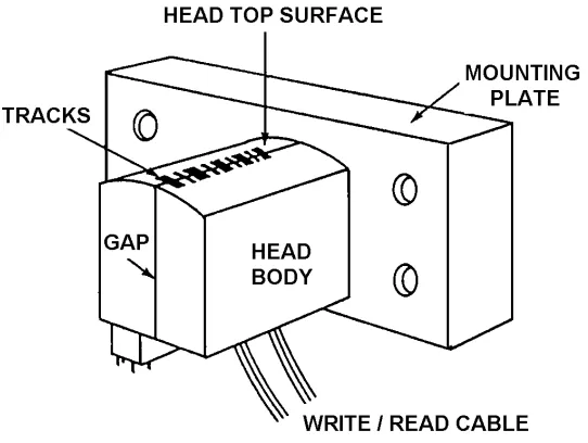
[image:41.612.174.445.485.689.2]To do these things, a magnetic tape recorder can have up to three different heads installed: one head for recording, one for reproducing, and one for erasing. Some magnetic tape recorders will use the same head for both recording and reproducing. Figure 3-1 shows a typical multitrack magnetic head.
MAGNETIC HEAD CONSTRUCTION
Magnetic head construction is basically the same for all magnetic heads. They're all made up of a magnetic core wrapped with a coil of very thin wire. But, there's where the similarity ends. From here on, each magnetic head is built to perform a specific job. Will the head be used on a single track recorder? Will it be used on a multitrack recorder? Will it be a record head or a reproduce head? Or, will it be an erase head? What frequency will it be recording and/or reproducing? The answers to these questions will determine the final construction of a magnetic head.
[image:42.612.141.477.280.690.2]Figure 3-2 shows the construction of a typical multitrack magnetic head. Magnetic cores are wound with very thin wire, cemented together, and placed inside a half-bracket. A tip piece is then placed on top of the ferrite core, and the two half-brackets are assembled together. It's during this final assembly process that the headgap and the resulting frequency response of the magnetic head are determined. After some final contouring to give the magnetic head its curved face, it's ready for use.
Record and Reproduce Heads
Record and reproduce heads convert and transfer electrical signals onto and off of magnetic tape. The maximum frequency these heads can transfer depends on the size of the headgap and the speed of the magnetic tape (we'll discuss speed in the next chapter). Most record and reproduce heads are in one of these three general bandwidth categories:
1. Narrowband—100 Hz to 100 kHz
2. Intermediate band—100 Hz to 500 kHz
3. Wideband—400 Hz to 2 mHz
The only physical difference between a record head and a reproduce head is in the number of turns of wire on the core. A reproduce head will have more turns than a record head. This is because reproduce heads must be able to recover low-level signals from magnetic tape. The extra turns of wire allow the reproduce head to output the highest level possible and at a good signal-to-noise level.
Record heads are always placed before reproduce heads on magnetic tape recorders. This allows you to monitor signals that you're recording. Figure 3-3 shows the placement of record and reproduce heads. Figure 3-4 shows some of the typical track arrangements used.
Figure 3-4.—Magnetic head track placement.
Erase Heads
Erase heads transfer a signal to the magnetic tape that causes the magnetic particles to assume a neutralized or erased state. To do this, a high current signal that is 3 to 5 times higher in frequency than the maximum frequency response of the record and reproduce heads is used. In some audio recorders, a simple direct current (dc) voltage is used.
Erase heads are always placed before the record and the reproduce heads on tape recorders. This allows you to erase the magnetic tape before it's recorded on. Figure 3-3 shows the placement of erase heads.
Q-1. Magnetic tape recorders can have up to three different heads installed. What are the three functions performed by a recorder's heads?
Q-2. The way a magnetic head will be used determines how it is constructed. Name three factors that determine the final construction of a magnetic head.
Q-3. What two specifications determine the maximum frequency that a recorder's record and reproduce heads will be able to transfer?
Q-4. Most record and reproduce heads are in one of what three bandwidth categories?
Q-5. Why are record heads always placed before reproduce heads on recorders?
MAGNETIC HEAD MAINTENANCE
It's very important to regularly maintain magnetic heads. If you do, you'll greatly reduce the chance of getting a poor recording or playback. Regular preventive maintenance will also increase the life of the magnetic heads. There are two things you must do to properly maintain magnetic heads: (1) keep them clean, and (2) keep them demagnetized.
Cleaning Magnetic Heads
Through use, magnetic heads pick up dirt, dust, lint, and oxide particles from the magnetic tape. These particles collect on the magnetic head and, if left unchecked, could cause signal dropout errors that degrade the quality of recording and playback. To keep magnetic heads clean, regularly clean them with a cotton-tipped applicator soaked in either isopropyl alcohol or in a magnetic head cleaner recommended by the recorder's manufacturer. A good rule of thumb is to clean the heads each time you change a tape reel or cartridge.
Demagnetizing Magnetic Heads
Magnetic heads can become magnetized from many sources. It could happen
• during ac power losses,
• during testing or alignment,
• because of stray magnetic fields,
• from normal use.
No matter the cause, magnetized magnetic heads degrade the quality of the magnetic recording or playback.
Figure 3-5.—Hand-held head degausser.
The procedure for demagnetizing a magnetic head is similar to the procedure for degaussing a magnetic tape. Here are the basic steps:
1. Remove the tape (reel or cartridge) from the magnetic recorder.
2. Holding the degausser an arm's length away from the magnetic head, energize the degausser.
3. Slowly bring the degausser closer and closer to the magnetic head. Don't touch the head with the degausser.
4. Move the degausser back and forth across the head for 15 to 30 seconds. Figure 3-6 shows how this looks.
Figure 3-6.—Demagnetizing magnetic heads with a degausser.
That's all there is to it. It's hard to determine exactly how often magnetic heads should be
de-magnetized. Manufacturer's recommendations vary from every 8 to 25 hours of operation. To be safe, check the equipment's technical manual.
Q-7. What two preventive maintenance actions must you do regularly to increase magnetic head life and to ensure good tape recording and playback?
Q-8. How should you clean your recorder's magnetic heads?
Q-9. What are four sources that can cause magnetic heads to become magnetized?
Q-10. What type of equipment should you use to demagnetize your recorder's magnetic heads?
Q-11. How often should you demagnetize a recorder's magnetic heads?
SUMMARY
Now that you've finished chapter 3, you should be able to (1) describe the construction of magnetic tape recorder heads; (2) describe the purpose and placement of record, reproduce, and erase heads; and (3) describe the preventive maintenance requirements for tape recorder heads. The following is a summary of important points in this chapter:
Magnetic tape recorders have up to THREE MAGNETIC HEADS to perform the erase, record, or reproduce function.
Most tape recorder heads are designed for ONE OF THREE BANDWIDTHS: (1) narrowband, (2) intermediate band, or (3) wideband.
A recorder's magnetic heads are in the following SEQUENCE on its record/reproduce track: (1) erase, (2) record, and (3) reproduce.
Two important PREVENTIVE MAINTENANCE requirements for magnetic heads are cleaning and demagnetizing.
ANSWER TO QUESTIONS Q1. THROUGH Q11.
A-1. Record, reproduce, and erase.
A-2.
a. Type of head (record, reproduce, or erase).
b. Frequencies it will record or reproduce.
c. Whether it will be used on a single or multitrack recorder.
A-3.
a. Size of the headgap.
b. Speed of the magnetic tape.
A-4.
a. Narrowband—100 Hz to 100 kHz.
b. Intermediate band—100 Hz to 500 kHz.
c. Wideband—400 Hz to 2 mHz.
A-5. Allow you to monitor the signals you're recording.
A-6. First, before the record and reproduce heads.
A-7.
a. Keep the heads clean.
b. Keep the heads demagnetized.
A-9.
a. During ac power losses.
b. During testing.
c. Because of stray magnetic fields.
d. From normal use.
A-10. A hand-held degausser like the manual degaussers used for degaussing magnetic tape.
CHAPTER 4
MAGNETIC TAPE RECORDER TRANSPORTS
LEARNING OBJECTIVES
After completing this chapter, you'll be able to do the following:
1. Describe the function and components of a basic magnetic tape transport system.
2. Describe the operating characteristics and parts of the three most common tape reeling systems.
3. Describe the physical characteristics of the two basic tape reeling configurations, co-planar and co-axial.
4. Describe the characteristics of open-loop drive and closed-loop drive tape transport configurations and the three most common closed-loop designs.
5. Describe the capstan speed control function of a tape transport system and the relationship of the six basic parts of a typical capstan speed control unit.
6. Explain why, and describe how, magnetic tape transports must be cleaned and degaussed.
INTRODUCTION
Magnetic tape recorder transports are precisely built assemblies that move the magnetic tape across the magnetic heads and hold and protect the tape. Figure 4-1 shows a basic tape transport assembly. Tape transports have four basic parts:
1. A tape reeling system that, with the aid of tape guides, physically moves the tape across the magnetic heads.
2. A tape speed control system that monitors and controls the movement of the magnetic tape. 3. An electronic subsystem that activates the reeling device to move the magnetic tape. 4. A basic enclosure that holds and protects the reels or cartridges of magnetic tape.
This chapter describes these basic parts, tells how they work, and shows diagrams of the more common ones.
TAPE REELING SYSTEMS
A basic magnetic recorder tape reeling system (figure 4-1) has one supply reel and one take-up reel. Its job is to move the magnetic tape from one reel to the other. When this happens, four things occur:
1. The supply reel feeds out magnetic tape at a constant tension.
2. The tape passes the magnetic heads in a straight line.
3. The take-up reel accepts the magnetic tape at a constant tension.
4. Both the supply and take-up reels start and stop smoothly while maintaining the proper tape tension.
These four things must happen, or the magnetic tape could be damaged. Three of the most commonly used tape reeling systems are (1) take-up control, (2) two-motor reeling, and (3) tape buffering.
TAKE-UP CONTROL REELING SYSTEMS
This system uses a motorized take-up reel which pulls the magnetic tape off of a free-spooling supply reel. It maintains tape tension by using mechanical drag on the supply reel. As you might guess, this method has its disadvantages. It only works in one direction, and the tape tension doesn't remain constant throughout the reel. As the supply reel gives out tape, the tape tension varies. Uneven tape tension can cause stretched tape, poorly wound tape reels, and tape damage during starts and stops.
TWO-MOTOR REELING SYSTEMS
To overcome the problems of take-up control reeling systems, designers added a motor to the supply reel. By using two motors, the magnetic tape direction can be forward or reverse.
Two-motor reeling configurations usually use dc (direct current) motors, instead of ac (alternating current) motors, because dc motors run smoother and are easier to control. To help control tape tension, a small hold-back voltage is added to the motor for the supply reel.
TAPE BUFFERING REELING SYSTEMS
Controlling a recorder's tape tension during starts and stops is a big problem. Tape buffering overcomes this problem by regulating the tape reel speed and by pro