141
©IJRASET: All Rights are Reserved
Simulation based Analysis of Space Vector Pulse
Width Modulation (SVPWM) in AC Drives
Showkat Ahmad Wani1, Er. Navnidhi Sharma2 1, 2
Department of Electrical Engineering, E-max Group of Institutions, Ambala
Abstract: Since a solid state transformer is a three stage AC/AC converter with a high frequency transformer and because of advanced features like high power density, on demand var support and frequency control, solid state transformer is an empowering innovation for the advanced power distribution systems. It can likewise discover application in high power density engine drives. The single stage solid state transformer considered in this work is equipped for bidirectional power stream and open loop power factor rectification. This topology utilizes a base measure of copper and has generally few semiconductor switches. In this work we exhibit a novel modulation SVPWM system utilizing Solid State Transformer for AC drives. Multilevel inverters produce sinusoidal voltages from discrete voltage levels, and pulse width modulation (PWM) methodologies achieve this assignment of creating sinusoids of variable voltage and frequency. Modulation techniques for Hybrid Multilevel Inverter can be according to the switching frequency strategies. A wide range of PWM techniques have been developed to accomplish the following: wide linear modulation range, low switching loss, diminished Total Harmonic Distortion (THD) in the spectrum of switching waveform: and simple usage and less calculation time. The most generally utilized methods for executing the pulse width modulation (PWM) procedure for multilevel inverters are Sinusoidal PWM (SPWM) and space vector PWM (SVPWM). The SVPWM is considered as a superior method of PWM usage as it has points of interest over SPWM as far as great use of dc bus voltage, diminished switching frequency and low current ripple is displayed. SVPWM can be effectively executed in a couple of microseconds, accomplishing comparative outcomes compared with other PWM strategies.
Keywords: SVPWM, SST, THD, AC Drives, VSI.
I. INTRODUCTION
142
©IJRASET: All Rights are Reserved
awesome endeavors are as yet required toward the fast advancement of the SST [2,3]. To direct the plan of the SST in the power distribution networks, a survey of the best in class innovation of the distribution transformers, including proficiency, volume and weight, and cost, is at first introduced.
II. SPACEVECTORMODULATION
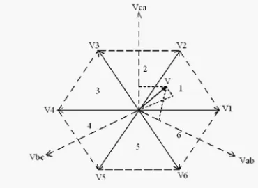
[image:2.612.169.469.190.304.2]The coveted three stage voltages at the yield of the inverter could be spoken to by a proportional vector V pivoting in the counter clock astute bearing as appeared in Figure 4.6.a. The greatness of this vector is identified with the size of the yield voltage as appeared in Figure 4.6.b and the time this vector takes to finish one upset is the same as the crucial day and age of the yield voltage.
[image:2.612.233.412.355.492.2]Figure 1 Zero Output Voltage Topologies
Figure 2 Representation of the zero voltage vectors in the , plane
At the point when the coveted line-to-line yield voltage vector V is in part 1 as appeared in Figure 4.7., vector V could be blended by the beat width balance (PWM) of the two contiguous exchanging state vectors V1 (pnn) and V2 (ppn), the obligation cycle of each being d1 and d2, individually, and the zero vector (V7 (nnn)/V8 (ppp) ) of obligation cycle d0
[image:2.612.220.405.575.710.2]143
[image:3.612.149.471.84.269.2]©IJRASET: All Rights are Reserved
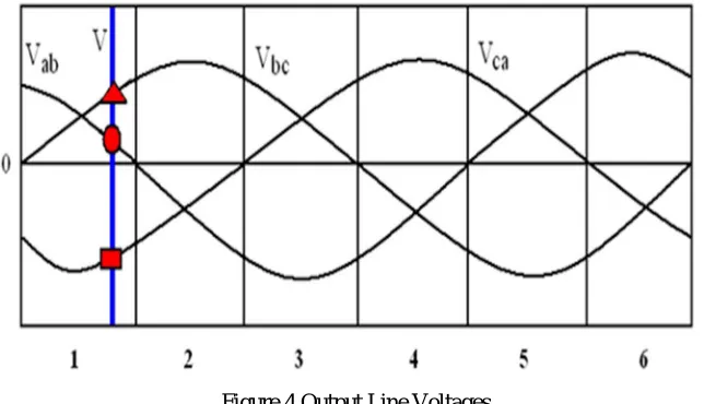
Figure 4 Output Line Voltages
[image:3.612.189.435.395.550.2]Where, 0 m 0.850 is the adjustment file. This would relate to a most extreme line-to-line voltage of 1.0Vg, which is 15% more than customary sinusoidal PWM. All SVPWM plans and the greater part of the other PWM calculations, utilize the Equations 4.3 and 4.4 for the yield voltage blend [4]. The adjustment calculations that utilize non-neighboring exchanging state vectors have been appeared to deliver higher THD and additionally exchanging misfortunes. However, some of them, for e.g. hysteresis balance, can be extremely easy to actualize and can give quicker transient reaction. The obligation cycles d1 , d2 and d0 , are particularly decided from Figure 4.7, and the conditions of 4.3 and 4.4, the main contrast between PWM plans that utilization nearby vectors is the decision of the zero vector(s) and the arrangement in which the vectors are connected inside the exchanging cycle.
Figure 5 Synthesis of the Required Output Voltage Vector in Sector 1
A. General Structure Of The Space Vector Modulation Algorithm
144
[image:4.612.198.428.78.256.2]©IJRASET: All Rights are Reserved
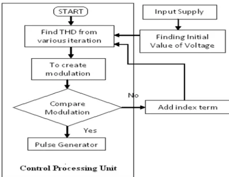
Figure 6 Flowchart of the Algorithm
│m-mc│<
where,
− Reference value increases (or) decreases the pulse generation in the pulse generator.
In the event that the contrast between the two regulation record terms is not as much as reference esteem , the proposed calculation yields the ideal exchanging edges. The cycle strategy is utilized to illuminate and discover minimization of the voltage THD.
III.SPACEVECTORPULSEWIDTHMODULATIONFORSST
Staggered inverters create sinusoidal voltages from discrete voltage levels, and heartbeat width regulation (PWM) methodologies achieve this errand of producing sinusoids of variable voltage and recurrence. Balance techniques for Hybrid Multilevel Inverter can be ordered by the exchanging recurrence strategies. A wide range of PWM strategies have been created to accomplish the accompanying: Wide straight regulation range, less exchanging misfortune, diminished Total Harmonic Distortion (THD) in the range of exchanging waveform: and simple execution and less calculation time. The most generally utilized procedures for actualizing the beat with adjustment (PWM) technique for staggered inverters are Sinusoidal PWM (SPWM) and space vector PWM (SPWM). The SVPWM is considered as a superior procedure of PWM usage as it has favorable circumstances over SPWM as far as great use of dc transport voltage, decreased exchanging recurrence and low current swell [6]. SVPWM is viewed as a superior procedure of PWM execution, as it gives the accompanying points of interest,
1) Better key yield voltage.
2) Useful in enhancing consonant execution and decreasing THD.
3) Extreme straightforwardness and its simple and direct equipment execution in a Digital Signal Processor (DSP).
4) SVPWM can be productively executed in a couple of microseconds, accomplishing comparative outcomes contrasted and other
PWM techniques.
145
©IJRASET: All Rights are Reserved
gadgets. Notice that these 3-D OSVPWM procedures can be connected with adjusted and lopsided frameworks. Execution of the 2-D SVPWM and 3-2-D OSVPWM methods is completed. Both SVPWM calculations are actualized into a Field Programmable Gate Arrays (FPGA) from Xilinx Foundation [9]. MATLAB Simulink is utilized to build up all recreation works. At long last, both algorithmic usages have been tried with a fell H-connect staggered inverter.
IV.RESULTS
MATLAB is a great dialect for specialized processing. The name MATLAB remains for Matrix Laboratory, since its essential information component is a lattice (cluster). It is fourth era of abnormal state programming dialect for math calculations, displaying and reproductions, information examination and preparing, perception and designs, and calculation advancement.
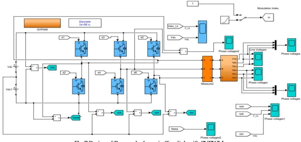
[image:5.612.68.561.219.452.2]A. SST SVM Model
[image:5.612.188.435.503.708.2]Fig 7 Design of Proposed scheme in Simulink with SVPWM
Fig 7 shows the simulink model of SVPWM ac drive. Model has been drawn on MATLAB. In the next stage output has also been shown.
146
©IJRASET: All Rights are Reserved
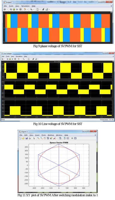
Fig 9 phase voltage of SVPWM for SST
[image:6.612.120.502.76.741.2]Fig 10 Line voltage of SVPWM for SST
147
[image:7.612.145.479.75.301.2]©IJRASET: All Rights are Reserved
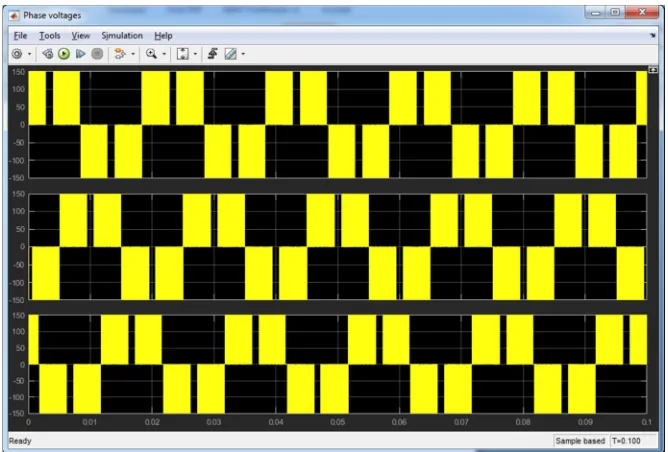
Fig 12 Phase voltage of SVPWM After switching modulation index to 1
Fig 13 Line voltage of SVPWM After switching modulation index to 1
V. CONCLUSION
[image:7.612.139.487.324.512.2]148
©IJRASET: All Rights are Reserved
VI.ACKNOWLEDGEMENT
I concede the way my guide Er. Navnidhi Sharma played an important role in carrying out this work and all those difficult times when it was looking like a blind alley. She gave me confidence and motivated me to take up this work. All my toiling efforts were based on her motivation. Finally, i would like to mention my parents which are the be-all and end-all inspirations and motivations to me.
REFERENCES
[1] Zhan, C., Ramachandaramurthy, V. K., Arulampalam, A., Fitzer, C., Kromlidis, S., Bames, M., and Jenkins, N. (2001). Dynamic voltage restorer in view of voltage-space-vector PWM control. IEEE exchanges on Industry applications, 37(6), 1855-1863.
[2] Fang, X. P., Qian, Z. M., and Peng, F. Z. (2005). Single-stage Z-source PWM air conditioning air conditioning converters. IEEE Power Electronics Letters, 3(4), 121-124.
[3] Iman-Eini, H., & Farhangi, S. (2006, June). Analysis and design of power electronic transformer for medium voltage levels. In Power Electronics Specialists Conference, 2006. PESC'06. 37th IEEE (pp. 1-5). IEEE.
[4] Falcones, S., Mao, X., & Ayyanar, R. (2010, July). Topology comparison for solid state transformer implementation. In Power and Energy Society General Meeting, 2010 IEEE (pp. 1-8). IEEE.
[5] Abramovitz, A., & Smedley, M. (2012). Survey of solid-state fault current limiters. IEEE Transactions on power electronics, 27(6), 2770-2782.
[6] She, X., Huang, A. Q., Lukic, S., & Baran, M. E. (2012). On integration of solid-state transformer with zonal DC microgrid. IEEE Transactions on Smart Grid, 3(2), 975-985.
[7] Qin, H., & Kimball, J. W. (2013). Solid-state transformer architecture using ACûAC dual-active-bridge converter. IEEE Transactions on Industrial Electronics, 60(9), 3720-3730
[8] G. Guerra and J. A. Martinez-Velasco, “A solid state transformer model for power flow calculations,” Electrical Power and Energy Systems, vol. 89, pp. 40– 51, Jan. 2017.