Abstract—For CNC machine tools with synchronized motion axes, existing feedforward motion control designs are usually employed for reducing tracking errors and thus achieving desired tracking accuracy. However, the contouring accuracy of motion control design remains limited mainly because of unmatched dynamics among all motion axes. In this study, a feedforward motion control design was developed by considering the mutual dynamics among all the motion axes for improving contouring accuracy. Applying stable pole-zero cancellation to each axis and compensating phases for the uncancelled zeros of all axes led to matched dynamic responses for all the motion axes across the entire frequency range, thus ensuring contouring accuracy. Moreover, a digital disturbance observer was developed to repress adverse effects induced by model uncertainties and external disturbances, for the enhancement of motion robustness in real applications. Finally, experiments performed on a 3-axis CNC milling machine validated both the proposed feedforward motion control design and the digital disturbance observer design.
Index Terms—Feedforward Control, Motion Control, Contouring Accuracy, CNC machine tools
I. INTRODUCTION
NE of the most important requirements of precision CNC machining is motion accuracy, which is usually characterized in the motion control system by its tracking accuracy and contouring accuracy. However, in practice, certain factors can significantly degrade motion accuracy, including the following: (a) external disturbances such as cutting force, friction, and external force and torque perturbations; (b) inherent characteristics of servo systems such as servo lag and mismatched dynamic properties among synchronized motion axes; and (c) model uncertainties in the motion control design.
Generally, the performance of motion control systems that have an appropriate feedback and feedforward control design is highly dependent on both tracking accuracy and contouring accuracy. Poo et al. [1] analyzed the relations between
Manuscript received December 8, 2012. This project is supported in part by the National Science Council of the Republic of China under Contract NSC 101-2221-E-027-031 and the Industrial Technology Research Institute, ROC, under project number B353C72000, which is subcontracted from the Ministry of Economic Affairs, ROC.
Syh-Shiuh Yeh is with the National Taipei University of Technology, Taipei, Taiwan (phone: +886-2-27712171; fax: +886-2-27317191; e-mail: [email protected]).
Jin-Tsu Sun is with the Industrial Technology Research Institute, Taichung, Taiwan (e-mail: [email protected]).
feedback controllers and contouring errors. Later, feedforward control loops began to be discussed in motion control systems because they efficiently reduce servo lags [2-5] and passively decrease contouring error. In addition to well-designed feedback and feedforward control loops, a cross-coupled control (CCC) structure, which considers the mutual dynamic effects among all axes, was developed by Koren [6] to reduce contouring error. Various improved CCC designs have since been proposed [7-11]. For significantly improving both tracking and contouring accuracy, Lo [12] proposed transforming coordinates to obtain a moving basis in order to create a feedback controller for 3-axis motion systems. Chiu and Tomizuka [13] proposed a task-coordinated approach by considering all axes as first-order loops to obtain feedback and feedforward control loops. Yeh et al. [14] further applied an integrated control structure to achieve high tracking and contouring precision.
Although many advanced control algorithms and structures have been developed for simultaneously improving the tracking accuracy and contouring accuracy of multi-axis motion control systems, conventional control structures with feedback and feedforward controllers remain the most fundamental and crucial factor in obtaining desirable motion accuracy. Theoretically, to improve the contouring accuracy of multi-axis motion control systems, feedback controllers should be designed to achieve matched dynamic characteristics among all motion axes. Then, the feedforward control is applied to further improve tracking accuracy. Poo et al. [1] proposed a design with constant gains matched between two motion axes; however, such a design is not applicable to complex plants that usually have higher-order models and that operate under high speed. In recent decades, feedforward control design with zero-phase error tracking controller (ZPETC) has received considerable attention in positioning applications because it provides good tracking accuracy in motion systems. ZPETC [2] renders the desirable zero-phase error but with a limited gain response. Although an optimal ZPETC design with a concise polynomial digital pre-filter [4, 5] can be applied toward extending the bandwidth for a single axis, unmatched dynamics among all axes still limit the contouring responses.
In our study, a novel feedforward motion control design was developed in order to significantly improve both the tracking accuracy and the contouring accuracy for multi-axis motion control systems with conventional PID feedback controllers [15]. By applying stable pole-zero cancellation to individual axes and by employing complementary zeros for
Feedforward Motion Control Design for
Improving Contouring Accuracy of CNC
Machine Tools
Syh-Shiuh Yeh and Jin-Tsu Sun
all uncancelled zeros among all axes, we developed the feedforward motion control design for achieving identical frequency responses for different motion axes. Thus, we expected that, besides good tracking responses, it would also achieve good contouring responses. We optimized the feedforward motion control design by cascading our feedforward controller with a digital pre-filter in which its parameters were obtained through applying L2-norm
optimization. The resultant optimal feedforward motion control design greatly improved the bandwidth of a multi-axis motion control system while maintaining matched frequency responses among all synchronized motion axes.
Because a model-based motion control design is usually sensitive to external disturbances and model uncertainties in real applications, a disturbance observer has been employed to reduce the adverse effects of such undesirable influences [16-18]. Although this disturbance observer has been successfully applied to motion control systems and has shown good performance in reducing external disturbances and eliminating uncertainties, some problems remain, including selection of the nominal plant used in the observer design, the design of the observer filter with dilemmatic characteristics, and stability analysis when using the disturbance observer in a feedback control loop [19]. In our study, the systematic design of a digital disturbance observer was developed to replace currently employed disturbance observer designs, in order to reduce the abovementioned problems and to provide motion robustness to our proposed feedforward motion control design. For the velocity controlled plant with nonminimum-phase zeros, stable pole-zero cancellation was first applied to the observer filter design to simplify the dynamic effects of the selected nominal plant in the design procedure, an all-pass filter design was then used to achieve constant-gain response across the entire frequency range, and a low-pass filter was finally added to the observer to improve its bandwidth. We also carried out stability analysis by applying an equivalent feedback loop and internal stability criterion when the digital disturbance observer was used in a velocity feedback control loop. Moreover, the analysis results may be applied for selecting a suitable nominal plant in the observer filter design to maintain system stability and execution performance.
The results of experiments performed on a 3-axis CNC milling machine indicate that the feedforward motion control design and the digital disturbance observer design developed in this study significantly improve the contouring accuracy while maintaining the motion robustness of the motion control system in the applied CNC machine tool.
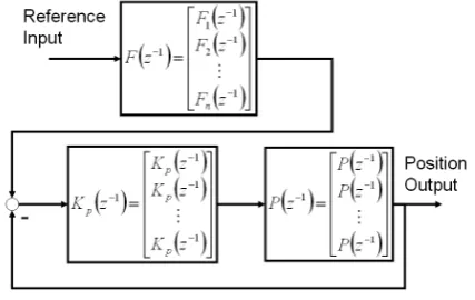
II. FEEDFORWARD MOTION CONTROL DESIGN In our study, the feedforward motion control design presented in [15] was applied to improve both the tracking accuracy and the contouring accuracy for multi-axis motion control systems as shown in Fig. 1. The position feedback transfer function that differs for each axis T zi
( )
−1 can be expressed as
( )
( ) ( )
( ) ( )
( )
( )
1( )
1 1 1 1 1 1 1 1 1 − − − − − − − − − ⋅ ⋅ = ⋅ + ⋅ = z A z B z B z z P z K z P z K z T p i pu i pa i i pi i pi
i (1)
where Bi
( )
zpa −1 denotes the polynomials with acceptable zeros such as stable zeros; Bi
( )
z [image:2.595.321.535.127.262.2]pu −1 denotes the polynomials with unacceptable zeros such as unstable and nearly unstable zeros.
Fig. 1. Two-degrees-of-freedom motion control systems.
Based on the design of the optimal ZPETC [5] and complementary zeros, the feedforward controller F zi
( )
−1 is designed as
( )
( )
( )
( )
( )
F z DPF z z A z
B z B z
i i i p i pa j pu j j i n − − − − − = ≠ = ⋅ ⋅ ⋅
∏
1 1 1 1 1 1 (2)The corresponding axial transfer function R zi
( )
−1 for each axis is then obtained as
( )
( ) ( )
( )
( )
R zi F zi T zi DPF zi Bjpu z
j n − − − − − = = ⋅ = ⋅
∏
1 1 1 1 1
1
(3) To achieve identical axial transfer functions for all axes, the feedforward controller F zi
( )
−1 can be designed as
( )
( )
( )
( )
( )
F z DPF z z A z
B z B z
i i p i pa j pu j j i n − − − − − = ≠ = ⋅ ⋅ ⋅
∏
1 1 1 1 1 1 (4) where,DPF z( ) DPFM(z ) DPF zP( )
− − −
= ⋅
1 1 1 (5)
DPFM z k z z
k k k N P ( −) ( − ) = − =
∑
⋅ + 1 0 α (6)DPF z B z B P u u ( ) ( ) ( ) − = 1 2 1 (7)
[
]
TP N P N T T T T A A A A A ] 1 ) 1 [( 1 0 1 1 2 1 1 2 1 1 1 × + − − − − − = − + = α α α β β β γ β γ α L (8)
[
]
β= 2 2 2 − + × 1 1
L
[(N P ) ]
T
(9)
[
]
γ = γ γ0 1LγP P+ ×1 1 T
[( ) ] (10)
A AT TAd 1 1 2 1 2 =
∫
πθ γγ θ
θ
(12)
A2 Ad
1 2 1
2
=
∫
πθ θ
θ
(13)
N: the order of digital pre-filter DPF z( −1).
P: the number of unacceptable zeros.
Then, by substituting (5)-(13) into (3), the control system transfer function R z( −1) becomes
+ ⋅ ⋅ + ⋅ = ⋅ + ⋅ = ⋅ =
∑
∑
∑
= − − = − − − = − − − − P i i i i P N k k k k u u u P N k k k k u z z z z B z B z B z z z B z DPF z R 0 0 2 1 0 1 1 1 ) ( ) ( ) 1 ( ) ( ) ( ) ( ) ( ) ( ) ( γ α α (14)where γi is the coefficient of the polynomial B z B z
B u u u ( ) ( ) ( ) − 1 2 1 corresponding to the order zi
.
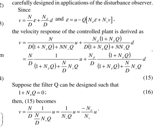
III. DIGITAL DISTURBANCE OBSERVER DESIGN Fig. 2 shows the control system based on the proposed digital disturbance observer in the discrete time domain. The proposed disturbance observer contains three parts including the input finite impulse response (FIR) filters ( −1)
z Nε and
N zv( −1) and the output filter Q z( −1). The design goal of the digital disturbance observer is to find suitable FIR filters
Nε(z−1) and N z
v( )
−1 such that the entire system can be properly represented as the nominal plant even under perturbations from external disturbances and model uncertainties.
u
+v
-d
+ +ξ
v + + + +Q z
(
−1)
1
1D z
(
−)
N z
(
−1)
N
d(
z
−1)
N
ε(
z
−)
1N
v(
z
−1)
$
d
$
δ
[image:3.595.284.552.52.272.2]ε
Fig. 2. Structure of the control system with the proposed digital disturbance observer.
Consider the system as shown in Fig. 2, where u, ε, and v
denote the reference input, driving force, and velocity output of the controlled plant, respectively. d and d$ are the external disturbance and estimated disturbance, respectively.
$
δ is the feedback signal, and ξv is the measured noise.
N z( −1) and D z( −1) are the numerator and denominator of the controlled plant, respectively. Nd(z )
−1 is the structure of the external disturbance, and Nε(z−1) and N z
v( )
−1 are the input FIR filters. Q z( −1) denotes the observer filter that must be
carefully designed in applications of the disturbance observer. Since v N D N D d d
= ε+ and ε= −u Q N
[
εε+N vv]
,the velocity response of the controlled plant is derived as
(
)
(
)
(
)
(
)
(
)
(
)
d Q N D N Q N Q N D N u Q N D N Q N D N d Q NN Q N D Q N N u Q NN Q N D N v v d v v d v + + + + + + = + + + + + + = ε ε ε ε ε ε 1 1 1 1 1 1 1 . (15) Suppose the filter Q can be designed such that1+N Qε =0; (16)
then, (15) becomes
v N D N
DN Q u
N Qu N N u
v v v
= 1 = 1 =− ε .
By setting the velocity transfer function as the nominal plant, i.e., v u N N N D v n n
=− ε = ,
the input FIR filters Nε(z )
−1 and N z
v( )
−1 are designed as
Nε(z ) Nn(z )
− −
= −
1 1 and N z D z
v( ) n( )
− −
=
1 1 .
The assumption of (16) becomes
N zn( ) (Q z )
− −
=
1 1
1 (17)
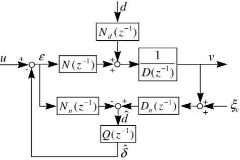
The structure of the digital disturbance observer is then obtained as shown in Fig. 3. All the sub-systems in the digital disturbance observer are stable, and the nominal plant
P z N z D z n v n n ( ) ( ) ( ) − − − = 1 1
1 can be an arbitrary stable system with unstable numerators. By considering the measurement noise
ξv, the velocity response of the proposed digital disturbance
observer is derived as
(
)
(
)
(
)
(
)
(
)
(
)
(
)
(
n)
n vn n n n d n n v n n n n n n d n n Q D D N Q N Q D D N d Q D D N Q N Q N D N u Q D D N Q N D N Q ND Q N D NQD d Q ND Q N D Q N N u Q ND Q N D N v ξ ξ + − − + − − + + − = + − − + − − + + − = 1 1 1 1 1 1 1 1 1
If the filter Q is designed such that
N zn( ) (Q z )
− − = 1 1 1, then v N D u n n v
= −ξ .
However, if the filter Q is designed such that
N zn( ) (Q z )
− −
=
1 1 0 ,
[image:3.595.48.286.462.621.2]Therefore, the filter Q must be designed such that
1 1
1 1
( ) ( ) 1, in the lower-frequency region ( ) ( ) 0, in the higher-frequency region
n n
N z Q z N z Q z
− −
− −
=
=
(18) to reduce the effect of external disturbances and to eliminate measurement noise.
u
+v
-d
+ +
ξ
v+ + - +
Q z
(
−1)
1
1D z
(
−)
N z
(
−1)
N
d(
z
−1)
N
n(
z
−1)
D z
n(
−1)
$
d
$
δ
[image:4.595.50.288.131.290.2]ε
Fig. 3. Structure of the digital disturbance observer.
Since the design of the filter Q closely relates to the nominal numerator N zn( −1), the design of Q has three steps. First, stable pole-zero cancellations are directly employed. Second, an all-pass filter is employed to re-shape the frequency response. Then, the low-pass filter is embedded to achieve the frequency response as in (18). The nominal numerator N zn( −1)is separated as
N zn Nna z N z
n u
( −1)= ( −1) ( −1) where Nn z
a
( −1) denotes the acceptable polynomial with stable roots and Nnu(z−1) denotes the unacceptable polynomial with unstable and nearly unstable roots. Suppose the unacceptable polynomial Nnu(z−1) is represented as
(
)
) ( ˆ
) (
2 2 1 1
2 2 1 1 1
z N z
b z
b z b z
z b z b z b z N
u n m
m m
m m
m m u
n
⋅ =
+ +
=
+ + =
−
− −
−
− −
− −
L L
;
then, we design the filter Q as
[
]
Q z
N z N z
LPF z
n a
n u
( )
( ) $ ( )
( ) *
−
−
− =
⋅
⋅ 1
1
1
1 (19)
where
[ ]
•* denotes the complex conjugate operator and[
$ ( )]
*(
( ) ( ))
Nnu z b z m b z m b
m
= − − + − − + 1
1 2
2 L (20)
Note that (20) is stable and realizable, and
[
]
N z N z
n u
n u
( ) $ ( )* −1
forms a
stable all-pass filter. The low-pass filter LPF z( −1) is designed such that
[
]
Q z N z N z N z
LPF z
n
n u
n u
( ) ( ) ( )
$ ( )* ( )
− −
−
−
⋅ = ⋅
1 1
1
1
performs the desired frequency response as in (18).
The stability of the digital disturbance observer, as shown in Fig. 3, can be demonstrated as follows. Define the equivalent plant R as
R D N D N
n n
= ⋅ −
and the equivalent feedback system S as shown in Fig. 4. Then, since
(a) the system S is internally stable, implying that Q z( −1),
R z( −1), and 1 1+ −1 −1
Q z( ) (R z )
are all stable;
(b) all subsystems of digital disturbance observer,
N N
D N D Q
d, , , n, n,
1
, are stable; and
(c) the transfer function 1 1+ −1 −1
Q z( ) (R z )
dominates the characteristic roots of the digital disturbance observer system,
then the digital disturbance observer in Fig. 3 is internally stable if the equivalent feedback system S is internally stable. According to the stability analysis, the filter Q z( −1) closely relates to system stability, and the low-pass filter LPF z( −1) in filter Q z( −1) is then designed to achieve the desired stability and the desired frequency response. The trade-off condition between stability and desired frequency response generally exists in the LPF z( −1) design.
+
-
Q z
(
)
R z
(
)
−1 −1
[image:4.595.312.542.333.403.2]Fig. 4. Equivalent feedback loop system S.
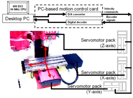
IV. EXPERIMENTAL RESULTS
The experimental setup of a DYNA 1007 3-axis CNC milling machine is shown in Fig. 5. A PC-486 generated the main control commands and recorded the principal signals including the input command calculation for different contours, the implementation of controller, and the control inputs to the velocity loop. The machine feed system was driven by SEM AC servomotor packs. The PC-486 interface utilized a PC-based motion control card with D/A converters and digital decoders to send and receive the control inputs and position outputs, respectively, in a sampling period of 1 ms. The velocity loops of a real biaxial motion system are obtained by applying the identification algorithm [20] as
( )
V z z z z
z z z
x
−
− − −
− − −
= 1
1 2 3
1 2 3
- 0.00437948 + 0.04225802 + 0.09618655 1- 0.88944678 + 0.23980063 - 0.19529895
( )
V z z z z
z z z
y
− − − −
− − −
= 1
1 2 3
1 2 3
- 0.00141126 + 0.04402946 + 0.09340968 1- 0.83356582 - 0.04295967 + 0.03239339 To illustrate the performance of the proposed feedforward motion control in industrial applications, circular motion tests with different speed commands, 5000.0 mm/min and 600.0 mm/min, were applied to control the motion of the CNC milling machine. Moreover, results of three control designs were compared as follows:
Case (A): The conventional approach in which the position controllers were designed to achieve a 0.707 damping ratio for each axis and constant gain matched dynamics at zero-frequency response among all motion axes.
disturbance observer design. The nominal plant of the digital disturbance observer was set such that it was identical to the model of the velocity loop. The observer filter was designed according to the developed procedures as
Q z
z z
z z z
z z
z z z
z z
x( )
−
− −
− − −
− −
− − −
− −
= 1
1 2
3 4 5
1 2
3 4 5
6 7
0.00497194 + 0.024859747 + 0.04971949
+ 0.04971949 + 0.02485974 + 0.00497194 1 - 2.94719898 + 3.23989221
- 1.20983151 - 0.4541163 + 0.52748002
- 0.14373367 + 0.00883831
Q z
z z
z z z
z z
z z z
z z
y( )
−
− −
− − −
− −
− − −
− −
= 1
1 2
3 4 5
1 2
3 4 5
6 7
0.00511975 + 0.02559877 + 0.05119755
+ 0.05119755 + 0.02559877 + 0.00511975 1- 2.91517429 + 3.16186245
- 1.1599981 - 0.41974012 + 0.46329684
- 0.11089379 + 0.00293275
Case (C): Based on the motion control design in Case (B), the motion control system also used the proposed feedforward motion control design as
Fx=
0.01723z - 0.12414z + 0.43087z - 0.92338z
+ 1.23579z - 0.71192z - 0.9653z + 1.2187z
+ 0.28642z - 0.52494z + 0.1532z - 0.10311
- 0.03728z + 0.06244z - 0.03431z + 0.01035z
+ 0.00058z - 0.00296z + 0.00154z - 0.00028z
+ 0.00002z - 0.0000004z 1
11 10 9 8
7 6 5 4
3 2 1
-1 -2 -3 -4
-5 -6 -7 -8
-9 -10
Fy =
0.0455z - 0.33378z + 1.17667z - 2.56202z
+ 3.50475z - 2.15621z - 2.49663z + 3.69766z
+ 0.30195z - 1.20246z + 0.1698z - 0.49712
+ 0.24032z + 0.22289z - 0.23889z + 0.11762z
- 0.01866z - 0.01755z + 0.01362z - 0.00372z
+ 0.00032z - 0.0000068z
1 + 0.59884556879887z
11 10 9 8
7 6 5 4
3 2 1
-1 -2 -3 -4
-5 -6 -7 -8
-9 -10
-1
Results of the circular motion tests are summarized in Table I and Fig. 6. Note that the contouring errors shown in Fig. 6 are amplified 100 times. Clearly, the proposed feedforward motion control design significantly improved both the tracking accuracy and contouring accuracy of the applied CNC milling machine. To increase the bandwidth of servo systems, we developed a feedforward motion control design by developing a zero-phase digital pre-filter design and a phase compensation algorithm. Experimental results indicate that the proposed feedforward motion control design significantly improved the tracking accuracy of servo systems. We designed the feedforward motion control for multiple axes to achieve identical dynamic properties among all axes with zero-phase lag error. By using the proposed feedforward control design, tracking and contouring accuracy were both significantly improved in multi-axis motion systems. Because the proposed feedforward motion control design is a model-based approach, a digital disturbance observer was
[image:5.595.308.539.140.310.2]integrated with the motion control design in order to reduce adverse effects induced by model uncertainties and external disturbances. In motion systems with serious nonlinearity, which give rise to friction, the slip-stick phenomenon can be further reduced if the motion controller is designed to compensate for friction [21, 22].
Fig. 5. Experimental setup.
TABLEI
EXPERIMENTAL RESULTS OF THE CIRCULAR MOTION TESTS WITH DIFFERENT
CONTROL DESIGN AND SPEED COMMANDS
Controller Performance
Case (A) Case (B) Case (C) Speed command of 5000.0 mm/min
Contouring error (RMS, mm)
0.0242 0.0145 0.0041 Tracking error
(RMS, mm)
1.2028 1.1750 0.0052 Speed command of 600.0 mm/min
Contouring error (RMS, mm)
0.0321 0.0016 0.0016 Tracking error
(RMS, mm)
0.2046 0.1521 0.0019
V. CONCLUSION
Feedforward motion control is conventionally designed individually for improving the tracking accuracy of motion control systems used in CNC machine tools. However, the individual design of feedforward motion control usually leads to mismatched dynamics among all synchronized motion axes and may seriously degrade contouring accuracy, particularly under high-speed machining processes. Therefore, we developed the feedforward motion control design presented in this paper for improving both the tracking and contouring accuracy of motion control systems in CNC machine tools. By applying stable pole-zero cancellation to individual axes and by employing complementary zeros for all uncancelled zeros, the feedforward motion control design led to matched dynamics among all motion axes and thereby achieved highly accurate contouring and tracking results.
In motion control systems, the model-based control design is usually sensitive to external disturbances and plant uncertainties. We thus developed a digital disturbance observer design to significantly reduce those adverse effects, and as a result, our feedforward motion control design achieved high-precision motion accuracy and good motion robustness in real applications. A systematic design procedure was developed, including stable pole-zero cancellation, all-pass filter design, and low-pass filter design, so that the digital disturbance observer became more feasible for the feedforward motion control design. An internal stability criterion was further employed to validate stability in application of the developed digital disturbance observer to show that it maintained system stability and provided good execution performance. Finally, experimental results performed on a 3-axis CNC milling machine show that our feedforward motion control design and digital disturbance observer design are feasible and can significantly improve both tracking accuracy and contouring accuracy; thus, they provide high-precision motion in CNC machine tools.
REFERENCES
[1] A. Poo, J. G. Bollinger, and W. Younkin, “Dynamic Error in Type Contouring Systems,” IEEE Transactions on Industry Application, vol. IA-8, no. 4, pp. 477-484, 1972.
[2] M. Tomizuka, “Zero Phase Error Tracking Algorithm for Digital Control,” ASME Transactions on Journal of Dynamic System, Measurement and Control, vol. 109, pp. 65-68, 1987.
[3] T. C. Tsao and M. Tomizuka, “Robust Adaptive and Repetitive Digital Tracking Control and Application to A Hydraulic Servo for noncircular Machining,” ASMETransactions on Journal of Dynamic System, Measurement and Control, vol. 116, pp. 24-32, 1994. [4] J. Z. Xia and C. H. Menq, “Precision Tracking Control of
Nonminimum Phase Systems with Zero Phase Error,” International Journal of Control, vol. 61, no. 4, pp. 791-807, 1995.
[5] S. S. Yeh and P. L. Hsu, “An Optimal and Adaptive Design of the Feedforward Motion Controller,” IEEE/ASME Transactions on Mechatronics, vol. 4, no. 4, pp. 428-439, 1999.
[6] Y. Koren, “Cross-Coupled Biaxial Computer for Manufacturing Systems,” ASME Transactions on Journal of Dynamic System, Measurement and Control, vol. 102, no. 4, pp. 265-272, 1980. [7] P. K. Kulkarni and K. Srinivasan, “Optimal Contouring Control of
Multiaxis Drive Servomechanisms,” ASMETransactions on Journal of Dynamic System, Measurement and Control, vol. 111, no. 2, pp. 140-148, 1989.
[8] P. K. Kulkarni and K. Srinivasan, “Cross-Coupled Control of Biaxial Feed Drive Servomechaniasms,” ASMETransactions on Journal of Dynamic System, Measurement and Control, vol. 112, no. 2, pp. 225-232, 1990.
[9] H. Y. Chuang and C. H. Liu, “Cross-Coupled Adaptive Feedrate Control for Multiaxis Machine Tools,” ASMETransactions on Journal of Dynamic System, Measurement and Control, vol. 113, no. 3, pp. 451-457, 1991.
[10] H. Y. Chuang and C. H. Liu, “A model Reference Adaptive Control Strategy for Improving Contour Accuracy of Multiaxis Machine Tools,” IEEE Transactions on Industry Application, vol. 28, no. 1, pp. 221-227, 1992.
[11] S. Jee and Y. Koren, “A self-organizing fuzzy logic control for Friction Compensation in Feed Drives,” IEEE Proceedings ACC., pp. 205-209, 1995.
[12] C. C. Lo, “Three-Axis Contouring Control Based on a Trajectory Coordinate Basis,” JSME International Journal Series C-Mechanical Systems Machine Elements & Manufacturing, vol. 41, no. 2, pp. 242-247, 1998.
[13] G. T. C. Chiu and M. Tomizuka, “Contouring Control of Machine Tool Feed Drive Systems: A Task Coordinate Frame Approach,” ASME Dynamic Systems and Control Division, vol. 57-1, pp. 503-510, 1995. [14] S. S. Yeh, Z. H. Tsai, and P. L. Hsu, “Applications of Integrated Motion Controllers for Precise CNC Machines,” International Journal of Advanced Manufacturing Technology, vol. 44, no. 9-10, pp. 906-920, 2009.
[15] S. S. Yeh and J. T. Sun, “Design of perfectly matched zero-phase error tracking control for multi-axis motion control systems,” Proceedings of SICE Annual Conference, pp. 528-533, 2012.
[16] S. Endo, M. Tomizuka, and Y. Hori, “Robust digital tracking controller design for high-speed positioning systems,” IEEE Proceedings ACC., vol. 3, pp. 2494-2498, 1993.
[17] H. S. Lee and M. Tomizuka, “Robust Motion Controller Design for High-Accuracy Positioning Systems,” IEEE Transactions on Industrial Electronics, vol. 43, no. 1, pp. 48-55, 1996.
[18] C. J. Kempf and S. Kobayashi, “Disturbance observer and feedforward design for a high-speed direct-drive positioning table,” IEEE Transactions on Control System Technology, vol. 7, no. 5, pp. 513-526, 1999.
[19] M. Bertoluzzo, G. S. Buja, and E. Stampacchia, “Performance analysis of a high-bandwidth torque disturbance compensator,” IEEE/ASME Transactions on Mechatronics, vol. 9, no. 4, pp. 653-660, 2004. [20] T. Söderström and P. Stoica, System Identification. New York:
Prentice Hall, 1989.
[21] S. S. Yeh and H. C. Su, “Development of Friction Identification Methods for Feed Drives of CNC Machine Tools,” International Journal of Advanced Manufacturing Technology, vol. 52, no. 1-4, pp. 263-278, 2011.