Abstract—Incorrect angular placement of the acetabular cup in total hip replacement induces femoral head dislocation, osteolysis, and liner wearing. Some computer-assisted navigation systems to aid acetabular cup placement have been developed in the past decade, but these are not used extensively due to their expense. In this study, a novel algorithm to determine the positions of data points in three-dimensional space from a single-plane image was developed. Based on the validation outcomes, the errors between the true coordinates and the computed coordinates were less than 0.1%. This algorithm was employed in the development of an intrasurgical cup navigation system, which we called the CupNav system. The CupNav system consists of four main hardware components: one digital camera, one laptop, one movable trolley cart, and two self-developed assistant guide frames. In-vitro laboratory validation tests indicated that the possible orientation errors induced by the prototype of CupNav system were less than 1.9 degrees in abduction and 1.4 degrees in anteversion. Although the CupNav system for acetabular cup placement is in the early phase of development, it is clear that the minimal hardware requirement (and hence low cost) of this navigation system makes it suitable for the widespread training and evaluation of inexperienced doctors.
Index Terms—navigation, acetabular cup, computed
tomography free; computer-assisted surgery, single image
I. INTRODUCTION
One of the early postoperative complications following total hip replacement (THR) is the dislocation of the femoral head from the acetabular component [1,2]. Most of the time, this is owing to the incorrect angular placement of the acetabular cup. In addition to the femoral head dislocation, incorrect orientation of the cup might also cause implant impingement, pelvic osteolysis, acetabular migration, as well as liner wearing [3,4]. Generally, the optimal orientation of
Manuscript received February 24, 2011; revised March 01, 2011. All of the authors have no financial relationship to any private companies and organizations.
Jui-Ting Hsu is with the School of Dentistry, China Medical University, No.91 Hsueh-Shih Road, Taichung 404, Taiwan
Chih-Han Chang is with the Institute of Biomedical Engineering, National Cheng Kung University, No. 1 University Road, Tainan 701, Taiwan
Heng-Li Huang is with the School of Dentistry, China Medical University, No.91 Hsueh-Shih Road, Taichung 404, Taiwan
Ming-Tzu Tsai is with the Department of Biomedical Engineering, HungKuang University, No.34 Chung-Chie Road, Sha Lu, Taichung 443, Taiwan.
Kuo-An Lai is with the Orthopaedic Department, National Cheng Kung University Medical Center, No.138 Sheng Li Road, Tainan 701, Taiwan
(corresponding author: Jui-Ting Hsu. phone: +886-928-174142; fax: +886-4-22014043; e-mail: [email protected]).
the acetabular component is for it to be inserted into the acetabulum with an abduction angle of 4010 degrees (meanrange) and an anteversion angle of 1510 degrees [5]. However, optimal acetabular cup placement continues to be a surgical challenge in THR, especially for the less-experienced surgeon. Mechanical devices are available in guiding the cup placement during surgery. Nevertheless, these devices assumed that the trunk and pelvis of the patient are aligned in a known orientation relative to the operating table, and do not take into account individual variations in a patient’s anatomy or the actual position of the pelvis [6]. Using only these acetabular guides for intraoperative alignment could lead to wide deviation between the desired and actual orientation. This has lead to a variety of computer-assisted surgery technologies being introduced for THR over the past decade.
Computer-assisted navigation systems for acetabular cup placement can be categorized as computed tomography (CT) based and CT free. In CT-based navigation systems [3,7-9], preoperative CT scanning is used to establish the pelvic computer model that the surgeon uses in three-dimensional (3D) preoperative planning as well as in determining the cup orientation during surgery based on the intraoperative registration between the virtual model and the actual pelvic orientation. One of the CT-based navigation systems is called the HipNav system [3,6-8,10,11], which although demonstrating favorable results is also associated with some drawbacks, such as the need for the additional CT images [12], which results in extra costs and additional radiation exposure for the patient, and the need for detailed preoperative planning [13]. One example of the CT-free approach [12,14,15], is the hybrid CT-free navigation system developed by Langlotz et al. [16]. CT-free navigation systems greatly simplify the operative process and reduce the preoperative time, but the clinical application of CT-free navigation systems remains limited due to their expense. Moreover, both the CT-based and CT-free navigation systems need at least two tracking cameras, and this can hinder the surgical procedures. Therefore, reducing the preoperative time, the required hardware components, and the cost would increase the popularity of computer-assisted navigation surgery.
In this study, we developed a single-image-based navigation system for acetabular cup placement. This system requires only a single planar image (and hence only one camera) to determine the coordinates of spatial points, thus minimizing the hardware requirements during surgery.
Computer-Assisted Navigation for Acetabular
Cup Placement: a Single Image Guiding System
II. SINGLE-IMAGE-BASED ALGORITHM
Before presenting the cup navigation system, it is necessary to introduce the single-image-based algorithm in determining the coordinate positions of target points in 3D space.
The general scheme of transferring an image point into 3D space (i.e., back-projection) involves connecting the projected point on the image to the focus point, thus reconstructing the projection line of the spatial point. When at least two images of the same point taken from different positions are available, two projection lines can be established and the intersection of these two projection lines is regarded as the position of the targeted point. The disadvantages of this multiple-image approach are (1) two image-capture systems are required and (2) more crucially, the relative positions of the image-capture systems must be calibrated in advance so that all the projection lines can be constructed within the same coordinate system. In this study we proposed a single-image-based algorithm for determining the coordinates of spatial points with minimal set-up requirements.
Formulation:
The general idea of the algorithm is described below: For a single spatial target point projected on an image plane, two linear equations can be established for the projection line in 3D space. However, the spatial target point needs three equations to determine its three coordinates. Employing a second spatial point at a known distance from the first target point generates six coordinate unknowns but five equations (four from the two projection lines of the two points and one from known distance between these two points). With three spatial points, the distance between each point-pair is provided, nine coordinate unknowns and nine equations could be established, and thus the spatial locations of these three points can be determined.
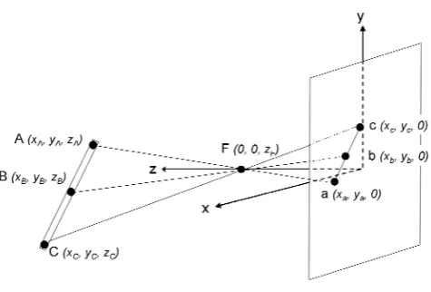
For computational simplicity, the three points are arranged to be collinear, with the middle point located at the center of the other two points, in this study. To illustrate the nine equations, the pinhole image-capture model as shown in Fig. 1 is referred. In the figure, the spatial points A, B, and C are the target points with unknown coordinates (three for each point), and point F is the focus point. On the image plane, points a, b, and c are the image points projected from points A, B, and C, respectively. The coordinates of F is set as
)
(
0,0,
z
F and the coordinates of points a, b, and c are represented as(
,
,
)
0
a a
y
x
,(
,
,
)
0
b b
y
x
, and(
,
,
)
0
c c
y
x
, [image:2.595.307.545.62.223.2]respectively; that is, the coordinate system is selected as the xy plane located on the image plane and the z axis passing through the focus point.
Fig. 1. The pinhole image-capture model. Points A, B, and C are the three collinear target points in 3D space, with point B located at the center of points A and C. Points a, b, and c are the corresponding projected image points located on the xy (image) plane, while point F is the focus point located on the z axis.
Firstly, the location of point B at the center of line AC yields the following three linear equations:
2 2 2 C A B C A B C A B z z z y y y x x
x
For each projection line, the following two linear equations can be obtained:
F a F A F a F A F a F A F a F A z z z z x x x x y y y y x x x x
(projection line
AFa, with
x
F
y
F
0
)However, since points A, B, and C are collinear, the six equations from the three projection lines have a rank of only five; i.e., there are only five independent linear equations. Finally, the length of line AC (LAC, a known value) is described by AC C A C A C
A x y y z z L
x )2( )2( )2 (
Because this length equation is nonlinear, two solutions are available. However, one of the solutions is clearly incorrect, being located behind the image plane (i.e., with negative z coordinates), and hence can be readily excluded. In total there are nine equations that could uniquely determine the nine unknown coordinates of points A, B, and C.
Implementation:
The difference between the obtained distance and the target LAC is set as the objective function:
2 2 2
2 ( ) ( ) )
) ( ( )
(zB xA xC yA yC zA zC LAC
f
Each iteration of the optimization loop involves updating the value of
z
B so as to reduce the value of the objective function. The entire procedure was implemented in MATLAB 5.3 (MathWorks, Natick, MA, USA) using the built-in function fminsearch as the optimization engine. Program Validation:Three virtual data sets were set up to validate the implemented program. In each data set, the coordinates of the three target points (A, B, and C) were predetermined with LAC equals to 100 mm. These target points were projected to the xy (image) plane with the focus point located at
mm 20.7 F
z . The projected coordinates of points a, b, and c along with
z
F were then used as the input data to theoptimization program and the output coordinates of points A, B and C were compared with the real coordinates of these three points. To test the effective range of this program, the
B
z
values in the three test sets were selected as 150 mm, 1500 mm, and 15000 mm. The results showed that the normalized errors between the true coordinates and the computed coordinates of the three target points in three test sets were all less than 0.1%. The time required to obtain the solutions of each set was less than 1 second using Pentium 1.6 GHz with convergent tolerance set at10 -9.III. DEVELOPMENT AND VALIDATION OF THE CUP NAVIGATION SYSTEM
sing the single-image-based algorithm, an intrasurgical cup navigation system was developed: we called this the CupNav system. In section 3.1–3.3, the hardware and software, surgical procedure, and validation of the system, were described respectively.
Hardware and Software
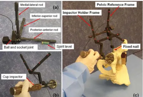
[image:3.595.305.548.49.213.2]The CupNav system consists of four main components: (i) one Canon PowerShot G3 digital camera; (ii) one IBM T42 laptop; (iii) one movable trolley cart, and (iv) two self-developed assistant guide frames (Fig. 2). The digital camera, controlled by the laptop via Universal Serial Bus connection, is used to track the orientation of the two guide frames through the light emitting diodes (LEDs) embedded on the frames. The camera and laptop are fixed on a movable trolley cart. The two guide frames are used as: (i) the pelvic reference frame (PRF) fixed on the pelvis in order to setup the reference coordinate system of pelvis during surgery (Fig. 2a), and (ii) the cup impactor holder frame (IHF) fixed on the cup impactor to determine the cup orientation prior to impact (Fig. 2b).
Fig. 2. Photographs showing the two self-developed guide frames: (a) the pelvic reference frame (PRF), (b) the impactor holder frame (IHF), and (c) using the CupNav system with the equipped tools.
The upper part of the PRF consists of three rods perpendicular with each other to represent the three axes of the pelvic frame (z-axis by the inferior-superior rod, y-axis by the medial-lateral rod, and x-axis by the posterior-anterior rod). Three red LEDs 5 cm apart, are embedded in each of the three rods and are used as the three collinear points (points A, B, and C, in Fig. 1.) in the single-image-based measuring algorithm. The lower part of the PRF consists of a ball-and-socket joint (Fig. 2a) for adjusting the three-axis rods aligned with the pelvis orientation (the adjusting procedure is described in Section 3.2). The inferior-superior and posterior-anterior rods also contain a small spirit level (Fig. 2a) in helping the adjustment.
The IHF is a two-rod frame (Fig. 2b) and, similar to the PRF, three LEDs are embedded in each rod and used as the three collinear points for the single-image-based measuring algorithm. This IHF is mounted on the impactor and the plane constructed by the two-rod fame is perpendicular to the long axis of the impactor. The orientation of the impactor during surgery could thus be determined by the cross-product of the two-rod directions. The purpose of using a two-rod design instead of a one-rod frame mounted along the axial direction of the impactor is to prevent the possible obscure of the IHF during surgery.
Fig. 3 The software interface of the CupNav system is showed. The Reference button calculates the coordinate system of the pelvis. The Impactor button obtains the orientation of the cup impactor. The upper two x-ray figures show the current cup angles of abduction and anteversion. The lower left graph identifies the errors in these two angles. (The green dot indicates the target orientation of the cup while the red dot is the actual cup orientation).
Fig. 4. The image-processing procedures: (a) the original color image, (b) the binary image after thresholding with the intensity of red color, (c) noises on the lower right portion would be filter out, and (d) two-dimensional centroid of a LED
Surgical Procedure
The most crucial step in applying the CupNav system is to align the PRF with the anatomic coordinate system of the pelvis. To achieve this alignment the anterior pelvis plane (APP) used in the study of Jaramaz et al. [3] is referred. The APP is defined by the two anterior superior iliac spines and the two pubic tubercles (Fig. 5). This plane defines the pelvic coordinate system from which pelvic and acetabular cup alignment are measured. Prior to the surgery, the patient is positioned and stabilized on the operating table in the lateral decubitus position, with the APP perpendicular to the operating table and the inferior-superior axis of the pelvis parallel to the operating table [6]. The PRF is then mounted on a nail fixed to the superior up of the acetabulum (Fig. 2c), and the inferior-superior and posterior-anterior rods are orientated parallel to the operating table using the spirit level. The PRF is further rotated around the medial-lateral rod until
the inferior-superior rod is parallel to the line formed by the anterior superior iliac spine and pubic tubercles. The fluoroscopy image from C-arm is employed to confirm the alignment outcome. After confirmation, the ball-and-socket joint on the PRF is locked to prevent movement between the PRF and the pelvis. This allows the movement and orientation of the pelvis to be monitored continuously throughout the surgery by calculating the position of the PRF.
[image:4.595.49.289.366.532.2]Once the PRF is aligned with the pelvis, the References button is clicked to register the PRF orientation. Then, the cup is placed in a free-hand manner, and the Impactor button is clicked to determine the relative positions between the IHF and the PRF, which yields the abduction and anteversion of current cup setup. The cup is fixed into the acetabulum if this orientation is deemed suitable for the patient. Otherwise, the cup orientation, and thus the direction of the IHF, is re-adjusted and the Impactor button is clicked again until the desired orientation is obtained. If the pelvis moves during surgery, its coordinate system must be recalculated by clicking the References button again.
Fig. 5. Definition of the pelvic coordinate system. The three axes of the anterior pelvic plane are defined using four pelvic landmarks: both anterior superior iliac spines and two pubic tubercles.
System Validation
TABLE I
Orientation of the cup determined from the 3D digitizer and the CupNav system.
Trial
number Cup orientation
BHN 710 (degrees)
CupNav (degrees)
Error (degrees)
# 1 Abduction 44.2 42.3 1.9 Anteversion 14.1 12.7 1.4
# 2 Abduction 45.9 44.1 1.8 Anteversion 35.3 34.1 1.2
Many factors would contribute the errors of current prototype of the CupNav system. However, based on the high accuracy of the virtual data test for the program, the major factors inducing the errors should from the input data of the single-image measuring algorithm no the algorithm itself. One of the errors is the centroid position of the LED determined from the imaging processing procedure. This is sourced from the scattering and uneven intensity of the LEDs. Moreover, the different orientations of the pelvis determined from the APP in the digitizer measuring and from the PRF in the CupNav system would also contribute the variations between these two approaches, in addition to the dimensions tolerances of the two hand-mad reference frames.
IV. CONCLUSIONS AND FUTURE WORKS
A novel algorithm to determine the positions of data points in 3D space from single-plane image was developed and applied to the guiding system of acetabular cup placement. The major advantage of this algorithm is that it requires little a prior information: only three collinear points separated with a known distance, which cut down the required hardware setup of a cup guiding system. In-vitro laboratory tests indicated that the possible orientation errors induced by the prototype of CupNav system are less than 1.9 degrees and could be reduced by better LED setup and more precise manufacturing of the frames. Nevertheless, the minimum hardware requirement of this CupNav system makes it possible to provide an affordable guiding system for the training and evaluation of inexperience doctors.
REFERENCES
[1] D. E. McCollum and W. J. Gray, "Dislocation after total hip arthroplasty. Causes and prevention," Clinical Orthopaedics and
Related Research, no. 261, pp. 159-170, Dec. 1990.
[2] E. Garcia-Cimbrelo and L. Munuera, "Dislocation in low-friction arthroplasty," The Journal of Arthroplasty, vol. 7, no. 2, pp. 149-155, Jun. 1992.
[3] B. Jaramaz, A. M. DiGioia, 3rd, M. Blackwell and C. Nikou, "Computer assisted measurement of cup placement in total hip replacement,"
Clinical Orthopaedics and Related Research, no. 354, pp. 70-81, Sep.
1998.
[4] T. P. Schmalzried, D. Guttmann, M. Grecula and H. C. Amstutz, "The relationship between the design, position, and articular wear of acetabular components inserted without cement and the development of pelvic osteolysis," The Journal of Bone and Joint Surgery [Am], vol. 76, no. 5, pp. 677-688, May. 1994.
[5] G. E. Lewinnek, J. L. Lewis, R. Tarr, C. L. Compere and J. R. Zimmerman, "Dislocations after total hip-replacement arthroplasties,"
The Journal of Bone and Joint Surgery [Am], vol. 60, no. 2, pp.
217-220, Mar. 1978.
[6] A. M. Digioia, 3rd, B. Jaramaz, A. Y. Plakseychuk, J. E. Moody, Jr., C. Nikou, R. S. Labarca, T. J. Levison and F. Picard, "Comparison of a mechanical acetabular alignment guide with computer placement of the socket," The Journal of Arthroplasty, vol. 17, no. 3, pp. 359-364, Apr. 2002.
[7] A. M. DiGioia, 3rd, S. Blendea and B. Jaramaz, "Computer-assisted orthopaedic surgery: minimally invasive hip and knee reconstruction,"
Orthopedic Clinics of North America, vol. 35, no. 2, pp. 183-189, Apr.
2004.
[8] A. M. DiGioia, 3rd, A. Y. Plakseychuk, T. J. Levison and B. Jaramaz, "Mini-incision technique for total hip arthroplasty with navigation," The
Journal of Arthroplasty, vol. 18, no. 2, pp. 123-128, Feb. 2003.
[9] T. Leenders, D. Vandevelde, G. Mahieu and R. Nuyts, "Reduction in variability of acetabular cup abduction using computer assisted surgery: a prospective and randomized study," Computer Aided Surgery, vol. 7, no. 2, pp. 99-106, 2002.
[10] A. M. DiGioia, 3rd, B. Jaramaz, M. Blackwell, D. A. Simon, F. Morgan, J. E. Moody, C. Nikou, B. D. Colgan, C. A. Aston, R. S. Labarca, E. Kischell and T. Kanade, "The Otto Aufranc Award. Image guided navigation system to measure intraoperatively acetabular implant alignment," Clinical Orthopaedics and Related Research, no. 355, pp. 8-22, Oct. 1998.
[11] A. M. DiGioia, 3rd, B. Jaramaz and B. D. Colgan, "Computer assisted orthopaedic surgery. Image guided and robotic assistive technologies,"
Clinical Orthopaedics and Related Research, no. 354, pp. 8-16, Sep.
1998.
[12] L. D. Dorr, Y. Hishiki, Z. Wan, D. Newton and A. Yun, "Development of imageless computer navigation for acetabular component position in total hip replacement," Iowa Orthopaedic Journal, vol. 25, no. pp. 1-9, 2005.
[13] B. M. Jolles, P. Genoud and P. Hoffmeyer, "Computer-assisted cup placement techniques in total hip arthroplasty improve accuracy of placement," Clinical Orthopaedics and Related Research, no. 426, pp. 174-179, Sep. 2004.
[14] A. Wentzensen, G. Zheng, B. Vock, U. Langlotz, J. Korber, L. P. Nolte and P. A. Grutzner, "Image-based hip navigation," IInternational
Orthopaedics, vol. 27 Suppl 1, pp. S43-46, 2003.
[15] M. Nogler, O. Kessler, A. Prassl, B. Donnelly, R. Streicher, J. B. Sledge and M. Krismer, "Reduced variability of acetabular cup positioning with use of an imageless navigation system," Clinical Orthopaedics and
Related Research, no.426, pp. 159-163, 2004.
[16] G. Zheng, A. Marx, U. Langlotz, K. H. Widmer, M. Buttaro and L. P. Nolte, "A hybrid CT-free navigation system for total hip arthroplasty,"