TEMPERATURE BASED AUTOMATIC FAN SPEED CONTROLLER
1
Nigade, A. S.,
2,*Deepanshu Verma,
1
Assistant Professor, Electronics Department, BVDU College of Engineering, Pune
2,3,4Electronics Department, BVDU College
ARTICLE INFO ABSTRACT
The research paper presented here is based on automatic fan speed controller that automatically adjusts the fan's speed according to ambient temperature of the surroundings. The temperature flow controlled fan is an automated fan, controlled by a temperature sensor, using fully hardware design. The heart of this project consists of the temperature sensor circuit which senses the change in the ambient
the signal sensed by the temperature sensor is very weak in amplitude and strength. Therefore we use amplifier to increase the strength of the signal so that the signal is able to drive the output section, in this case a fan. Here pulse width
When heat is applied to the temperature sensor, this will determine the fan automatically increasing or decreasing in speed according to the four speed levels of a normal fan that are set to differe
where the fan speed needs to increase if here dissipation increases.
Copyright © 2016, Nigade et al. This is an open access article distributed under the Creative Commons Att distribution, and reproduction in any medium, provided the original work is properly cited.
INTRODUCTION
Electric Fan (Mithal, 1992) is a very simple device that consists of rotating blades used to move air in the room. As compared to A.C., fan doesn’t change the temperature of air they only move it.It is a non-linear system, as we are considering to rotate it according to the environment temperature. We have tried to make a fuzzy inference system that has been used without any failure in establishing the relation between environment temperature and fan speed. Due to the shortage of electricity supply, we have to start research in areas energy can be used efficiently. In households during summer, A.C. is responsible for 60-70% of our summer electricity bill. The window A.C. that has been mostly employed uses 500 to 1440 watts. In comparison, an electric fan uses only 90 watts, depending upon the speed and size. Electric fan is a device that helps us to stay cool in summer while saving our money as well as protecting the environment by limiting the release of Carbon-di-oxide.
*Corresponding author: Deepanshu Verma,
Electronics Department, BVDU College of Engineering, Pune road, Pune-411043
ISSN: 0975-833X
Article History:
Received 23rd January, 2016 Received in revised form 17th February, 2016
Accepted 20th March, 2016
Published online 26th April,2016
Key words:
Automatic Fan Controller, Temperature Controlled, Power Devices Harmonics, Precision,
Pulse Width Modulation.
Citation: Nigade, A.S., Deepanshu Verma, Brajesh Kumar Pandey, and Pranjal Srivastav
International Journal of Current Research, 8, (04), 29436
RESEARCH ARTICLE
TEMPERATURE BASED AUTOMATIC FAN SPEED CONTROLLER
Deepanshu Verma,
3Brajesh Kumar Pandey and
4Pranjal
, Electronics Department, BVDU College of Engineering, Pune-Satara road, Pune
Electronics Department, BVDU College of
Engineering, Pune-Satara road, Pune
ABSTRACT
The research paper presented here is based on automatic fan speed controller that automatically adjusts the fan's speed according to ambient temperature of the surroundings. The temperature flow controlled fan is an automated fan, controlled by a temperature sensor, using fully hardware design. The heart of this project consists of the temperature sensor circuit which senses the change in the ambient temperature of the surrou
the signal sensed by the temperature sensor is very weak in amplitude and strength. Therefore we use amplifier to increase the strength of the signal so that the signal is able to drive the output section, in this case a fan. Here pulse width
When heat is applied to the temperature sensor, this will determine the fan automatically increasing or decreasing in speed according to the four speed levels of a normal fan that are set to different temperature ranges of a room. It can be used in cooling electronics devices, where the fan speed needs to increase if here dissipation increases.
is an open access article distributed under the Creative Commons Attribution License, which distribution, and reproduction in any medium, provided the original work is properly cited.
is a very simple device that consists of rotating blades used to move air in the room. As compared to A.C., fan doesn’t change the temperature of air they only linear system, as we are considering to ent temperature. We have tried to make a fuzzy inference system that has been used without any failure in establishing the relation between environment temperature and fan speed. Due to the shortage of electricity supply, we have to start research in areas where energy can be used efficiently. In households during summer, 70% of our summer electricity bill. The window A.C. that has been mostly employed uses 500 to 1440 watts. In comparison, an electric fan uses only 90 watts, nding upon the speed and size. Electric fan is a device that helps us to stay cool in summer while saving our money as well as protecting the environment by limiting the release of
epartment, BVDU College of Engineering, Pune-Satara
Problem Statement
The main idea of this project is to replace manual settings of fan in with change in temperature so that it detects temperature variations automatically and control its speed. Thus the main requirements boil down to
The temperature of the room should be temperature sensor,
The variation in temperature is further processed through the amplifier to increase the strength of the signal, and,
The signal obtained from the amplifier is given as output which is in this case is a Fan
Design Overview
In this design, the temperature sensor used here is a LM35 (http://www.ti.com/lit/ds/symlink/lm35.pdf
change in temperature and its output is provided to an amplifier which amplifies its signal so that the signal is able to drive the output. This project mainly controls the speed of fan according to the inner environment of box temperature. The temperature sensor (LM35) sensor has a temperature range from -55°C to +150°C. This control circuit control the fan speed according to signal comes from the LM 35.
Available online at http://www.journalcra.com
International Journal of Current Research
Vol. 8, Issue, 04, pp.29436-29440, April, 2016
INTERNATIONAL
Nigade, A.S., Deepanshu Verma, Brajesh Kumar Pandey, and Pranjal Srivastav, 2016. “Temperature based automatic fan speed
29436-29440.
z
TEMPERATURE BASED AUTOMATIC FAN SPEED CONTROLLER
Pranjal Srivastav
Satara road, Pune-411043
Satara road, Pune-411043
The research paper presented here is based on automatic fan speed controller that automatically adjusts the fan's speed according to ambient temperature of the surroundings. The temperature flow controlled fan is an automated fan, controlled by a temperature sensor, using fully hardware design. The heart of this project consists of the temperature temperature of the surroundings. As the signal sensed by the temperature sensor is very weak in amplitude and strength. Therefore we use amplifier to increase the strength of the signal so that the signal is able to drive the output section, in this case a fan. Here pulse width modulation is use in this case. When heat is applied to the temperature sensor, this will determine the fan automatically increasing or decreasing in speed according to the four speed levels of a normal fan that are It can be used in cooling electronics devices, where the fan speed needs to increase if here dissipation increases.
ribution License, which permits unrestricted use,
The main idea of this project is to replace manual settings of fan in with change in temperature so that it detects temperature variations automatically and control its speed. Thus the main
The temperature of the room should be determined by the
The variation in temperature is further processed through the amplifier to increase the strength of the signal, and, The signal obtained from the amplifier is given as output which is in this case is a Fan
In this design, the temperature sensor used here is a LM35 http://www.ti.com/lit/ds/symlink/lm35.pdf.) which senses the change in temperature and its output is provided to an amplifier which amplifies its signal so that the signal is able to the output. This project mainly controls the speed of fan according to the inner environment of box temperature. The temperature sensor (LM35) sensor has a temperature range 55°C to +150°C. This control circuit control the fan
nal comes from the LM 35.
INTERNATIONAL JOURNAL OF CURRENT RESEARCH
Fig. 1. Schematic Diagram
Temperature Sensor Block
The temperature sensor used here is a LM35. The output voltage of LM 35 varies in liner proportion with the change in temperature.
Amplifier Block
The signal obtained from the temperature sensor is very weak .Thus in order to drive the output circuitry we need to amplify the strength of the signal. The amplifier block consists of an LM358 which is used for amplification purpose thus driving the output section.
MCT2E Optocoupler
The MCT2E series of optocoupler devices each consist of gallium arsenide infrared LED and a silicon NPN phototransistor. They are packaged in a 6-pin DIP package and available in wide-lead spacing.
NE 555 Timer
These devices are capable of producing accurate time delays or oscillation. These devices are also called as precision timing circuits. When the amplified signal is obtained from the amplifier block, the signal strength is increased. This amplified voltage is then applied to control voltage pin 5 of NE 555 Timer, which is wired as a monostable multivibrator. These levels can be altered by use of the control-voltage terminal. When the trigger input falls below the trigger level, the flip-flop is set, and the output goes high.
MOC 3061 Zero Cross Optocoupler
The trigger pulses for the monostable multivibrator are produced through IC3. Opto-coupler IC3 is wired as a zero-crossing detector. As a result, a pulse-width-modulated waveform can be obtained in the output of the monostable multivibrator.
1N4007 Rectifier Diode
The 1N4001 series is a popular 1.0A (ampere) general purpose silicon rectifier diodes commonly used in various AC household appliances. The blocking voltage varies from 50 to 1000 volts. These are fairly low-speed rectifier diodes, being inefficient for square waves of more than 15 kHz.
2-Pin Connector
The 2-Pin Connector act as an interface between the transformer and the circuit. It connects the transformer to the hardware circuit.
230V to 12V AC Transformer
A transformer (Theraja and Theraja, 2005; Malvino and Bates, 2006) is an electrical device that transfers electrical energy between two or more circuits through electromagnetic induction. This transformer acts as a primary source to the circuit and thus providing the power to the circuit to work.
Triac Block
BT136 TRIAC (www.nxp.com/documents/data_sheet/ BT136_SERIES.pdf) (Triode for AC) is the semiconductor device widely used in power control and switching applications. The firing pulses for TRIAC1 are produced by a monostable multivibrator. The width of these firing pulses varies in accordance with the output voltage of temperature sensor LM35.
Output Block
The output block consists of an AC Fan. Depending on the change in temperature detected by the temperature sensor LM35, the fan will change its speed linearly. If the temperature sensed is above a predefined level the speed of the fan will increase or lese the fan will be working in its normal speed.
Working
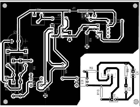
A single-side PCB for the fan speed controller is shown in actual size in Fig -1 and its component layout in Fig -2.After assembling the circuit on the recommended PCB and enclosing it in the suitable case, you can calibrate the system as per your requirements, using VR1.Change VR1 so that, at room temperature, you get the normal speed.
Fig. 2. Component Layout
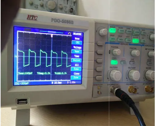
[image:2.595.312.558.506.694.2]with respect to TP0.Trigger pulses for NE555 timer can be observed at TP2 using an oscilloscope. Also verify the pulse width modulated output of NE555 timer at TP3.
[image:3.595.310.555.96.284.2]output of temperature sensor LM35 can be checked at TP4.
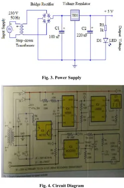
[image:3.595.38.288.111.489.2]Fig. 3. Power Supply
[image:3.595.42.285.493.689.2]Fig. 4. Circuit Diagram
Fig. 5. Main Circuit
The circuit is built around temperature sensor LM35 (IC1), operational amplifier LM358 (IC2), and opto
MCT2E (IC3), timer NE555 (IC4), zero cross photo 29438 International Journal of Current Research,
with respect to TP0.Trigger pulses for NE555 timer can be observed at TP2 using an oscilloscope. Also verify the pulse TP3. The amplified output of temperature sensor LM35 can be checked at TP4.
The circuit is built around temperature sensor LM35 (IC1), operational amplifier LM358 (IC2), and opto-coupler MCT2E (IC3), timer NE555 (IC4), zero cross photo-triac
driver opto-coupler MOC3061 (IC5) and triac BT136 (TRIAC1), along with some other easily a
components.
Fig. 6. Overall Circuit Demonstration
Temperature sensor IC1 senses changes in temperature and its output voltage varies linearly with the variation in temperature. The output voltage of IC1 is amplified using operational amplifier IC2. This amplified voltage is then applied to control voltage pin 5 of IC4, which is wired as a monostable multivibrator.
The control voltage adjusts the threshold and triggering levels of timer IC4 and hence, there are changes in the pulse width of the output waveform corresponding to the voltage level at pin 5 of IC4. The trigger pulses for the monostable multivibrator are produced through IC3. Opto coupler IC3 is wired as a zero
result, a pulse-width-modulated waveform in the output of the monostable multivibrator.
The output pulses of IC4 at pin 3 are applied to anode pin 1 of IC5, which is an optically isolated triac driver with zero crossing detection.
The zero-crossing facility in the triac driver en
firing pulses are applied at exact zero crossing of the AC waveform.
TRIAC1 is one of the most vital component of this circuit; it used to control the speed of the fan by adjusting the RMS value of the AC voltage across the fan.
The firing pulses for TRIAC1 are produced by a monostable multivibrator. The width of these firing pulses varies in accordance with the output voltage of temperature sensor IC1. At a higher temperature, the width of the firing pulses will be more and hence, the RMS
voltage will increase. As a result, the fan will rotate at a higher speed. TRIAC1 is connected with a snubber circuit built around resistor R6 and capacitor C3, to protect it from high-voltage transients.
Performance Analysis
This design has been applied to an AC fan which acts as a load to the circuit. The following observations were observed when the demonstration of the circuit was done
International Journal of Current Research, Vol. 08, Issue, 04, pp.29436-29440, April, 2016
coupler MOC3061 (IC5) and triac BT136 (TRIAC1), along with some other easily available
Overall Circuit Demonstration
Temperature sensor IC1 senses changes in temperature and its output voltage varies linearly with the variation in temperature. The output voltage of IC1 is amplified using amplifier IC2. This amplified voltage is then applied to control voltage pin 5 of IC4, which is wired as a
The control voltage adjusts the threshold and triggering levels of timer IC4 and hence, there are changes in the h of the output waveform corresponding to the voltage level at pin 5 of IC4. The trigger pulses for the monostable multivibrator are produced through IC3. Opto-coupler IC3 is wired as a zero-crossing detector. As a
modulated waveform can be obtained in the output of the monostable multivibrator.
The output pulses of IC4 at pin 3 are applied to anode pin 1 of IC5, which is an optically isolated triac driver with
zero-crossing facility in the triac driver ensures that the firing pulses are applied at exact zero crossing of the AC
TRIAC1 is one of the most vital component of this circuit; it used to control the speed of the fan by adjusting the RMS value of the AC voltage across the fan.
ulses for TRIAC1 are produced by a monostable multivibrator. The width of these firing pulses varies in accordance with the output voltage of temperature sensor IC1. At a higher temperature, the width of the firing pulses will be more and hence, the RMS value of the AC voltage will increase. As a result, the fan will rotate at a higher speed. TRIAC1 is connected with a snubber circuit built around resistor R6 and capacitor C3, to protect it from
The speed of the Fan is SLOW when the temperature of the room is NORMAL.
When there is an increase in the ambient
temperature sensor LM35 senses it. Based on pulse with modulation which can be observed at the output of NE555 timer, the speed of the Fan increases linearly.
When temperature of the room falls below the pre ambient temperature, the fan returns to its normal speed.
During demonstration we have obtained the output based on the speed variation of the fan and also on the digital storage oscilloscope (DSO) based on duty cycle.
The medium speed is attained when there is 50 percent duty cycle and very fast corresponds to 100 percent duty cycle. The variation of the duty cycle with temperature (in Celsius) is shown in the Fig 10. The fan is at very high speed when the duty cycle is 100 percent.
[image:4.595.309.560.50.248.2]demonstration images are as follows.
Fig. 7. Fan Speed is LOW and the Duty Cycle is 10%
Fig. 8. Fan Speed is MEDIUM and the Duty Cycle is 50%
29439 Nigade et al.
The speed of the Fan is SLOW when the temperature of the
When there is an increase in the ambient temperature, the Based on pulse with modulation which can be observed at the output of NE555 timer, the speed of the Fan increases linearly.
When temperature of the room falls below the pre-defined e fan returns to its normal speed. During demonstration we have obtained the output based on the speed variation of the fan and also on the digital storage oscilloscope (DSO) based on duty cycle.
The medium speed is attained when there is 50 percent ycle and very fast corresponds to 100 percent duty cycle. The variation of the duty cycle with temperature (in Celsius) is shown in the Fig 10. The fan is at very high speed when the duty cycle is 100 percent. The practical
Fan Speed is LOW and the Duty Cycle is 10%
[image:4.595.36.293.261.494.2]Fan Speed is MEDIUM and the Duty Cycle is 50%
[image:4.595.310.558.284.465.2]Fig. 9. Fan Speed is HIGH and the Duty Cycle is 100%
Fig. 10. Temperature (in C) vs. Duty Cycle
Fig. 11. Speed vs. Temperature Curve
Nigade et al. Temperature based automatic fan speed controller
Fan Speed is HIGH and the Duty Cycle is 100%
Temperature (in C) vs. Duty Cycle
]
[image:4.595.307.557.294.639.2] [image:4.595.37.292.530.736.2]Fig. 12 .CPU fan embedded on motherboard
Fig. 13. Graphic Card Fan
Conclusion
As the technology is developing day by day we prefer things to be done automatically and in the same way our project reduces the work to mankind. This report has looked at the basic functioning of a fan based and how its speed can be varied with respect to change in the temperature of the environment. The idea of temperature based automatic fan controller is implemented, compatible and highly efficient to reduce the electricity bill and avoid wastage of electricity and also to the people in need i.e. the physically challenged people. In this paper, we have tried to present the best work for the circuit implementation for the design. Based on the waveform obtained in Fig -5, Fig -6, Fig -7 the width of the pulse varies with change in the ambient temperature. Also from the graph obtained in Fig-11 proves that there is a direct linear relationship between the speed of the fan and the ambient temperature.
The speed of the Fan increases with increase in temperature
The speed of the Fan decreases with decrease in temperature
Applications
CPU Fan
As their change in ambient temperature, the speed of the fan changes. The same principle is followed in a CPU. When load of processes and calculations are performed at the same time, the core i.e. the motherboard heats up. Therefore to avoid damage to the motherboard we use CPU Fans The CPU fan is used to cool the heatsink of the northbridge of a motherboard's chipset; this is needed where the system bus is significantly overclocked and dissipates more power.
Graphic Card Fan
The Graphics Card Fan is an extension of the CPU fan. Some computers which are used for gaming purpose require an additional Fan because the power dissipation and heat produces is quite high in this type.
These are used to cool the heatsink of the graphics processing unit or the memory on graphics cards.
Acknowledgement
The authors would like to thank Bharati Vidyapeeth College of Engineering, for supporting our work and to Mrs.A.S.Nigade for transferring and delivering valuable knowledge.
REFERENCES
Malvino, A. P. and Bates, D. J. 2006. “Electronic principles”, McGraw-Hill Publisher, USA.
Mithal, G. K. 1992. “Industrial Electronic”, Khanna Publisher, New Delhi.
Precise Centigrade Temperature Sensor LM35, http://www.ti.com/lit/ds/symlink/lm35.pdf.
Theraja, B. L. and Theraja, A. K. 2005. “A text book of Electrical Technology: AC and DC machines”, S. Chand & Company Ltd. Publisher, New Delhi.
TRIAC BT136 www.nxp.com/documents/ data_sheet/ BT136_ SERIES.pdf