http://wrap.warwick.ac.uk
Original citation:Kerbyson, D. J., Packwood, R. A. and Joy, Mike (2001) Enhancing the learning
environment in experimental laboratories. In: CAL 2001, Coventry, UK, 2-4 Apr 2001 p. 179.
Permanent WRAP url:
http://wrap.warwick.ac.uk/61166
Copyright and reuse:
The Warwick Research Archive Portal (WRAP) makes this work by researchers of the University of Warwick available open access under the following conditions. Copyright © and all moral rights to the version of the paper presented here belong to the individual author(s) and/or other copyright owners. To the extent reasonable and practicable the material made available in WRAP has been checked for eligibility before being made available.
Copies of full items can be used for personal research or study, educational, or not-for profit purposes without prior permission or charge. Provided that the authors, title and full bibliographic details are credited, a hyperlink and/or URL is given for the original metadata page and the content is not changed in any way.
A note on versions:
The version presented here may differ from the published version or, version of record, if you wish to cite this item you are advised to consult the publisher’s version. Please see the ‘permanent WRAP url’ above for details on accessing the published version and note that access may require a subscription.
Automated Progress Identification and Feedback in Large
Experimental Laboratories
D.J. Kerbyson*, R.A. Packwood, M.S. Joy
Department of Computer Science, University of Warwick, Coventry, CV4 7AL, UK
Abstract
In this work we describe a novel web-based system whose aim is to enhance the learning environment within experimental laboratories, and report on its deployment in undergraduate computer architecture modules. Student progress is tracked and recorded throughout the practical work, and supervisory facilities are provided including the visualisation of the progress of everyone in the laboratory on a management console. The system delivers information concerning the practical work to be undertaken, and uses carefully designed sets of questions based on the observations to be made by students in the laboratory. The responses made in this system are used to feedback further specific information to the student to aid their individual progress.
Keywords
applications in subject areas; architectures for educational technology system; interactive learning environments; post-secondary education; teaching/learning strategies;
1. Introduction
The pressure to increase student enrolment in Higher Education is resulting in larger class sizes throughout. Not only does this affect accommodation requirements for plenary lectures, but it also has a large impact on the way in which quality teaching activities may be provided within experimental ‘hands-on’ sessions. Within many science and engineering disciplines the exposure to, and design with, underlying technologies are core teaching activities. However, as class sizes increase, the contact time per student by teaching personnel decreases, thus resulting in the need of enhanced learning environments.
In response to this challenge, we chose to investigate the possibilities for enhancing a first-year undergraduate module on Computer Architecture. The module contains a substantial practical component, in the form of large laboratory sessions, and the number of staff competent to supervise and assist in the laboratories is small. The priorities of a potential solution were identified as being an automated system which would:
• deliver instructional material on demand to the students present; • track the progress of students working through exercise material; and • warn staff of students experiencing difficulty.
* Corresponding author. Email: [email protected].
The attention of staff assisting students would then be more appropriately targeted at those students most in need of help.
This system provides information concerning the practical work to be undertaken, whilst using carefully designed sets of questions based on the observations to be made by students. The responses made in this system are used to feedback further specific information to the student to aid their progress. The software resembles an embryonic expert system, though since the potential material it uses is not restricted to a given subject area a full expert system is not currently envisaged.
This system has many novel features in comparison to others (e.g. Joy & Luck, 1997; Arias & Garcia, 1998), in that it has the capability of tracking and recording student progress throughout the practical work. The monitoring of progress has been achieved, in automated web-based systems, generally at a coarse level for instance in testing knowledge after a sequence of experiments has taken place (e.g. Djordjevic, Milenkovic, & Todorovic, 1999).
The monitoring of progress in this work is undertaken at a fine level, allowing for questioning knowledge, and feeding back information during experimentation. Supervisory facilities are provided that enable the visualisation of progress of everyone in the laboratory on a single management console. This can be used to direct teaching activities to those who require it the most in the laboratory.
The format of Computer Architecture hands-on laboratories is described in Section 2. An overview of the question system is described in Section 3. In particular the
definitions of questions using a configuration of nodes, the transition between nodes, and also the logging of information are discussed in detail. The implementation of the question system is not discussed in detail in this paper. The use of the
management console is described in Section 4.
2. Computer Architecture Laboratories
In dealing with experimental practical laboratories in Computer Architecture, several fundamental concepts are involved which are focused on: hardware components, low-level software programming, and an important interaction between the two – for instance how the software actually affects and uses the hardware (Reinhardt 2000). These are often new concepts to students requiring careful support during the learning process. Several tools have been developed which use the web as the medium of delivery but often lack exposure to hands-on experimentation (e.g Penfold & Flanagan, 2000 and Stegawski & Schaumann, 1998). Integrated systems which incorporate several simulation experiments also are in development (a.g. Kapadia, Fortes & Lundstrom, 2000, and Djordjevic, Milenkovic & Grbanovic, 2000). The access to simulators has also been extended to the notion of interacting with a virtual University (Kapadia, Fortes & Lundstom 2001).
This is a core subject for all Computer Science and related degree with a current enrolment of 260. Each laboratory session involves 130 students, each working in pairs, over a period of three hours per week.
The exercises for this laboratory are centred on the addition of hardware components to an existing small computer system. Using test apparatus, the operation of these additional components can be observed when small test programs are executed on the system. By using an automated question system it is possible to test that observations being made by students are consistent with the exercises being performed. Typically questions with multiple answers are asked of students. When an unexpected answer is given (perhaps due to an unexpected experimental observation), feedback can be automatically given in order to diagnose the cause of the problem. Problems could arise at one of the many parts of the practical experimentation - either from the hardware, the software, or in the use of the test apparatus.
The question system can be used to support both the learning and the teaching activities in this environment. From the learner point of view, an automated system can be used to:
Diagnose problems in the use of the test apparatus, or in the practical experiments
Provide feedback on observations made in the experiment to ensure correctness
Enhance understanding provide information when the teaching content is actually being delivered.
From the teaching point of view, an automated system can be used to:
Monitor Progress a single screen can be used to view progress being made by all students (progress is considered here to be the current question being attempted from an ordered question list).
Identify hot-spots elements of the laboratory that are problematic to many students can be identified (a question
consistently being answered incorrectly for instance).
Provide help to students with poor progress, or to students requesting help (without the need for a hand to be raised!).
An important aspect is to provide information when it is actually required either in the learning process, or to aid teaching activities. This is in contrast to receiving information after the end of a session. This is traditionally achieved by marking laboratory notebooks or using question sheets resulting in feedback that is often too late to correct or develop a better understanding.
3. Question System
The question system consists of two main activities that enhance the teaching and the learning environment within a laboratory. These are:
1. Question and Answer operation – used by students enhancing the learning environment, and
2. Laboratory Status – allowing the interrogation and visualisation of the laboratory activities by the organisers to enhance the teaching activities.
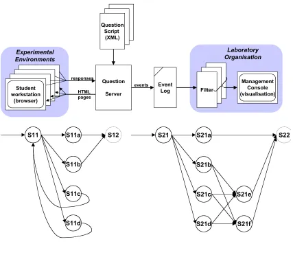
The main components of the question system are shown schematically in Figure 1. The student activities take place in their own experimental environment. Their interaction with the question server is performed using a suitable web-browser on their own workstation. The organiser activities are centered on one (possibly more) instance of a management console. This console allows the activities of the laboratory as a whole to be visualised and interrogated in real-time. Thus at any instant an organiser can view the current progress (or lack) of every student in the laboratory. Progress is viewed by the use of colour cues in such a way that the current exercise being attempted by each student is represented as a different colour.
The question server has access to one or more predefined question scripts, one per available laboratory experiment. Each question script defines a sequence of states
through which a student can traverse whilst doing the exercises contained in a particular laboratory session. States typically involve text/graphic output, which is viewed by the student, as well as a means to progress to one of possibly many further states. Progression, from state to state, requires a response from the student.
The link between the two main activities of the system is the event log. The event log records all activities performed by every student in the laboratory. The event log is constantly monitored by the management console which filters information dynamically (in real-time) for visualisation by the laboratory organisers. The event log is thus written to by the question server, and is read from by the management console.
The system is based on existing web-server technology using the Extensible Mark-up Language (XML) to encapsulate question descriptions, and also transitions between states. The XML question scripts are used by the question server to determine what should be presented to a student when in a particular state, and also how to process responses, made by the student, to determine the transition to a further state. All information passed to a student is in HTML format viewable in their browser.
A node is used to represent both a state and the possible transitions to further states in the XML file. The structure of a node is described in Section 3.1 below. The types of events that are entered into the event log, and their structure, is described in Section 3.2. The extraction of information from the log file is discussed in Section 3.3.
3.1 Question nodes
an identifier a unique character string within the XML question script,
step a number that indicates the step being performed within the exercise,
content consisting of individual text, graphic, and response elements,
actions a list of rules that determine the transition to a further node dependent on the response made to the current node.
The identifier is simply a character string that is unique to the XML question script. It forms a label that can be referred to when specifying a node transition.
The content of a node is a set of elements which are transformed into an HTML page by the question server. Elements can contain text or refer to an image file (in JPEG or GIF format). A response can be associated with each element, that can be used to select the element, or specify a number or text string, in order to answer a question. The grouping of elements is possible, enabling one or more elements to be selected in a response operation (such as is typical in multiple choice style questioning). Grouped elements can be arranged either horizontally or vertically on a page.
Responses that are currently implemented are listed in Table 1. Each response also has a number of associated attributes. A key denotes an attribute which can be referred to when determining a node transition (it is common across elements within a group). A value attribute simply assigns a value to each possible response and is unique within an element group. The label attribute assigns a text string to an HTML style button. The textbox can also be used to enter either textual or numeric information. Further response types can be added, but additional types in the XML question script would be required together with added functionality to the question server to perform the associated operation.
The content of a node is used to specify instructions for the experiment to be carried out prior to asking specific questions. The content of a node can also be specified by reference to a single HTML file. In this case, all formatting and hyper-link information remains intact after passing through the question server. Thus, the HTML file will be displayed without modification on the student workstation.
3.2 Transition between nodes
The transitions possible from one node to another is specified by a list of actions for that node. The actions specify logical rules on the key and value attributes of the response fields of elements contained within the node. Thus it is possible to formulate rules such as, if element one and element four of a group are selected then progress to node A, otherwise progress to node B and so on. Each node must contain an action. In addition equivalence rules for string matching, and numeric ranges (specified by a lower-bound and an upper-bound) can also be used for numeric values.
to S12, and S21 to S22 respectively. Two different structures are apparent in these node configurations both of which are valid. Figure 2a) includes looping back to a previous node (e.g. S11c to S11), whilst Figure 2b) does not have any repeated use of nodes.
The situation depicted in Figure 2a) is represented by the question relationships shown in Table 2 (other relationships are possible). In this case, the multiple choice question in node S11 has four possible responses of which two are correct. On a fully correct answer, responses R1 and R2 are given, resulting in a transition to node S11a. On a part correct answer, response R1 or R2 is given, resulting in a transition to node S11b. A wrong answer results in the transition to node S11c or S11d, and then the question in node S11 repeated in its entirety. Note for each node it is assumed that at most only one element group exists (only one key attribute in use).
A slightly more complex situation arises in Figure 2b). The question relationships for this are shown in Table 3. Here, the question in node S21 has only one correct answer (response R1). On an incorrect response, a further question is presented (either in node S21b, S21c, S21d) having three possible responses. These could in actual fact be similar to question S21 but with the previous incorrect response from S21 removed. If a further incorrect response is given, then node S21f will be reached which is used to state the correct response and progression to the next question in node S22 occurs.
In the XML question script the actual node transition is denoted as a node-change event with an attribute denoting the destination node. A further marker event is used to record when a certain transition between nodes has occurred. A marker can be used to indicate when a question has been answered correctly. The non-existence of a particular marker can be used to deny access to a question. For instance, when questions need to be answered in a given order, a check for a marker from a previous question can be made prior to presenting the requested question to the student.
The structure of nodes in terms of elements, responses, and transition rules provides a flexible framework in which a multitude of question configurations can be constructed. Every event, including node-change events, are recorded into the question server event log. By interrogating the event log, information on the transitions through the question nodes can be obtained. The format of the event log is described in Section 3.3 below.
3.3 Event log
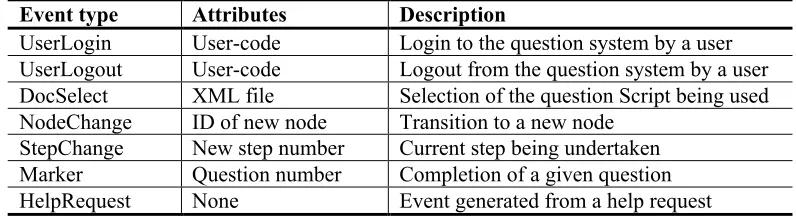
The activities performed by the question server are all recorded in an event log for a particular laboratory session. The format of each entry in this log has the following fields:
Desk ID Time-stamp Event Type Attributes
The attributes of each event are simply text strings. Typically after a user has logged into the question server, a question script will be selected from one of many available. This script is specified for all by the organiser prior to the laboratory session. It is also possible for sub-sets of the laboratory to follow different question scripts and hence perform different experimentation. Node transitions along with step changes record the ID of the new node or step. Steps can be used to represent question numbers and are explicitly labelled in the XML question script.
An additional event not previously mentioned is the HelpRequest. When presenting an HTML page to a student, a menu bar is always present containing a number of facilities including a possible logout and a help request. Thus, help from a laboratory personnel, may be requested at any time. When selecting the help request, a small pop-up window appears on the workstation stating that help will be forthcoming and an event placed in the event log. This event, as well as all others, is interrogated in real-time by the management console.
Two example paths through the question nodes presented in Figure 2a) are shown in Figure 3. Figure 3a) is the shortest path and represents the correct response being given to the question in node S11. In contrast, Figure 3b) illustrates several attempts being taken at the question in node S11. The transitions that take place in this case are actually: S11 to S11c to S11 to S11d to S11 to S11b to S12.
The events recorded in the event log for the transitions shown in Figure 3a) and 3b) are listed below. Events are denoted in bold and their attributes are included in brackets. The DeskID and time-stamp fields have been omitted for brevity.
NodeChange (S11)
Marker (1complete)
NodeChange (S11a)
NodeChange (S12)
StepChange (2)
NodeChange (S11)
NodeChange (S11c)
NodeChange (S11)
NodeChange (S11d)
NodeChange (S11)
Marker (1complete)
NodeChange (S11b)
NodeChange (S12)
StepChange (2)
From these two example event logs it can be seen that the successful completion of the question in node S11 is denoted by the Marker, and that a StepChange occurs on entering Node S12. The repeated attempts at the question in node S11 can be seen in the second event trace in which a NodeChange to S11 occurs three times.
It can be seen from the analysis of the event traces that information concerning the progress of students, and the number of attempts made to each question can be extracted. The filtering and visualisation of this information is described in Section 4 below.
4. Management console
laboratory by interrogating the event log as described in Section 3.3. The management console provides facilities for initialising the question server, installing question scripts, and to view the current status of the system. The main component of this is a representation of the physical arrangement of all experimental environments (or desks) within the laboratory. Each desk is denoted as a rectangle that can be coloured to indicate one of many entities concerning the current status of the laboratory.
An example of the status of the laboratory, using the management console, is shown in Figure 4. This is a screen-shot taken in the middle of a laboratory session. The physical arrangement of desks in the laboratory at Warwick can be seen - a total of 59 desks are in use on this console. Progress through the question script results in the desks gradually getting darker (in this grey scale output). In addition, those desks that have out-standing help requests appear are labelled appropriately.
The visualisation of the laboratory in this way provides a quick and simple way in which problems can be identified by the laboratory organisers. Such problems may occur on either: a single desk (e.g. poor progress by an individual when most others are in an advanced stage of the experimentation), or with the laboratory as a whole (when, for instance, all desks are behind, or in advance of, an expected state at a certain time).
4.1 Information Filtering
All information displayed on the management console needs to be extracted from the event log. This process is undertaken using a filter approach as indicated in Figure 1. A filter reads input from the event log, extracts relevant information, and maps this through a colour table to produce a vector of values, one per desk. This vector is used to colour the desks on the management console. An event added to the event log, by the question server, will cause the filter to update its output information.
A separate filter is responsible for each entity of the question server that can be viewed. The filtering system is extensible - additional filters can be added and selected for use within the management console. The filters are key in providing meaningful information that can be used either in real-time to view the status of the laboratory, or off-line (after the laboratory is closed) to analysis various statistics on question responses. Two filters are currently incorporated into the question server for real-time information are:
Progress the current question step that is being attempted by the student
Correctness the number (or percentage) of questions answered correctly, either at 1st attempt, or over a number of attempts.
NodeVisits the number of times each node was visited (a measure of how many times a question was attempted)
Inter-node Time the time taken from arriving at a node to transitioning to another node (a measure of the complexity of the experimental stage, and/or the question posed).
There is a large amount of information stored within the event log and the design of meaningful information filters is an important consideration. The filters described above are reasonably straightforward in their concept and implementation. However, more complex filters can be envisioned such as identifying the relationships between questions and their own information content. Indeed questions posed on a similar topic may be equally misunderstood. It may be possible to identify when this occurs leading to subject topics to be taught in a different way.
5. Summary
A question system has been implemented whose aim is to enhance the learning and teaching activities within experimental laboratory sessions. The system uses existing web-based technology including XML (Extensible Mark-up Language) question scripts. A question server is used to provide individual information to all students undertaking the laboratory experimentation. By using a configuration of nodes both instructions concerning the experimentation being undertaken, along with carefully designed sets of questions, can be presented to students.
The responses made by students to the question server are used to feedback further specific information to aid progress. When misunderstandings occur, or incorrect observations on the experimentation are made, the question server can be used to correct the situation without the need for laboratory personnel intervention.
All responses from the question server are recorded in an event log. A management console, through the use of information filters, is used to extract information from this event log. The information is presented on a single screen containing a representation of the physical layout of the experimental environments (desks) in use in the laboratory. By colour coding the desks, it is possible to view the current progress of all students in the laboratory, and thus direct quality teaching activities to those who require it most.
The system has been deployed in an experimental laboratory dealing with Computer Architecture with class sizes of 130 students. The system has proved successful in enhancing the flow of information to students when they require it during progression though the experimental exercises. It has also aided the teaching in the provision of support to individual students, and to view the overall progress of the class through the laboratory sessions.
Although designed and used for experimental laboratories, the system is extendable through the addition of further XML question scripts. These could be written for a many modules in different subject areas which require individual student work. The system allows progression at the rate of each individual, and provides information feedback when misunderstandings occur. The system may be used either on mass, within a laboratory environment, or by individuals as and when they wish.
Acknowledgements
The authors gratefully acknowledge the work of James Butler, Phil Müller and Graham McNeil-Watson in the development and coding of the software.
References
Arias, J.R & Garcia, D.F. (1998). Introducing computer architecture education in the first course of the computer science career. Proceedings of Workshop on Computer Architecture Education (WCAE-98), Barcelona.
Djordjevic, J., Milenkovic, A., & Todorovic I. (1999). CALKAS: A Computer Architecture Learning and Knowledge Assessment System, Proceedings of the Workshop on Computer Architecture Education (WCAE-99), Orlando.
Djordjevic, J., Milenkovic, A., & Grbanovic, N. (2000). An integrated Environment for Teaching Computer Architecture, IEEE Micro, 20(3), 66-74.
Kapadia, N.H., Fortes, J.A.B., & Lundstrom, M.S. (2000). The Purdue University Network-Computing Hubs: Running Unmodified Simulation Tools via the WWW.
ACM Transactions on Modeling and Computer Simulation (TOMACS), 10(1), 39-57.
Kapadia, N., Fortes, J., Lundstrom, M. & Valles, D.R. (2001). PUNCH: A
Computing Portal for the Virtual University. International Journal of Engineering Education, 17(2), 207-219.
Joy, M.S. & Luck, M. (1997). Computer-assisted learning using the web.
Proceedings of the 5th Conference on the Teaching of Computing, Dublin, 105-108.
Penfold, J. & Flanagan, J.K. (2000). A first-year computer organization course on the Web: Make the magic disappear. Proceedings of the Workshop on Computer
Architecture Education (WCAE-2000), Vancouver.
Reinhardt, S.K. (2000). Integrating hardware and software concepts in a
microprocessor-based system design lab. Proceedings of the Workshop on Computer Architecture Education (WCAE-2000), Vancouver.
Figure 1: Overview of the question based learning environment
Figure 2: Example configuration of two questions each containing four responses. a) with loops, b) without loops.
[image:12.595.70.497.300.671.2]Figure 3: An example of two different paths through a node configuration. a) correct at first attempt, b) several attempts at the same question.
Figure 4: A screen-shot of the management console showing the status of the laboratory.
Question
Server Student
workstation
(browser) ManagementConsole
(visualisation) Filter
Event Log Question
Script (XML)
Experimental Environments
responses
HTML pages
events
Student workstation
(browser) Student workstation
(browser) Student workstation
(browser)
Laboratory Organisation
S11 S11a
S11b
S11c
S11d
S12 S21 S21a
S21b
S21c
S21d
S22
S21e
S11 S11a
S11b
S11c
S11d
S12 S11 S11a
S11b
S11c
S11d
Response type Attributes Functionality
radiobutton key, value To select one out of a group of elements
checkbox key, value To select one or more out of an element group
textbox key Text entry, one for each group element.
[image:14.595.70.480.85.154.2]nodelink label, key, value Single button - progress to a specified node
Table 1: List of possible response types for content elements.
Node Response Type Possible Responses Transition Rules Remarks
S11 Checkbox R1, R2, R3, R4 S11a: (R1 AND R2) S11b: (R1 OR R2) S11c: (R3 ONLY) S11d: (R4 ONLY)
Multiple choice question with a correct responses of both R1 and R2
S11a Nodelink R1 S12: (R1) Correct answer
S11b Nodelink R1 S12: (R1) Part correct answer
S11c Nodelink R1 S11: (R1) Wrong answer
S11d Nodelink R1 S11: (R1) Wrong answer
[image:14.595.74.482.196.317.2]S12 Next question
Table 2: Node response types and transition rules for the configuration shown in Figure 2a)
Node Response Type Possible Responses Transition Rules Remarks
S21 radiobutton R1, R2, R3, R4 S21a: (R1) S21b: (R2) S21c: (R3) S21d: (R4)
Multiple choice question with one correct
response (R1)
S21a Nodelink R1 S22: (R1) Correct answer
S21b Checkbox R1,R2,R3 S21e: (R1) S21f: (R2 OR R3)
Wrong answer, refined set of possible answers S21c Checkbox R1,R2,R3 S21e: (R1)
S21f: (R2 OR R3)
Wrong answer, refined set of possible answers S21d Checkbox R1,R2,R3 S21e: (R1)
S21f: (R2 OR R3)
Wrong answer, refined set of possible answers
S21e Nodelink R1 S22: (R1) Correct answer
S21f Nodelink R1 S21: (R1) Wrong answer
S22 Next question
Table 3: Node response types and transition rules for the configuration shown in Figure 2b).
Event type Attributes Description
UserLogin User-code Login to the question system by a user
UserLogout User-code Logout from the question system by a user
DocSelect XML file Selection of the question Script being used
NodeChange ID of new node Transition to a new node
StepChange New step number Current step being undertaken
Marker Question number Completion of a given question
HelpRequest None Event generated from a help request
[image:14.595.70.483.373.554.2] [image:14.595.76.474.609.717.2]