Experimental study of a membrane-based dehumidification cooling
system
Ziwei Chen1, Hongyu Bai1, Zihao Ye1, Jie Zhu1*
1
Department of Architecture and Built Environment, University of Nottingham, Nottingham, NG7, 2RD, UK
Abstract: Membrane-based liquid desiccant dehumidification has attracted increasing interests with elimination of solution droplets carryover problem. A membrane-based hybrid liquid desiccant dehumidification cooling system is developed in this study, which has the ability to remove latent load by a liquid desiccant dehumidification unit and simultaneously to handle sensible load by an evaporative cooling unit. The hybrid system mainly consists of a dehumidifier, a regenerator and an evaporative cooler, calcium chloride is used as liquid desiccant in the system. This paper presents a performance evaluation study of the hybrid system based on experimental data. Series of tests have been conducted to clarify the influences of operating variables and conditions (i.e. desiccant solution concentration ratio, regeneration temperature, inlet air condition, etc.) on the system performance. The experimental results indicate that the system is viable for dehumidification cooling purpose, with which the supply air is provided at temperature of 20.4°C for the inlet air condition at temperature of 34°C and relative humidity of 73%. At desiccant solution concentration ratio of 36%, the thermal COPth of 0.70 and electrical COPel of 2.62 are achieved respectively under
steady operating condition.
Keywords: Liquid desiccant dehumidification, Membrane-based, Evaporative cooling
1 Introduction
Desiccant cooling has been regarded as one of the environmental-friendly air conditioning approaches without the shortcomings of overcooling and reheating1. Compared with the solid desiccant system, the liquid desiccant system is more economical and flexible in utilization of low-grade energy sources2 and efficient in providing high quality supply air with independent humidity and temperature controls3. Generally, the selection of a liquid desiccant depends on various operating parameters, such as boiling point elevation, energy storage density, regeneration temperature, thermophysical properties, availability and costs4. Halide salts are the most common liquid desiccants, such as Lithium Chloride (LiCl), Lithium Bromide (LiBr) and Calcium Chloride (CaCl2). Among them, CaCl2 is the cheapest and most
readily available desiccant5. There are various packing types of the liquid desiccant system, such as wetted wall, spray tower, packed column and membrane-based6. The membrane-based system using an indirect contact for dehumidification has been more attractive with elimination of solution carryover problem. Membrane acting as a selective barrier allows heat and moisture transfer between solution and airstream, and meanwhile prevents the entrainment of liquid desiccant7.
Various experimental studies on the membrane-based liquid desiccant dehumidification system have been conducted. Abdel-Salam, et al.8 proved the feasibility of a membrane-based desiccant air conditioning system powered by solar
energy. El-Dessouky, et al.9 proposed a novel air conditioning system integrating a membrane dehumidification unit with an indirect/direct evaporative cooler, and found that 86.2% energy saving can be achieved compared with a stand-alone vapour compression system. Jradi and Riffat10 developed a hybrid dehumidification cooling system, with which the supply air temperature and humidity reduce from 33.8℃ to 22.3℃ and 68.6% to 35.5% respectively. Regarding to the membrane-based liquid desiccant dehumidification cooling system, few researches have been carried out for feasibility study and performance evaluation through experimental work. In this study, a membrane-based hybrid dehumidification cooling system is built for experimental investigation. The system feasibility and performance are evaluated under various operation conditions; the influences of inlet air condition, desiccant concentration and regeneration temperature on the system performance are investigated based on the experimental results.
2 Experimental set-up
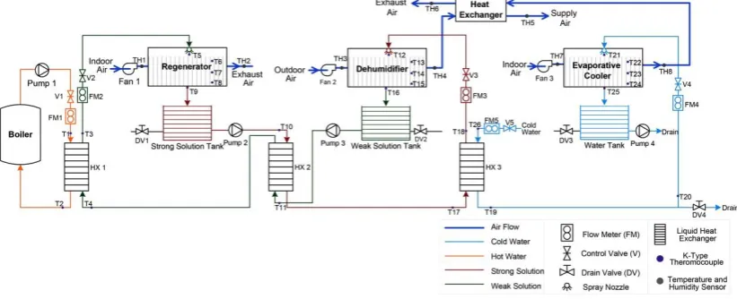
The hybrid system consists of four main components: a dehumidifier, a regenerator, an evaporative cooler and an air-to-air heat exchanger, as illustrated in Figure 1. Three processes are involved in the system, namely: dehumidification, regeneration and evaporative cooling. The cool airstream from the evaporative cooler is used to cool the dry air to meet the supply requirement in the air-to-air heat exchanger. After dehumidification, the solution is dilute and flows directly to the weak solution storage tank. A magnetic-driven pump delivers the diluted solution from the storage tank to a heat exchanger (HX2), where the weak solution is pre-heated before being heated by hot water. Cold water cools the strong desiccant solution prior to flowing into the dehumidifier and then flows directly into the evaporative cooler. Aqueous CaCl2
[image:2.595.95.506.452.619.2]solution is used for experiment.
Figure 1 Schematic graph of the membrane-based dehumidification cooling system
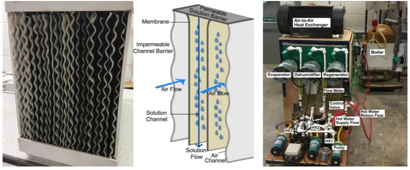
Figure 2 Illustration of the membrane-based unit Figure 3 Test rig photo
2.1 Method
[image:3.595.94.501.71.240.2]The system test rig is shown in Figure 3, insulation is applied for air ducting, pipe work and heat exchangers to reduce the surrounding effects. Main experimental equipment with their specifications is listed in Table 1.
Table 1 Specifications of main equipment
Equipment Properties Manufacturer
Magnetic pump Power 15 W Shanghai Jiaxing Pumps Co., Ltd.
Maximum frequency 50 Hz Maximum speed 2600 r/min Maximum capacity 10 L/min
AC axial fan Power 45W ebm-papst Mulfingen GmbH & Co. KG Nominal speed 2800 min-1
Boiler Capacity 3kW
Supply temperature range 50-80°C Water storage 120 Litre
Circulating pump 45W Wilo SE Water flow rate 6 L/min
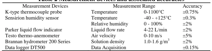
All inlets and outlets are instrumented with humidity and temperature probes and desiccant solution and water flows are instrumented with K-type thermocouples. Air velocities are measured with an anemometer. The main measurement devices and associated accuracies are indicated in Table 2. The solution density is measured with a hydrometer and a correlation determined by Melinder11 is used to calculate CaCl2
solution concentration ratio based on the solution density and temperature. Desiccant solution/water volumetric flow rates are measured by liquid flow indicators. The float style flow meters are generally calibrated with water at 20°C according to density and dynamical viscosity, so a correction correlation is used to equate the volumetric flow rate reading from the flow meter to the actual desiccant solution flow rate in the dehumidifier/regenerator unit12.
float float sol w sol w
float float w sol
( )
( )
m V
v v
m V
(1)
where, vsol and vw are volumetric flow rates of the desiccant solution and water
[image:3.595.86.511.346.491.2]Table 2 Measurement devices and associated accuracies
Measurement Devices Measurement Range Accuracy K-type thermocouple probe Temperature 0-1100°C ±0.75% Sensirion humidity sensor Temperature -40 - +125°C ±0.3%
Relative humidity 0 - 100% ±2% Parker liquid flow indicator Liquid flow rate 4-22 L/min ±2% Testo thermo-anemometer Air velocity 0-10 m/s ±5% Brannan hydrometer 200 Series Solution density 1.0-1.6 g/m3 ±2% Data logger DT500 Data Acquisition ±0.15%
Uncertainty analysis provides the associated error measure of a calculated value using the given equation. Error bars are included in the graphs for experimental result analysis. 2 2 1 ( )
i N y x i i y U Ux (2)
where, Uxi is uncertainty of each measured variable xi. 2.2 Performance evaluation metrics
Dehumidification process
The dehumidification performance is evaluated by moisture removal rate.
r air_DH ( in_DH out_DH)
M m (3)
where, Mr represents moisture removal rate, g/s. mair_DH is mass flow rate of air
passing through the dehumidifier, kg/s, in_DH and out_DH are air humidity ratios at the inlet and outlet of the dehumidifier, kg/kgdryair. Thermophysical properties of the
moist air are determined using equations defined by Tsilingiris13.
The dehumidification effectiveness is defined as the ratio of actual change in moisture content to the maximum moisture transfer.
in_DH out_DH DH in_DH eq_DH
(4)
where, DH is the dehumidification effectiveness. eq_DH is equilibrium humidity ratio of desiccant solution at the inlet condition, kg/kgdryair. Under the equilibrium state, it is
given as14:
sol eq_DH
A sol
0.62198 P
P P
(5)
where, PA is atmospheric pressure, Pa, and Psolis vapour pressure of CaCl2 solution at
given temperature, Pa, which can be calculated with the empirical correlation derived by Cisternas and Lam15.
Based on the enthalpy difference of the inlet and outlet air in the dehumidifier, the dehumidifier cooling output is determined as:
DH_cooling air_DH( in_DH out_DH)
Q m h h (6)
where, QDH_coolingis the dehumidifier cooling output, W. hin_DH and hout_DH are specific
enthalpies of inlet air entering the dehumidifier and leaving the dehumidifier, J/kg.
Regeneration process
The regeneration performance is evaluated by moisture addition rate.
a air_RE ( out_RE in_RE)
where, Ma represents moisture addition rate, g/s. mair_RE is air mass flow rate passing
through the regenerator, kg/s. in_RE andout_RE are air humidity ratios at the inlet and
outlet of the regenerator, kg/kgdryair.
The thermal input of the regenerator is determined as:
RE w_RE p_w_RE( w_f w_r)
Q m c T T (8)
where, QREis the regenerator thermal input, W. mw_REand cp_w_RE are water mass flow
rate, kg/s, and specific heat capacity, J/kg, in the heating circuit. Tw_fand Tw_r are hot
water supply and return temperatures respectively, °C.
Coefficient of performance
The total cooling output of the hybrid system is expressed as:
cooling air_DH( in_DH supply)
Q m h h (9)
where, Qcooling is the system total cooling output, W. hsupplyis specific enthalpy of
supply air, J/kg.
The hybrid system overall coefficients of performance (COP) are defined as:
cooling th
RE
COP Q
Q
(10)
cooling el
e
COP Q
W
(11)
where, COP is thermal coefficient of performance and th COP is electrical coefficient el
of performance. We is electrical consumption, W.
3 Results and Discussion
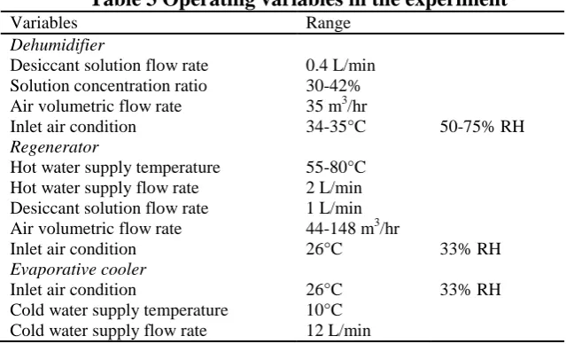
[image:5.595.138.458.525.719.2]Table 3 presents the operating variables for the experiment. The effects of operating variables on the dehumidifier and regenerator performances are investigated with CaCl2 solution concentration ratio of 39%.
Table 3 Operating variables in the experiment
Variables Range
Dehumidifier
Desiccant solution flow rate 0.4 L/min Solution concentration ratio 30-42% Air volumetric flow rate 35 m3/hr
Inlet air condition 34-35°C 50-75% RH Regenerator
Hot water supply temperature 55-80°C Hot water supply flow rate 2 L/min Desiccant solution flow rate 1 L/min Air volumetric flow rate 44-148 m3/hr
Inlet air condition 26°C 33% RH Evaporative cooler
Inlet air condition 26°C 33% RH Cold water supply temperature 10°C
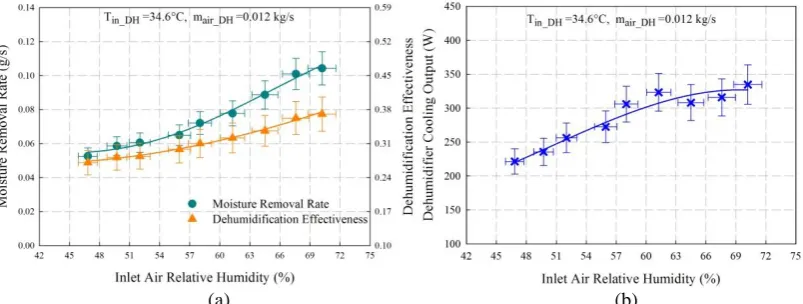
3.1 Effect of inlet air relative humidity on dehumidification performance
The inlet air temperature for the dehumidifier is set at 34.6°C and relative humidity varies from 46% to 70%. It can be seen from Figure 4(a) that the dehumidifier performance increases with the inlet air relative humidity at the same inlet air temperature. The dehumidifier moisture removal rate doubles as air relative humidity increases from 46% to 70% and the dehumidification effectiveness improves by 36.91%. The increase in the dehumidifier moisture removal rate is caused by the greater vapour pressure difference between the airstream and desiccant solution.
[image:6.595.96.498.201.353.2](a) (b)
Figure 4 Effects of inlet air relative humidity on (a) moisture removal rate and dehumidification effectiveness and (b) dehumidifier cooling output
Over the investigated inlet air relative humidity range, the higher inlet air relative humidity leads to more cooling output as shown in Figure 4(b). The dehumidifier cooling output increases from 221.37W to 334.67W as air relative humidity increases from 46% to 70%. However, as the relative humidity gets higher than 63%, the increase in the cooling output becomes smaller. It indicates that with further increase in air relative humidity, the dehumidifier cooling output is approaching the maximum capacity.
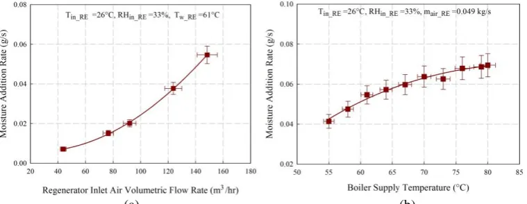
3.2 Effect of air flow rate on regeneration performance
(a) (b)
Figure 5 Effects of (a) air flow rate and (b) hot water supply temperature on moisture addition rate
3.3 Effect of hot water supply temperature on regeneration performance
To identify the effect of hot water supply temperature on regeneration performance, the hot water temperature is set in the range from 55°C to 80°C. As presented in Figure 5(b), the regeneration performance improves gradually with the hot water supply temperature. The moisture addition rate increases by 75% as the hot water supply temperature increases from 55°C to 80°C. The increase in the hot water supply temperature results in higher desiccant solution temperature in the regenerator, and thus higher vapour pressure is obtained in solution side. Then the greater vapour pressure difference between the desiccant solution and airstream leads to more mass transfer in the regeneration process at the same inlet air condition. Moreover, as the hot water supply temperature is above 70°C, the increase in the moisture addition rate becomes slow. The variation in the air humidity ratio across the regenerator is only 0.06g/kgdryair as the temperature increases from 70°C to 80°C. Therefore, regarding to
the feasibility of integrating renewable energy for thermal input, at the given operating condition, hot water supply temperature up to 70°C is sufficient for adequate regeneration performance.
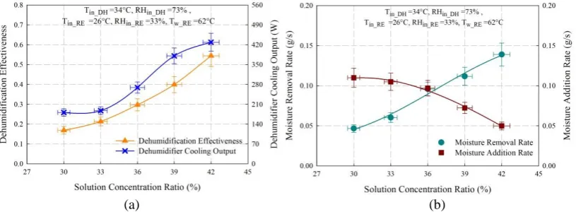
3.4 Effect of concentration ratio on system performance
According to the operative concentration level of CaCl2, investigations have been
conducted with solution concentration ratio from 30% to 42%. The dehumidification effectiveness increases with solution concentration ratio as shown in Figure 6(a). For desiccant solution concentration ratio below 33%, there is only slight difference in the dehumidifier effectiveness, which implies the operative concentration ratio needs to be at least above 33%. As solution concentration ratio gets higher than 33%, the dehumidifier effectiveness improves more significantly and reaches up to 0.54 for concentration ratio of 42%. For operation of the liquid desiccant system, higher desiccant solution concentration ratio would be better for dehumidification performance. However, the use of highly concentrated solution may cause salt crystallization, which may lead to risks of fluid mal-distribution, channel blockage, high pumping pressure, and membrane fouling. On the other hand, the dehumidifier cooling output also increases from 180.99W to 428.78W with increase of solution concentration ratio, which is related to the higher moisture removal rate in the dehumidifier.
increases from 30% to 42%, the dehumidifier’s moisture removal rate improves from 0.05 g/s to 0.14 g/s while the regenerator moisture addition rate decreases from 0.11 g/s to 0.05 g/s. For the dehumidification process, the driving force caused by the vapour pressure difference between airstream and desiccant solution gets higher for stronger solution, which thus leads to greater moisture removal rate in the dehumidifier. On the contrary, in the regeneration process, the desiccant solution with higher concentration ratio has lower capability for moisture addition due to the lower vapour pressure.
To allow continuous operation of the dehumidifier, the performance of regenerator should match with that of dehumidifier as the mass imbalance issue would result in problems such as the dilution of desiccant solution over time. For the investigated operating condition, the dehumidification and regeneration processes are balanced at desiccant solution concentration ratio of 36%, as the dehumidifier moisture removal rate matches the regenerator moisture addition rate. Thus, measures are needed to facilitate the regenerator performance for the stronger desiccant solution and the dehumidification performance should be improved at lower concentration ratio. Under the system steady operation condition, the thermal COPth and electrical COPel reach
up to 0.70 and 2.62 respectively at concentration ratio of 36%, while the supply air temperature is provided at 20.4°C. Hence, the results reveal that the hybrid system is feasible for applications, and the supply air condition could meet the comfortable indoor environment requirement.
[image:8.595.96.504.369.519.2](a) (b)
Figure 6 Effects of solution concentration ratio on (a) dehumidification effectiveness and cooling output and (b) moisture removal and addition rates
4 Conclusion
A membrane-based hybrid liquid desiccant dehumidification cooling system has been developed to provide efficient temperature and humidity controls in the hot and humid regions. The experimental results indicate the system with CaCl2 desiccant solution is
of 34°C and relative humidity of 73%. The thermal COPth achieves up to 0.70 and the
electrical COPel reaches to 2.62 with CaCl2 desiccant solution concentration ratio of
36%.
Acknowledgements
The authors gratefully acknowledge the scholarship support from the Faculty of Engineering of the University of Nottingham.
References
1. Daou, K., Wang, R. & Xia, Z. Desiccant cooling air conditioning: a review.
Renewable and Sustainable Energy Reviews10, 55-77 (2006).
2. Wang, X., Cai, W., Lu, J., Sun, Y. & Ding, X. Heat and Mass Transfer Model for Desiccant Solution Regeneration Process in Liquid Desiccant Dehumidification System. Industrial & Engineering Chemistry Research 53, 2820-2829 (2014).
3. Zhang, L.-Z. Progress on heat and moisture recovery with membranes: From fundamentals to engineering applications. Energy Conversion and Management63, 173-195 (2012).
4. Ahmed, S.Y., Gandhidasan, P. & Al-Farayedhi, A.A. Thermodynamic analysis of liquid desiccants. Solar Energy62, 11-18 (1998).
5. Mei, L. & Dai, Y.J. A technical review on use of liquid-desiccant dehumidification for air-conditioning application. Renewable and Sustainable Energy Reviews12, 662-689 (2008).
6. Qi, R., Lu, L. & Jiang, Y. Investigation on the liquid contact angle and its influence for liquid desiccant dehumidification system. International Journal of Heat and Mass Transfer88, 210-217 (2015).
7. Huang, S.-M. & Zhang, L.-Z. Researches and trends in membrane-based liquid desiccant air dehumidification. Renewable and Sustainable Energy Reviews28, 425-440 (2013).
8. Abdel-Salam, A.H., Ge, G. & Simonson, C.J. Thermo-economic performance of a solar membrane liquid desiccant air conditioning system. Solar Energy
102, 56-73 (2014).
9. El-Dessouky, H.T., Ettouney, H.M. & Bouhamra, W. A Novel Air Conditioning System. Chemical Engineering Research and Design 78, 999-1009 (2000).
10. Jradi, M. & Riffat, S. Experimental investigation of a biomass-fuelled micro-scale tri-generation system with an organic Rankine cycle and liquid desiccant cooling unit. Energy71, 80-93 (2014).
11. Melinder, Å. Thermophysical Properties of Aqueous Solutions Used as Secondary Working Fluids [Elektronisk resurs], (KTH, Stockholm, 2007). 12. Liu, S. University of Nottingham (2008).
13. Tsilingiris, P.T. Thermophysical and transport properties of humid air at temperature range between 0 and 100 °C. Energy Conversion and Management49, 1098-1110 (2008).
15. Cisternas , L.A. & Lam, E.J. An analytic correlation for the vapour pressure of aqueous and non-aqueous solutions of single and mixed electrolytes. Part II. Application and extension. Fluid Phase Equilibria62, 11-27 (1991).
Nomenclature
p
c Specific heat capacity (J/kg.K) Greek symbols
h Specific enthalpy (J/kg.K) DH Dehumidification effectiveness m Mass flow rate (kg/s) Density (kg/m3)
float
m Flow meter float weight (kg) Air humidity ratio (kg/kgdryair)
a
M Moisture addition rate (g/s)
r
M Moisture removal rate (g/s) Subscripts
P Pressure (Pa) air Air
cooling
Q Total cooling output (W) eq Equilibrium state
DH_cooling
Q Dehumidifier cooling output (W) in Inlet
RE
Q Regenerator thermal input (W) out Outlet
T Temperature (°C) S Saturation
w_f
T Hot water supply temperature (°C) sol Solution
w_r
T Hot water return temperature (°C) w Water
i
x Measured variable
x
U Measured variable uncertainty Abbreviations
y
U Variable uncertainty COP Coefficient of performance v Volumetric flow rate (L/min) DH Dehumidifier
float
V Flow meter float volume (m3) EV Evaporative cooler
e