Design and Construction Objects Store System using
Line Follower Robot
Abdulmuttalib T. Rashid
Electrical Engineering Dept.
University of Basrah
Basrah, Iraq
Fatima R. Ali
Electrical Engineering Dept.
University of Basrah
Basrah, Iraq
Osama T. Rashid
Computer Engineering Dept.
Iraq University Collage
Basrah, Iraq
ABSTRACT
In this paper, a new method for objects store in static environments, referred to as objects store system, is designed and constructed. This system consists of thirty boxes arranged in four columns to store and retrieve objects using the line follower robot. The storing and retrieving process is investigated by using a differential drive mobile robot which equipped by left and right infrared sensors to work as line follower robot. The trajectories of this robot is arranged according to the N-ary tree algorithm and enhanced by using the digital differential algorithm DDA to reduce the rabble occurrences. The address of each store box is considered as an access code with five binary digits which protect by using the radio frequency identification module (RFID). The objects store system is implemented on two experimental scenarios, one of them is used to test the time of arrival with respect to the number of store boxes and the other is used to test the average length of the paths.
General Terms
Differential drive mobile robot, Object store system.
Keywords
Objects store system, Line follower robot, RFID module, N-ary tree algorithm.
1.
INTRODUCTION
An automated stored/retrieved system (AS/RS) is a necessary system in automation techniques because it is designed to ensure more speed, more accuracy and to increase the flexibility in performing both store and restore operations [1]. The main purpose of the object storage system is to handle the situation when there is a large amount of objects need to store and restore within a shortest time [2]. There are many kinds of objects store system where the division of them depending on their size and the size of objects to be stored and retrieved. There are many basic types of the AS/RS [3]:
1.Unit-load: This system can be defined as a large automated system that designed to handle with the loads that stored on the pallets or in other containers.
2.Deep-lane: This system is one of the most appropriate systems when there are large amounts of things to be stored, so this system can be considered as a high-density system.
3.Mini-load: This type of storage system is smaller than the Unit-load system.
4.Man-on-board: In this system, a human operator manually does the process of retrieving items from their storage locations.
5.Automated item-retrieval system: This system is also designed to retrieve an individual objects.
The crane based AS/RS is the early version of AS/RSs which has one machine for storage and retrieval in each path and can only carrying one product at a time [4]. Since, the machine with one crane is limited; the multi-shuttle cranes can be used to increase the capacity of storing, so the amount of objects to be stored will be also increased. From 1950 up to now, the AS/RS can be defined as warehousing systems, it is used to store and retrieve objects automatically. The main advantages of these systems are savings in the place, reducing the error rate and increasing the reliability. The main disadvantages are reducing the flexibility, increasing the costs and require high control systems [5]. In 2012, H. J.Carlo, et.al [6], introduces a new AS/RS known as a dynamic storage system. This system consists of two lifts working in sequence to prevent them from colliding with each other. When there is a request for storing or restoring an item, this command will send to the both lifts, and any one of the lifts responds to this command depends on it is status busy or not busy. In 2014, J. Gagliardi, et.al [7], design and improve an automated storage and retrieved system. The operation way of this system wills effects on its efficiency. Also this design discussed that the performance of the system depend on the sequence of the request (the stored and retrieved operations perform according to a specific order). In the designed system the problem of sequencing and storage location solved by using a "sequencing mathematical model" (SMM). The drawback of the SMM it is not considered the best solution for all the designed storage systems.
Line follower robots can be used in motion trajectory to design the object storage system [8-11]. Also the performance of the robot can be increased by assuming that the line follower robot travels along a predetermined path that determined by some nodes [12]. One of the advantages of invention of line following property is that the vehicles can drive properly [13]. Recently the line follower robots have been used in many fields. For example, the line follower robots can be used to transport building materials or to transport luggage and that is why the design of this type of robots will be increased [14].
In this paper the object store system is designed to store and retrieve objects with several boxes. A differential drive mobile robot is used as a line follower robot to store and retrieve object. The rest of the paper organized as follows: Section 2 explains the object store system, section 3 describes the object store system construction in details, section 4 shows the system software, experimental results shown in section 5 , and finally section 5 discuss the results.
2.
THE OBJECTS STORE SYSTEM
system environment has thirty boxes arranged into two groups and each one has 15 boxes. The store system has the information about the address and the status of each box (full or empty). The address of each box is represented by a unique code number consist of five binary digits which divided into three parts: Dir1, Dir2 and Cross. Dir2 (LSB) is used to rotate the robot to the right group of the boxes (Dir2=0) or to the left group (Dir2=1), Dir1 (the second bit) is used to rotate the robot to the right sub group of the boxes (Dir1=0) or to the left sub group (Dir1=1) and Cross (the last three MSB) represents the number of each cross (numbered from 0 to 7) at each group of the boxes. For storing or restoring process, at first, the store system detects any request for storing or retrieving an object then finds the location of the desired box for the request process and gives the order to the line follower robot to move to that box to execute the task. For storing task the robot pick up the object from the start location and transfer it to the store box then return to begging position. For retrieving task the robot move to the desired box and pick up the object then return to the start position to arrive the object.
Fig 1 Experimental setup infrastructure.
All the robot trajectories are represented by linear paths drawn according to the DDA algorithm [15, 16]. The DDA algorithm is used to aim the mobile robot to follow either a straight or arc trajectories. In this algorithm the coordinate axis computation of each point is depending on the coordinate axis of the last point. The DDA algorithms eliminate the number of multiplications by using the raster characteristics; therefore, it is faster than the direct line equation in determining the line pixels.
3.
THE SYSTEM HARDWARE
The system hardware consists of line follower robot, store system and thirty store boxes placed on a white board of 120cm long and 120cm wide. The following is an explanation of how to design and construct the hardware parts.
3.1
Robot Construction
[image:2.595.56.282.283.512.2]The robot used in this system is a differential drive mobile robot [17]. This robot is designed to work as a line follower robot to store and retrieve objects (mobile phone. This robot has a circular shape (Fig. 2) with 15 cm diameter and consists of three main parts: The mechanical board, the object catcher
Fig 2: The differential drive mobile robot.
Part one: The mechanical board
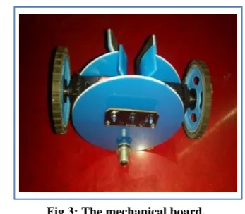
The mechanical board is designed with one caster edge and two wheels connected to continuous servo motors to control the movement of the mobile robot as shown in Fig. 3. The servo motor is defined as electric devices that can use for rotate an object in a high accuracy. There are two types of servo motors depending on the driven power: the DC servo motor and the AC servo motor. Also, these servos can be classified according to their continuous movement into two types:
1.Standard servo motor: This type of motor can rotate at 180o, 120o and 0o in both directions.
2.Continuous Servo Motor: This type of motor can rotate from 0o to 360o in both directions.
Fig 3: The mechanical board.
[image:2.595.339.513.373.525.2]Fig 4: Servo position for pulses with different widths.
[image:3.595.107.227.284.391.2]Two independent servo motors are used to actuate the two active wheels of the robot. In particular, we used the DS04-NFC Continuous Rotation Servo as shown in Fig. 5.
Fig 5: DS04-NFC servo motor.
Part two: The object catcher
[image:3.595.318.544.314.675.2]This part consists of a slot and two arms fixed on two small servo motors to catch the object in vertical direction as shown in Fig. 6.
Fig 6: The object catcher.
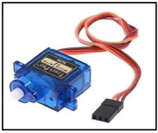
[image:3.595.79.256.445.602.2]The servo motors used in this part are the Micro Servo Motors as shown in Fig. 7.
Fig 7: Micro Servo Motor.
Part three: The control part
This part is used to control the movement of the robot through the storing and the retrieving operations. The control part consists of the Arduino Uno microcontroller, the RF 315/433 MHz, the obstacle detector sensor, 9 Volt Battery and the Line Tracker sensors.
The Arduino is an electronic development board that can communicate with the surrounding environment through a number of sensors. It can affect its surroundings by controlling motors, small lights and other electronic parts. There are more than 30 types of Arduino boards (such as Arduino Uno, Arduino Nano Top, Arduino Mega) that vary in shape, size and price to suit all. We used the Arduino Uno in the control circuit of the robot. Arduino Uno (Fig. 8) is the most commonly used in building a projects, it provides ports to connect electronic components such as sensors to the controller directly via 14 digital IN / OUT pins. Six ports can be used for Pulse-Width modulation. The circuit also has a 16MHz Crystal Oscillator, a USB port for communication with the computer, and a separate power input [18]. Fig. 9 and Fig. 10 show the control part and it is schematic diagram respectively.
Fig 8: Arduino Uno board.
Fig 9: The control part.
[image:3.595.112.224.633.727.2]Fig 10: The schematic diagram of the control part.
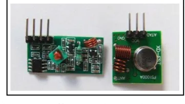
[image:4.595.74.255.494.596.2]In this work we used the RF 315/433 transmitter-receiver module to send and received the commands between the control center and the robot. At the transmitter, the electromagnetic waves should be modulated by the robot control data. There are many modulation techniques used for this purpose such as ASK, OOK, DSSS, FSK, FHSS and GFSK. The choice of the modulation technique depends on the application and requirements. The modulation technique used in this 315/433 MHz RF module (Fig. 11) is ASK (Amplitude Shift Keying) which is the most widely used modulation technique in low band radio communications.
Fig 11: RF 315/433 transmitter-receiver modules.
At the receiver, an inverse process called demodulation is done using the same ASK technique and the data is extracted from the carrier wave. The maximum distance between the transmitter and the receiver of the 315/433 MHz RF modules is not more than 90 meters in open area.
The differential drive mobile robot is equipped by the line tracker sensor (Fig. 12) to works as a line follower robot to be able to reaches any store box by following the straight lines drawn on the environment. Line tracker sensor consists of three pairs of IR (Infra-red sensors) transmitter and IR receiver. This tracker can be used to detect either black or bright line following. This sensor contains three digital outputs to indicate the presence of the line. Every sensor
Fig 12: The line tracker sensor.
[image:4.595.356.500.557.642.2]Infra-red sensors is an electronic devices that sensing the surroundings by emitting and detecting an infrared radiation, as shown in Fig. 13 [19]. This sensor is used for line tracking purpose by differentiating white and black color.
Fig. 13: Infra-red transmitter and receiver sensors.
(a) (b)
Fig 14: The operation of the infrared sensor; (a) white surface (b) black surface.
In the storing and retrieving tasks the robot must know when it reaches to the desired box. This problem is solved by adding an IR obstacle detection sensor (Fig. 15) on the robot to senses the arrival of the mobile robot.
[image:5.595.332.526.166.345.2]Battery or energy is an important issue especially in the mobile robot. There are many types of batteries can be used in robots, such as alkaline batteries. Alkaline batteries characterized by high energy density and long shelf life.
Fig 15: The IR obstacle detector sensor
3.2
The store system
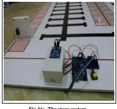
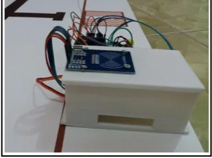
The store system has several tasks: check status of the RFID reader and control the distribution of the RFID Tags, check the status of each store box and control the mobile catching process, and gives the orders to the mobile robot to move to the desired store box. The store system consists of three parts: the control unit, RFID identity unit and the store boxes as shown in Fig. 16.
Fig 16: The store system.
Part one: The control unit
This unit is an electronic device fixed at the lower left corner of the environment. All the process of identification through the RFID part and storing/retrieving of an object are controlled by this unit. Fig. 17 and 18 show the control unit and it is schematic diagram.
[image:5.595.115.222.280.369.2] [image:5.595.93.515.436.724.2]Fig 18: The control unit.
The control unit consists of the Arduino Mega 2560 microcontroller, RF 315/433 MHz, and 9 Volt Battery. The same types of the RF module and the 9 Volt Battery that used in the robot also are used in this control center. The largest and best Arduino can be obtained is Arduino Mega 2560 because it has the largest memory and it has inputs and outputs pins more than the others types. The Arduino Mega 2560 card is based on the ATMEGA 2560 microcontrollers and contains 54 connectors (inputs and outputs), 14 of which can be used as an output for the PWM communication channel, 16 analogues (I/O) and a crystal oscillator at 16MHz. It can be connected to the computer simply by USB cable or even using a battery to make it work [20].
Part two: The RFID identity unit
The object store system is designed with very secure identification system. This system depends on the RFID technics (Radio Frequency Identification) which provides a secure, reliable, simple and very trusted method for storing and retrieving any object. RFID can be defined as an automatic identification technique that uses electromagnetic fields of radio frequencies to identify objects that carry tags when approaching from the reader. RFID consists of two electronic circuits, the first called the reader and the other called the tag. These two circuits connect wirelessly using radio waves. The reader consists of transceiver and antenna, and this circuit needs a source of energy to operate, while the tag is a very precise electronic circuit and need very little energy to feed even it does not contain a source of energy. The distance allowed between the reader and the tag through which the reader can read the tag up to several feet. When the tag is rounded from the reader (less than 5 cm) the electromagnetic waves of the reader overlap with the tag, an inductive current is generated within the tag circuit with very little power but enough to operate. The reader then reads the information stored on the tag [21]. In this paper the RC522 Passive RFID Module is used for identification. The RFID unit has two parts: The RFID tags store box and the RFID reader (Fig. 19).
The maximum capacity of our store system is 30 objects, so that the RFID tags store box is designed to store 30 tag cards. The box has dimensions: 12*8*5 Cm with two horizontal holes as shown in Fig. 20. The upper one which it near the RFID reader is used to enter the card of the retrieving object and the lower one is used to out the card of the storing object. Servo motor with arm is used to the exit process of the storing cards. The cards inside the store box are cumulated as a stack of cards which works according to the principle of the first in first out.
[image:6.595.347.512.180.327.2](a) (b)
Fig 20: The box of the RFID; (a) upper side (b) lower side.
Part three: The store boxes
The object store system is designed with 30 store boxes arranged according to the N-ary tree algorithm in a static environment. Each box equipped with a servo motor with arm to mask the arrival object which represents by a mobile phone as shown in Fig. 21. The same servo motor used by the RFID identity unit is used by each store box.
(a) (b)
Fig 21: The store boxes; (a) the store box (b) storing a mobile phone.
4.
THE SYSTEM SOFTWARE
The system software consists of two programs: one is stored in the line follower robot to control it is movement and the other is stored in the control unit to control all the operation that executed in the object store system.
A.
The Software of the Line Follower Robot
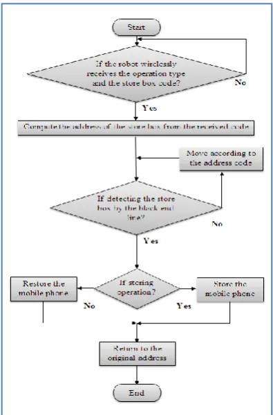
[image:6.595.346.510.427.580.2] [image:6.595.90.245.635.750.2]the movement, the robot checks it is IR obstacle detection sensor for knowing if it arrivals to the desired box. When the robot reaches to the desired box, the acknowledgment signal is sends to the control unit to give a suitable action. If the operation is storing then the store box mask the mobile by rotating it servo motor and the robot rotate it object catcher servos to leaves the mobile. When the operation is restoring then the robot rotate it object catcher servos to mask the mobile phone and the store box leaves the mobile by rotating it servo motor. After that the robot moves in reverse direction to return to the original position. Fig. 22 illustrates the flow chart of the line follower robot program.
B.
The Software of the control unit
[image:7.595.328.530.69.374.2]This software is loaded on the microcontroller of the control unit and used to control the process of the storing and retrieving the mobile phones. At first the control unit is continuously checks the status of RFID reader and the first position to storing the mobile phone to distinguish if there are any storing or retrieving operations. For restoring operation the control unit reads the code of the inserted RFID tag to restore the compatible code of the address from the file used for this purpose. For storing operation the control unit searches the store file which contains the address codes and the status of each store box to finds the nearest empty box. After that the control unit sends the address code of the desired box and the type of operation wirelessly to the line follower robot and waits for receiving the acknowledgment signal when the robot reaches to the desired box. When the robot sends the acknowledgment signal the control unit sends an action either to mask the mobile phone for the storing operation or leave the mobile phone for the restoring operation. Fig. 23 shows the flow chart of the control unit program.
[image:7.595.69.267.425.725.2]Fig 22: The flowchart to the line follower robot software.
Fig 23: The flowchart to the control unit software.
5.
THE EXPERIMENTAL RESULTS
The Experimental results are obtained by using static environment consists of line follower robot with 30 store boxes placed on a white board of 120cm long and 120cm wide as shown in Fig. 24.
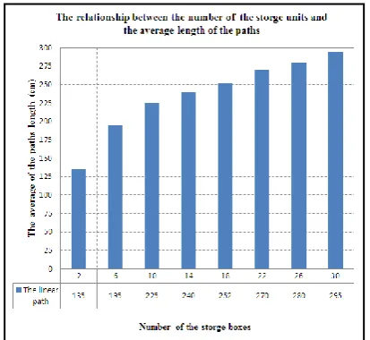
These experiments are used to measure the performance of the linear object store system with respect to the number of store boxes. Fig. 25 shows the relationship between the number of storage boxes and the time of arrival (Sec). The second comparison shows the relationship between the number of storage boxes and the average length of paths (Cm) as shown in Fig. 26. From the first experiment, we found that the time of arrival is increases as the number of store boxes increases. The second experiment shows that the average length of paths is also increases as the number of the store boxes increases.
[image:7.595.327.534.566.742.2]Fig 25: The relationship between the time of arrival and the number of the storage boxes.
Fig 26: The relationship between the average length of the paths and the number of the storage boxes.
6.
CONCLUSION
In this paper the linear object store system is designed and practically constructed in a static environment using line follower robot. This system is tested for both the time of arrival and the average length of the paths with respect to the number of the store boxes. From the experimental results we found the linear object store system produces good performance for both the experiments.
7.
REFERENCES
[1] B. Roddy, S. Markowitz and H. Epelman-Wang, “User Interfaces for Authoring Systems with Object Stores”, IEEE, pp.305-309, 1996.
[2] L. Wu, Q. Zhuge, E. H. Sha, X. Chen, and L. Cheng, "An Efficient Data Distribution Strategy for Object Storage Systems With Hybrid Devices", IEEE, 2017.
[3] M. R. Vasili, S. H. Tang and M. Vasili, “Warehousing in the Global Supply Chain”, pp.159-209.
[4] D. Roy, A. Krishnamurthy, S.S. Heragu and C.J. Malmborg, , Performance analysis and design trade-offs in warehouses with autonomous vehicle technology, IIE
[5] H. Zollinger, "AS/RS application, benefits and justification in comparison to other storage methods: A white paper, Automated Storage Retrieval Systems Production Section of the Material Handling Industry of America, 1999.
[6] H. J. Carlo and I. F. A. Vis, “Sequencing dynamic storage systems with multiple lift and shuttles”, Int. J. Production Economics 140, pp.844–853, 2012.
[7] J. Gagliardi, J. Renaud, and A. Ruiz, “On sequencing policies for unit-load automated storage and retrieval systems”, International Journal of Production Research, vol. 52, pp. 1090-1099, 2014.
[8] A. T. Rashid, F. R. Ali, and O. T. Rashid, “Design and Construction a Dynamic Store System using the Bezier Curve Algorithms”, International Journal of Computer Applications, vol. 179, No. 42, pp. 22-29, 2018. [9] A. T. Rashid, F. R. Ali, and O. T. Rashid, “Software
implementation of a static store system using the digital differential analyzer algorithm”, International Iraqi Conference on Engineering Technology and their Applications, The Islamic University - Najaf – Iraq, 2018.
[10] F. R. Ali, and A. T. Rashid, “Design and implementation of static and dynamic objects store systems using line follower robots”, International Conference on Advances in Sustainable Engineering and Applications, Wasit university - Iraq, 2018.
[11] F. R. Ali, and A. T. Rashid, “Software implementation of objects store system using line follower robots”, Second Al-Sadiq International Conference on Multidisciplinary in IT and Communication Science and Applications, 2017.
[12] P. Goel, G. Arora, and V.K. Panchal, “Incorporating Perception Radius to the Line Follower Robot “, IEEE, 2014.
[13] O. Gumus, M. Topaloglu, and D. Ozcelik, “The use of computer controlled line follower robots in public transport”, 12th International Conference on Application of Fuzzy Systems and Soft Computing, ICAFS, 2016. [14] R. H. Rafi , S. Das, N. Ahmed, I. Hossain, and S. T.
Rezae, " Design & Implementation of a Line Following Robot for Irrigation Based Application", 19th International Conference on Computer and Information Technology, pp. 480-483 , 2016.
[15] Z. Y. Ibrahim , A. T. Rashid, and A. F. Marhoon, " An algorithm for Path planning with polygon obstacles avoidance based on the virtual circle tangents", Iraq J. Electrical and Electronic Engineering, Vol. 12, No. 2, pp. 221-234 , 2016.
[16] Z. Y. Ibrahim , A. T. Rashid, and A. F. Marhoon, " Prediction-Based Path Planning with Obstacle Avoidance in Dynamic Target Environment ", Basrah Journal for Engineering Sciences, Vol. 16, No. 2, pp. 48 – 60, 2017.
[image:8.595.64.271.288.478.2][18] Y. A. Badamasi, "The Working Principle of An Arduino", 11th International Conference on Electronics, Computer and Computation, 2014.
[19] G. Benet, F. Blanes, J.E. Simó and P. Pérez, "Using infrared sensors for distance measurement in mobile robots", Robotics and Autonomous Systems Vol. 40, pp. 255–266, 2002.
[20] H. Juang and K. Lum, “Design and Control of a Two-Wheel Self-Balancing Robot using the Arduino
Microcontroller Board”, 10th IEEE International Conference on Control and Automation (ICCA). Hangzhou, China, 2013.