Control of Induction Motor using Neural Network
B. Gayathri
1, D. Thivya Prasad
21
B. Gayathri M.E., Dept of Electrical & Electronics Engineering, Mount Zion College of Engineering & Technology,
Tamil Nadu, India.
2
D.Thivya Prasad M. Tech., HOD, Dept of Electrical & Electronics Engineering, Mount Zion College of Engineering &
Technology, Tamil Nadu, India.
---***---Abstract — This paper presents The induction machine has proved to be an appropriate solution for most industrial
applications; Moreover, it presents the future of sustainable automotive industry due to the strategies of control and command of which it can be equipped. This paper presents a study of advanced methods applied to the control of induction machine in order to obtain a system satisfying the criterion of robustness. This work has been done as a comparison between the conventional controller and the advanced techniques of control such as fuzzy logic and artificial neural network. The results of various simulation tests highlight the robustness properties of the different control strategies based on orientation of the rotor flux. A relative comparison between the PI controller and the proposed NNM based ANN controller indicates that the ANN mapping controller yields superior performance.
Keywords: GA Genetic Algorithm, IM Induction Motor ANN Artificial Neural Network
1.INTRODUCTION
A high performance induction motor (IM) drive system is characterized by an efficient intelligent speed controller, causing the drive to follow the command speed over a range of varying operating conditions. This tracking of command speed is achieved rapidly and precisely regardless of system parameter variations and sudden load excursions. The conventional PI model is widely used for steady state performance results. For transient performances this model does not yield good results due to saturation effects, parameter variations, load disturbances, temperature variations, etc. The consequence is that these PI controllers typically perform well for limited range of specific conditions. On the other hand, the traditional artificial neural network controllers require extensive off-line training, incur high computation time and rely on the past characteristic behavior of the motor drive for a specific system. However, if the performance is unpredictable, the drive encounters parameters outside the training set. [1-2,5-
6,9-10]. For the saturated IM drive, an improved ANN mapping model is needed to develop a nonlinear polynomial types PI with more parameters that can give a complex map and provide better fit to responses.
To train a controller based on the integrated squared difference over a set period of time, it is preferable to develop a desired model and train it before uploading the controller to the actual system. For online training it would be best to select the most sensitive parameters based on simulation and adjust only those parameters step by step in time. With fixed weights and biases, these would seem to produce control which is proportional-like and integral type, respectively. However, due to the speed-error based self-tuning of the ANN and the interconnections between layers, the drive, when in closed- loop, will seek command speed even if one of the input weights is fixed. This occurs because the non-fixed weights and biases of any interconnections and neurons remain adaptive and will be continually adjusted as long as speed error exists within limits, if the ANN output command torque differs from the reference torque command. The more complex the network, the less appropriate such a comparison to PI-based control becomes. A network consisting of two neurons is compared to a precise and adaptive PI controller which continually adjusts itself in real-time based on speed error and by comparison to reference torque command.
machine and return it to a linear control similar to that of a continuous current machine with a separated excitation.
For the realization of the vector control, there are two methods: the direct method and the indirect method. This study is based on the indirect one; it uses the position of the rotor flux and it requires the use of a speed sensor.
The equations of tensions, fluxes rotor and the electromagnetic torque in a frame of reference (d, q) turning at a speed ω in comparison with the stator are:
Where
(Vrd,Vrq): rotor voltage
(φrd,φrq): Rotor flux
(Ird, Irq): Current rotor
(Isd, Isq): Current stator
ωr: Rotor pulsation
ωs: Stator pulsation
Rr, Lr: Rotor and inductance resistance
P: pole pairs
M: Mutuale inductance
The axis mark (d, q) is oriented along the axis carrying the vector of the rotor flux so we have
Where
Tr: Rotor time constant
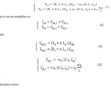
The decoupling by compensation is intended to decouple the axes d and q. This decoupling makes it possible to write the equations of the machine and of the regulation part in a simple manner and thus easily calculate the coefficients of the regulators. The expression of the stator voltages in the Laplace form are given as:
And it can be simplifies to:
With:
Where
LS: Inductance stator
S: Laplace operator
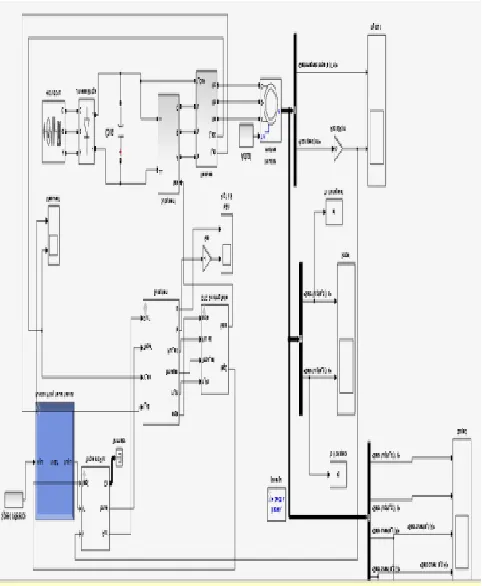
[image:3.596.64.434.184.479.2]The system studied in this work is composed of three PI controllers, which one is for speed regulation and the two others for currents regulation (Is d, Is q). The Figure (1) shows the loop control of current stator during the d axis and the speed control loop is shown on the figure (2).
[image:3.596.205.399.543.755.2]The parameters were calculated by the method of poles compensation the speed control of the indirect vector controller in Fig. 1 is performed using a Proportional-Integral (PI) regulator. The output of the speed controller is the reference torque to the motor. The reference torque is transferred into the inner current control loop. However, while designing the outer speed loop, the inner current control loop can be treated as, With KP and Ki represent respectively the proportional and the integral gain. The parameters were calculated by the method of poles compensation .
2. VECTOR CONTROL BASED ON A FUZZY CONTROLLER
The basic principle of a fuzzy controller approaches the human approach in the sense that the treated variables are not logical in the sense of binary logic (for example) but linguistic variables. Moreover these linguistic variables are processed using rules that refer to certain knowledge of the system behavior.
The design of a fuzzy logic controller starts by assigning the input and output variables. The speed error reference value and its time variation has been selected as the inputs and the electromagnetic torque as the output.
2.1a.Fuzzification and Database Preparation
The step of fuzzification is concerned with the processing of digital values to a fuzzy input values using the databases.
The fuzzification must be made a priority. The universe of discourse of all the input and output variables are established as (- 1, +1). The suitable scaling factors are chosen to brought the input and output variables to this universe of discourse.
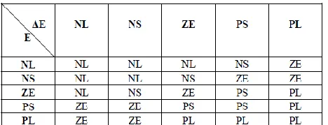
[image:4.596.166.420.425.570.2]In this study each universe of discourse is divided into five overlapping fuzzy sets: NL (Negative Large), NS (Negative Small), ZE (Zero), PS (Positive Small) and PL (Positive Large). For the choice of the membership functions form, the triangular one has been chosen for all the membership functions with the exception of the extremities of each function whose trapezoidal forms used .The table 1 shows the distribution of the fuzzy sets for speed regulation.
TABLE I. DISTRIBUTION OF FUZZY SETS FOR THE SPEED REGULATION
2.1b. Rule Base and Inference Matrix
For the inference method, there are too many methods, and the most applied is the Max-min method, the inference matrix of the fuzzy controller is given in the Table 2.
[image:4.596.182.416.668.758.2]2.1c.Defuzzification: When the fuzzy outputs are computed, they must be transformed into a numerical value. There are several methods of defuzzification, and in this study the method used is the center of gravity.
3. CONTROL OF ASYNCHRONOUS MACHINE USING THE ARTIFICIAL NEURAL NETWORK
A neural network is composed of several simple elements called neurons working in parallel. By adjusting the values of the connections (or weights) between the elements (neurons), we can train a neural network for a specific task. The ANN are used in many important engineering and scientific applications, some of these are: signal enhancement, noise cancellation, pattern classification, system identification, prediction, and control.
[image:5.596.178.419.127.420.2]representation and the approach based on the combination of the genetic algorithm in its real representation and the artificial neural network with a polynomial activation function and it’s based in this study on the last approach. After identifying system’s model to monitor, we train a neural network in order to make system.
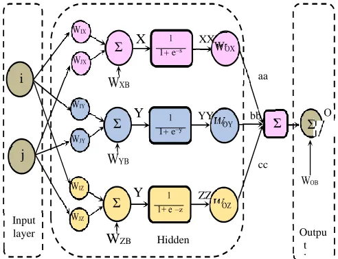
Fig 4.Block Diagram of Neural Network
3. 1.ANN Structure
The amount of nodes in the input layer depends on the number of inputs to the ANN. Since the aim of using the ANN in this application is to mimic the PI controller, the number of nodes required in the input layer is two (i.e. i and j); where one is used to represent proportional gain, and the other is used to represent integral gain. The number of hidden layers,
And the number of neurons in the hidden layer(s) were chosen with the goal of achieving the optimal balance between drive performance and computational complexity. The ANN is command torque, requiring only one neuron in the output layer. Fig. 3 shows the ANN structure based speed drive for the field oriented control of IM. This type of structure was chosen because it is the standard one which allows the creation of the controller with dead band and saturation effect in one input direction and saturation in the other direction.
4. SIMULATION RESULTS AND DISCUSSION
To validate the efficiency of the ANN based speed controller for the IM drive, hysteresis PWM control algorithms are generated. The aim of using ANN is to create a suitable map. This map has to have more degrees of freedom and a more local character. To train a controller based on the integrated squared difference over a set period of time, it is preferable to develop a model of the system and train it before uploading the controller to the actual system. For online training it is best to select the most sensitive parameters based on simulation and adjust only those parameters step by step in time. However, the ANN controller map must be able to mimic the conventional there is no change in its parameters. From these results, it is clear that the ANN controller has been successfully tuned, via the off-line PI-referenced method presented in this paper, to exhibit performances equal to those obtained with the conventional PI controller upon which it is based. The
Σ X 1+ e–s
XX
i aa
Σ Y 1+ e–y
YY bb
Σ Σ
j
cc
Σ Y
Input layer
ZZ
WZB Hidden
layer
results highlight that under the conditions presented here, the ANN controller is, in fact, producing control signals in agreement with the reference PI controller.
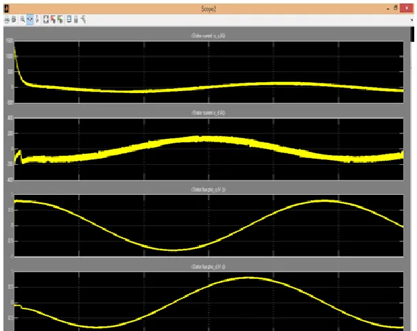
Fig.5: Simulated response of the ANN maps controller-based IM to step changes of command speed with applying rated load.
Fig. 6: Simulated response of the PI controller-
5. EXPERIMENTAL RESULTS AND DISCUSSION
[image:7.596.170.426.414.595.2]6. CONCLUSIONS
The asynchronous machine is a nonlinear system affected by parameters variation and unknown disturbances .This paper deals with a contribution to induction machine’s intelligent control. The work was done in the form of a comparative study between conventional controller and intelligent controllers; it reveals the motivation to realize researches in the field of control by artificial intelligence techniques to the asynchronous machine drive.
It is concluded that the neural controller had a good performances face to parametric variations and to un known disturbances comparing to the other techniques of control, that it can be applied for the electric vehicle motorization and auto mation. It is advisable to examine experimentally the efficiency of neural controller performances to confirm the results found by this study.
REFERENCES
(1). Ashutosh Mishra, Prashant Choudhary, ”Artificial Neural Based Controller for Speed Control of an Induction Motor using Indirect Vector Control Method”, Vol.2, No.4, December 2012, pp. 402~408, Chhattisgarh, Bhili – India.
(2). Kendar Pratap, Shelja, “Artificial neural network (ANN) inspired from biological nervous system”, International Journal of Application or Innovation in Engineering & Management (IJAIEM), Volume 2, Issue 1, India January 2013.
(3). Math Works, Neural Networks Toolbox User's Guide, Math Works, Natick, Mass, USA, 2015.