also to operate them in different modes from any remote places. Our main focus is to operate the home appliances in our desired modes and control them in an easy way. We have developed an android based application for controlling appliances and operate them in different modes like optimum, sleeping, auto etc. also all the appliances can be controlled individually. Different sensors have been used for analyzing lights, temperature and motion. Based on sensor values our algorithm will operate all the appliances according to modes. So by operating them in different modes it will save power as well as make our life easier and comfortable.
Introduction
Home automation makes a home smarter. Smart home is the term which has huge demand in present world and huge possibilities in near future. A home automation system may control lights, temperature, climate, entertainment and many other appliances. Home security is also a part of automation which includes security control and alarm system. Security control means controlling entries based on facial recognition and let recognized people in. On the other hand security alarms could be for fire or security breach in the home and notifying the owners. Home automation typically controls all the appliances from a central hub. The end user interface may vary based on application. The control system could be wall mounted, computers, a mobile phone application or web interface. It actually depends on the developers and the users. In our proposed system we have used mobile phone android application based control system.
Internet of Things allows us to control connected devices from anywhere and exchange data over the devices. Home automation system controls home appliances automatically and when this system is connected to internet it becomes a part of IoT. There are three main generations of home automation. First is, different wireless technology with proxy servers, second is Artificial Intelligence (AI) controlled home automation and lastly robots which directly communicate with humans [2]. This system is first generation automation. For implementing the first generation of the home automation appliances needs to connect with internet so users can control the system from any remote place. That’s why IoT has become a need for automation. This system provide a real life home automation solution which can be implemented at home and need not to be tensed about controlling. This system also provide Android based control system which is more user friendly than web pages. Also this system provide different modes which reduce power consumption
Hardware:
I) Arduino Mega 2560
Figure 1 Arduino Mega 2560
The ATmega2560 provides four hardware UARTs for TTL (5V) serial communication. The channel creates through USB and a virtual com port to Arduino IDE on the computer. To run the code operating system like Windows need an .inf file and for other operating system machine will recognize the board as a COM port automatically. The Arduino software includes a serial monitor which allows simple textual data to be sent to and from the board. The RX and TX LEDs on the board will flash when data is being transmitted via the ATmega8U2 chip and USB connection to the computer (but not for serial communication on pins 0 and 1).
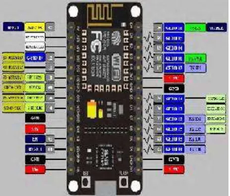
II) NodeMCU
There are various platforms for IoT system one of them is NodeMCU. It provides lower level control on devices which is known as firmware. These control runs on ESP8266 Fi SoC, which hardware is based on ESP-12 module.Esp8266 is a Wi-Fi based communication system’s microchip. It uses TCP/IP protocol for communicating with internet through router. It uses 802.11b/g/n slandered technology for Wi-Fi communication. It is a Tensilica L106 32-bit RISC instruction unite microprocessor with 32 KB instruction RAM, 32KB instruction Cache RAM, 80KB Data memory.ESP8266 (Pin) and Arduino Mega’s (Pin) common pins are GND TX (0)-3.3V, RX (0), 3.3V. For running the ESP8266 on Arduino platform we need to install ESP8266 package in Arduino IDE. As a board is using, we need to give the additional board manager.
As shown in Fig 2 it has 12 GPIO pins. One ADC pin. For this project 7 GPIO pins have been used. They are D0 to D6 which delivers digital outputs.
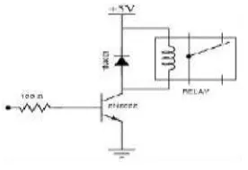
[image:2.612.192.424.506.704.2]Figure 3 Circuit Design of a relay
Maximum range of 4 channel relay board is for DC level 30V and 10A and AC level 250V and 10A. It uses opto-coupler for high voltage safety and prevents ground loop with microcontroller. VCC and RY - VCC are also the power supply of the relay module. In case of driving a large power load, the jumper cap off is taken off and an extra power to RY-VCC is connected to supply of the relay. Connect VCC to 5V of the MCU board to supply input signals. Pins of 4 channel relay are VCC for power supply 5V, gnd for Ground, in1,in2,in3, in4 all are signal controlled pin and connected individually with Arduino ports. And COM is a common pin which is normally grounded unless using for HIGH Voltage. NO is for open connection and NC for closed connection.
Figure 4: 4 Channel Relay Board
IV) LDR:
LDR means Light Dependent Register constructed with two Cadmium Sulphide Photoconductive cells with spectral response which is similar to human eye. With the change of density of light it reacts. The range of LDR is 1000lux to 10 lux. It has no polarity as a result it can be fit in the breadboard easily. As shown in Fig 3.5 both the legs are equal.
V) PIR
[image:3.612.206.413.408.576.2]
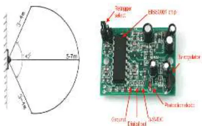
Figure5: (a) Range of PIR Sensor (b) PIR board
As shown in Fig 5(b) it has three pins having spacing of 0.1” where one is used for VCC, the middle one is for driving output voltage which is at least 3.3V TTL output or open collector output. Besides all of these it has two adjustment trimpot for adjusting sensitivity with the environment. They are Delay time adjustment and Distance Adjustment. Clock cycle is used for adjusting the sensitivity. PIR sensor is associated with two timeouts, one of them is TX for calculating the time after detecting movement how long the LED will lit and another one is Ti for calculating the time when will the LED will off when there will be no movement.
VI) DHT22:
[image:4.612.198.400.96.222.2]DHT22 temperature and humidity sensors are very basic and slow, but are great for hobbyists who want to do some basic data logging. The DHT sensors are made of two parts, a capacitive humidity sensor and a thermistor. There is also a very basic chip inside that does some analog to digital conversion and spits out a digital signal with the temperature and humidity.
Figure 6: DHT22 temperature and humidity sensor
It has the following features:
1. Low cost
2. 3 to 5V power and I/O
3. 2.5mA max current use during conversion (while requesting data)
4. Good for 0-100% humidity readings with 2-5% accuracy
5. Good for -40 to 125°C temperature readings ±0.5°C accuracy
II) System Architecture:
[image:5.612.153.463.317.508.2]As shown in Fig 7 user controls the modes and appliances by an android based device through our application. User command is transmitted from device via internet. The esp8266 NodeMCU than receives the command from internet via Wi-Fi. The NodeMCU than passes the command to the controller board arduino mega 2560. Arduino than executes the commanded operation. So android app is for end users to give input. Esp8266 NodeMCU and arduino mega is the control unit of the system. The arduino takes input from the esp8266 for executing actions. For execution of the action arduino also takes inputs from the sensors. Lastly the arduino runs the appliances according to user desired command.
Figure 7 Architecture of the proposed system
III) Android Application:
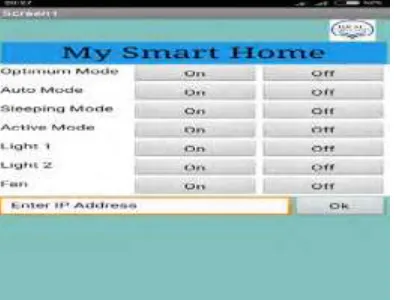
[image:5.612.211.408.561.711.2]An android based application made to fulfill the purpose of our system. It is for the end user to control the system. User can control everything of the system by android app. User can also set modes from the application. As shown in Fig 3.2 it has 14 buttons to control different appliances and modes. The first 8 buttons are for turning on or off optimum, auto, sleeping and activate mode. The last 6 buttons are for controlling individual lights and fan. There is another text box for entering ip address. As our esp8266 module generates dynamic ip addresses after connecting new networks or after reset of previous connection. The user interface of the application is very interactive and very user friendly. User can turn any button on by pressing the on button and which will give command the system to proceed on the command. We have developed this application by using the MIT app inventor 2. MIT app inventor 2 is an open platform for developers to develop useful android based application. In MIT app inventor 2 the back-end operations are designed by block coding. Block codes are easier to design algorithms.
Power Saving Mode:
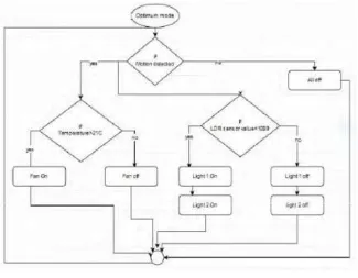
[image:6.612.144.469.343.596.2]I) Optimum Mode: Optimum is the most power saving mode among all. The algorithm of this mode is, first it will activate after getting motion from the motion sensor. Then, based on temperature and light intensity from the temperature and ldr sensors appliances will activate. Condition for turning on fan is temperature must be greater than 21 degrees celsius. As shown in Fig 9 for turning on the lights ldr sensor value must be less than 1000. Otherwise both appliances will be turned off. This is an automatic process where users do not need to bother about controlling. Moreover this mode is saving power consumption by deactivating every appliance when there is no motion detected. So if no one is 16 in room every appliances will remain in off condition. Than if someone enters in room all appliances will activate and execute according to sensor values.
Figure 9 Flow chart of optimum mode
Figure 10 Flow chart of auto mode
Just activate the auto mode and relax. Once the mode is on than it does not change its mode until user changes it. Once auto mode is activated than if the application goes offline it does not change its state of mode or functionality. It will continue running on this mode.
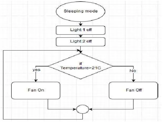
III) Sleeping Mode: This mode is designed for sleeping time. The features of this mode is it will turn off all the lights and make the room dark so that users can sleep without any disturbance of light. The other feature is fan controlling. It will also control fan based on temperature. As shown in Fig11, here the algorithm of fan is designed in a way, it will be turned on if the temperature rises above the threshold value.
[image:7.612.152.462.457.691.2]The threshold temperature we have set is 21 degrees Celsius. So if temperatures goes above the threshold fan will be turned on and again if temperature goes down of threshold temperature fan will be turned off. This mode is comfortable and reliable to run in the time of sleeping.
[image:8.612.226.386.155.333.2]IV) Active Mode:
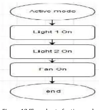
Figure 12 Flow chart of active mode
Active mood is designed for turning on and off the appliances at the same time. Activating this mood will turn on all the appliances and do not change its state until the mode is deactivated. So this mode is for very busy environment where users want to activate all the fans and lights at the same time. The algorithm of this mode is very simple. As shown in fig 12 when the mode is activated all the appliances are instructed to turn on. On the other hand if this mode is off it is instructed to turn off all the appliances.
Result:
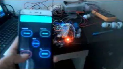
I) Implementation of Home Automation: In the implementation process firstly, we have tested the home automation part. For home automation we have used all our sensors as input, arduino mega as the controller and lights as appliances or output. In this process optimum and auto modes are tested separately. We have checked weather the conditions for turning on fan and lights work properly or not, as shown in Fig 5.1. After succeeding this part we moved into the next phase which is controlling over internet.
Figure 13: Implementation of home automation
[image:8.612.199.414.509.663.2]Figure 14: Controlling from blynk app
Conclusion
In our model a high percentage of accuracy has been achieved though implementation. This system is capable controlling the home appliances based on user’s desired mode. All the modes work with a good accuracy which was found during implementation. Users only need to select modes from their smart phones and our system will do the rest of controlling the appliances. This proposed project is highly reliable. So it can be said that this system has higher accuracy with great efficiency.
References
[1] Nordrum, A. (2016, August 18). Popular Internet of Things Forecast of 50 Billion Devices by 2020 Is Outdated. Retrieved April 14, 2018
[2] Li, R. Y., Li, H. C., Mak, C. K., & Tang, T. B. (2016). Sustainable Smart Home and Home Automation: Big Data Analytics Approach. International Journal of Smart Home,10(8), 177-198. doi:10.14257/ijsh.2016.10.8.18
[3] Reddy, P. S., Reddy, K. T., Reddy, P. A., Ramaiah, G. N., & Kishor, S. N. (2016). An IoT based home automation using android application. 2016 International Conference on Signal Processing, Communication, Power and Embedded System (SCOPES). doi:10.1109/scopes.2016.7955836
[4] Rahman, M. S., Masud, S., Sultana, S., & Bari, M. R. (2017). Web based electric home appliance controller and monitoring system. 2017 IEEE 8th Annual Ubiquitous Computing, Electronics and Mobile Communication Conference (UEMCON). doi:10.1109/uemcon.2017.8248983
[5] Park, H., Jung, E., Lee, W., Lee, H., & Lee, Y. (2017). Network assistance platform for saving power consumption of IoT devices and set-top boxes. 2017 IEEE International Conference on Consumer Electronics (ICCE). doi:10.1109/icce.2017.7889335
[6] NODEMCU ESP8266 CP2102 WIFI MODULE IOT. (n.d.). Retrieved April 14, 2018, from http://www.ifuturetech.org/product/amica-nodemcu- esp8266-lua-cp2102-wifi-development-module-iot- ifuture-baroda-vadodara-gujarat-india/
[8] LDR(Small). (n.d.). Retrieved April 14, 2018, from https://www.cytron.io/p-sn-ldr-s
[9] PIR Motion Sensor. (n.d.). Retrieved April 14, 2018, from https://learn.adafruit.com/pir-passive- infrared-proximity-motion-sensor?view=all
[10]DHT22 AM2302. (n.d.). Retrieved April 14, 2018, from http://www.robotop.lv/en/temperaturnye- humidyty-pressure/467-dht22-am2302.html