A Study on Anchoring Ability of Three-Leg Micro
Intestinal Robot
Wei Lin, Guozheng Yan
The Institute of Medical Precision Engineering and Intelligent System, Shanghai Jiao Tong University, Shanghai, China Email: [email protected]
Received May 23,2012; revised June 22, 2012; accepted July 10, 2012
ABSTRACT
This paper proposes an anchoring and extending micro intestinal robot for medical inspection and surgery propose. The three-leg anchoring method is discussed in detail, and micro robot phantom model is used to test anchoring related pa-rameters for mechanical design. A prototype is designed and fabricated base on the experiment results and is tested in in-vitro experiment. The prototype is locomotive in a pig small intestine under a diameter limitation.
Keywords: Intestinal Tract; Micro Robot; Anchoring Extending
1. Introduction
Noninvasive surgical is an ideal solution for gastrointes-tinal (GI) tract disease since GI tract is a natural open lumen. Intestinal micro robot is a novel ideal to conduct noninvasive surgery. The micro robot can be self-pro- pelled in GI tract with compact size. It is normally de-signed to carry micro video capture unit, drug deposit unit and biopsy forceps. The micro robot can fast travel through the GI tract to search for lesions by video cap-ture unit. The video can transmit in real time, so the di-agnose workstation can receive the signal and notify surgeons. The surgeons can operate a drug release or sample the pathological tissues.
Many prototypes have been carried out to realize this ideal solution, but effective and safety locomotion has not been achieved. Multi-segment, worm-like micro ro-bot [1,2] was proposed by L. M. Lin. It is driven by fric-tion between the inner intestinal tract wall and the robot shell. An eight-legged capsule robot [3,4] was designed and tested by M. Quirini. Its leg motion is driven by mi-cro direct current motors. A padding-based robot [5,6] was introduced by S. Park and was tested by H. M. Kim. This robot can unfold and maneuver six paddles for self-propulsion. Similarly, Y. Zhang introduced a diame-ter-variable capsule robot [7] driven by an external rotat-ing magnetic field. A hybrid locomotive capsule [8], which is driven by both outside magnetic field and robot leg, was tested by M. Simi. Although many efforts have been made to meet the requirements of intestinal tract locomotion, an ideal solution has not yet been obtained in all in vivo trials. The biomechanical features mostly rely on the smooth muscles of the muscularis externa
layer. Various experiments [9-13] have attempted to model the passive behavior of the intestinal walls and the friction between the intestinal walls and contents. Due to the complexity of the responses under mechanical stimu-lation, no model has been able to perfectly demonstrate the mechanical interaction needed for traveling through the small bowel.
This paper proposes a micro robot that can propel it-self through the small bowel by anchoring and extending. The gait of the micro robot is introduced according to biomechanical features of the small bowel. The locomo-tion condilocomo-tion is discussed and relative parameters are tested by a phantom model. In order to be performed in vitro experiment, a prototype of the micro robot is de-signed and fabricated.
2. Locomotion Analyze
A model of an anchoring and extending micro robot is illustrated in this section. The anchoring motion provides alternative friction for two segments whereas the ex-tending motion pushes or drags the two segments.
Figure 1. The gait of micro-robot.
by unfolding its front cabin (Figure 1(d)), folding its rear cabin (Figure 1(e)), and ontracting its middle cabin (Fig- ure 1(f)), the robot completes a forward contraction. By following the above motion sequence, the robot takes a forward step, and by reversing the above sequence, the robot travels backward.
The extending and contracting condition of the robot is show in Figure 2. In the extending stage, the front cabin is pushed by the extending mechanism with thrust force
FPush. Friction force between the front cabin and
intesti-nal wall is fFront, and the resistance at the end of the front
cabin is FResis. The condition of the front cabin moving
forward is
Push Front Resis
F f F (1)
The rear cabin is pushed by mutual force of FPush. The
unfolded anchoring mechanism provides friction fRear,
and the resistance at the end of the rear cabin is FResis .
The condition of the rear cabin staying in relative rest is
Push Rear Resis
F f F (2)
In the contraction stage, the front cabin drags the rear cabin by force FDrag and holds its position by the
un-folded anchoring mechanism with friction fFront . The
condition of the front cabin staying in relative rest is
Drag Front
F f (3) The friction between the rear cabin and intestinal wall is fRear , so the condition of the rear cabin moving
for-ward is
Drag Rear
F f (4) The requirements for mechanism design can be de-duced from (1) to (4). The first requirement is that the push or drag force should be large enough to overcome the friction or resistance but should not be larger than the maximum anchoring force that is provided by the mo-tionless cabin. The second is that the difference in the amount of friction between the folding and unfolding of the anchoring mechanism should be as large as possible.
Push
F FResis fRear fFrontfResis FPush
Rear
f FDrag FDrag fFront
Figure 2. The extending and contracting condition of the ro- bot.
3. Experiment and Result
To verify the comprehensive effect of the resistant and friction force, which supports the micro robot clamping or keeps it sliding, a set of micro robot models is used in
in vitro experiments. In the first set of experiments, a micro robot cabin model without lagged is used. The cabin is 40 mm in length and 13 mm in diameter, and moves in the intestinal tract of various diameter to get resistant and friction force tested. The material of the model is ABS. In the second set of experiments, a legged model is used. With its leg length variable, it travels in the intestinal tract of same diameter to get the threshold resistant force tested. In the third set of experiments, various materials are used to cover the same size micro robot cabin models. It travels in the intestinal tract of same diameter to get the friction force tested.
3.1. Test Bench and Specimen Preparation
[image:2.595.339.510.86.223.2]a
b d
f
e g h
c i
Figure 3. Micro robot model test bench. a: Robot model; b: Intestine sample; c: Force gauge; d: Linear stage; e: Linear position sensor; f: Step motor driver: g: Digital multimeter; h: Workstation; i: Digital camera.
listed in Table 1.
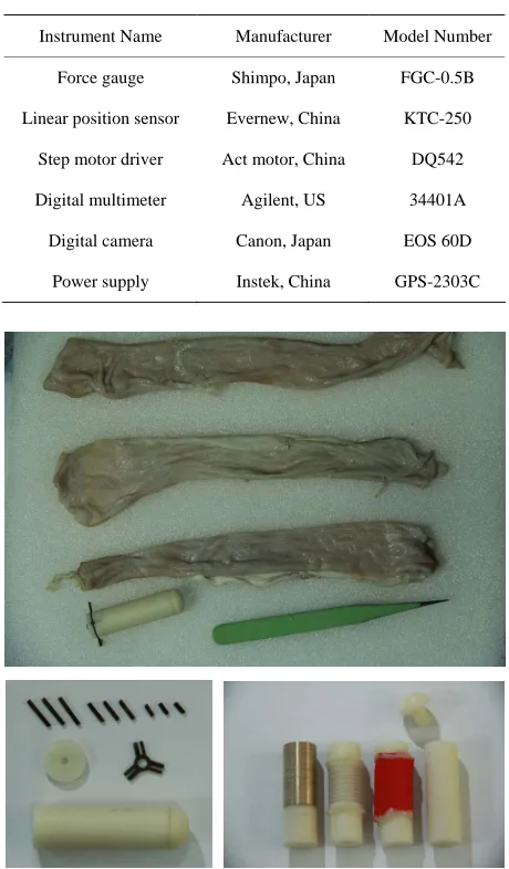
The specimen of the intestinal tract was fetched from a 130 kg male Shanghai White pig. The small intestinal tract was kept in low temperature to resist muscle tone before testing for 5 hours. Three segment of specimen was selected and cut into 20 cm length, with average diameter of 17.2 mm, 19.1 mm and 20.4 mm, respec- tively (see Figure 4 on the top). The specimen was bathed in normal saline to cleanse it of any remaining chyme, and it was exposed to air during the whole testing. The room temperature was controlled in 26˚C.
3.2. Velocity-Tension Test
The linear stage was controlled to cover the velocity range from 0.5 mm/s to 5 mm/s, which is determined by robot extending and contracting speed. The velocity lower than 0.5 mm/s can cause unexpected time consuming while the robot in real intestinal examination, and higher than 5 mm/s can cause patient uncomfortable. The di- ameter of each small intestinal tract specimen varies, so the robot model was replaced in the same spot at the be- ginning of every testing cycle.
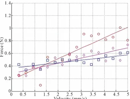
[image:3.595.61.279.85.237.2]This set of experiments was divided into 3 groups. The data from the 17.2 mm, the 19.1 mm and the 20.4 mm diameter intestinal tract were marked as group one, group two and group three, respectively. In group one, when the velocity of the model was as low as 0.3 mm/s, a force of about 0.25 N was used to drag the model in constant speed. The amount of force was doubled when the velocity of model was about 2.5 mm/s, and the amount of force approached 1 N when the velocity was about 5 mm/s. In group two, the test bench used a force of 0.4 N to drag the model traveling at 0.3 mm/s. When the velocity was about 2.0 mm/s, the amount of force was as large as group one. But when reaching the velocity of 5.0 mm/s, the force was about 0.6 N. The same phenomenon happened
Table 1. Main instruments used in test.
Instrument Name Manufacturer Model Number
Force gauge Shimpo, Japan FGC-0.5B
Linear position sensor Evernew, China KTC-250
Step motor driver Act motor, China DQ542
Digital multimeter Agilent, US 34401A
Digital camera Canon, Japan EOS 60D
[image:3.595.308.538.95.488.2]Power supply Instek, China GPS-2303C
Figure 4. Pig small intestine sample used in test (top). Micro robot model with adjustable legs (bottom left). Models used in material-tension test (bottom right).
in group three. The test bench uses force of 0.4 N to drag the model in speed of 0.3 mm/s and 0.6 N for 5 mm/s.
The experiment results show the intestinal tract in large diameter can be easily pass through, and the driver should provide more power to achieve large speed range.
3.3. Leg length-Anchoring Ability Test
the model outline were recorded by a digital camera. Once the relative movement between specimen and model was detected by sight, the applied force stopped increasing and its amount was recorded. The applied force at the moment was defined as threshold resistant force of the anchoring mechanism. After the threshold resistant force was recorded, the applied force was re-moved and the robot model was placed back to the same spot for next test. The measurement of each data point was repeated five times to get an average. When the leg length was 0.5 mm, the threshold was about 0.4 N. This result was similar to the ABS model traveling in the in-testinal tract in lowest velocity. When the leg length was about 5 mm, the threshold was about 0.8 N, and when the out ring of the unfolded robot model approach the di-ameter of specimen, the threshold resistant force was about 0.9 N. The results illustrate the three-leg anchoring model could provide effective anchoring ability.
3.4. Material-Tension Test
In order to test the resistant force of different material coating of the micro robot travelling in the intestinal tract, four different kind of materials are used in the following experiment, i.e. copper, silicon, rubber and ABS (see
Figure 4 on the bottom right). Those models were fabri-cated with ABS core by covering specify materials, in order to reduce mass differences as small as possible. The testing procedure was done the same as the former set of experiments. The amount of the force distributed between 0.9 N to 2 N in the whole velocity range for non-ABS material. The original data and its fit curve are shown in Figure 7.
3.5. Discussion
From the above test, we can deduce the following rules to direct the design of the anchoring and extending micro intestinal robot.
1) According to the first requirement of locomotion condition, the push or drag force should be lower than 1 N, because Figure 6 shows the maximum anchoring force is 1 N; meanwhile, it should be larger than 0.4 N at least to overcome resistant, because Figure 5 shows the resistant force is 0.4 N to drive the robot model move.
2) According to the second requirement of locomotion condition, the robot leg should be as long as possible to get contact with the intestinal tract.
3) According to Figure 7, the area of coating over the micro robot should be as small as possible.
[image:4.595.312.535.85.255.2]4) Because the intestinal tract was prepared to reduce muscle tone, no distinct strain was observed when stress was applied on the intestinal tract. In order to ensure the extending efficiency, the length of the extending step cycle follows K. Wang’s conclusion [14].
[image:4.595.311.536.319.493.2]Figure 5. Model velocity vs. applied force in velocity-tension test. The model is 13 mm in diameter. Red circle for 17.2 mm, magenta diamond for 19.1 mm, blue square for 20.4 mm.
[image:4.595.311.533.528.697.2]Figure 6. Model leg length vs. threshold resistant force.
4. Robot Prototype
The prototype use micro brush direct current motor as driver and each the anchoring and extending mechanism is equipped one motor. The prototype consists of two cabins. The front cabin was equipped with one anchoring mechanism, and the rear cabin was equipped with one anchoring mechanism and one extending mechanism. Two cabins were connected by a universal joint. The ro- bot prototype is showed in Figure 8.
The anchoring mechanism consists of six bars, sepa-rated into three groups and mounted on two nuts with two drive screws parallel to the motor. Each screw is de- signed with two separated threads with an opposite-hand spiral. The two thread segments have the same stroke and lead. Because the two drive screws are mounted on the output stage of the gearbox, the three groups of bars move simultaneously.
The extending mechanism consists of a drive screw and nut pair, which is driven by a speed reducer. The output force is delivered by a moving plate that connects with the nut via bars, and the moving plate is guided by two micro-linear bearings on the rear plate.
The stall force versus the leg-length curve of the an-choring mechanism was tested (see Figure 9). The stall force for each leg is about 0.5 N on average during the entire leg stretching rang. The velocity versus force curve of the extending mechanism was tested (see Figure 10). At rated motor speed, the linear speed of the extending mechanism is 2.35 mm/s, and the output force is about 3.5 N. The speed and force of the extending mechanism can be controlled by pulse-width modulation to meet the requirements of locomotion. The assembled micro robot is 97 mm in length and 13 mm in diameter when its mechanism all folded, and it is about 22 g in weight.
4.1. In-Vitro Experiment
[image:5.595.314.532.86.265.2]To examine the functionality of the micro robot, two types of experimental environments were constructed. A
[image:5.595.311.533.308.481.2]Figure 8. Micro-robot prototype with anchoring actuator folded (top). Anchoring mechanism, parts and assembly (bot- tom left). Extending mechanism assembly (bottom right), (mm).
Figure 9. The relationship between radial displacement and stall force of anchoring mechanism.
Figure 10. Results of force and speed in extending mecha-nism testing.
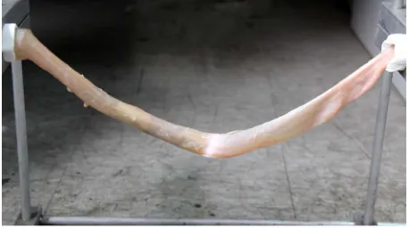
flexible tube was used to stimulate the human small bowel to verify the mechanical characteristics in an ideal environment. A pig small bowel was used to test the lo-comotion in a phantom model because a pig’s small bowel is similar to that of a human in biomechanics and morphology (see Figure 11).
[image:5.595.58.287.559.690.2]Figure 11. In vitro experiment test bench.
4.2. Discussion
Stimulated experiments show the micro robot working properly. The efficiency of locomotion is close to 100% due to no contraction step lost and no legs anchoring slippage. The experiment result demonstrates the micro robot is suitable of locomotion in an ideal small bowel tube.
In vitro phantom experiment shows the robot is not adaptable to small bowel which diameter larger than 20 mm. As the maxim extension of each anchoring leg is 3.5 mm, when an anchoring mechanism unfolded, the small bowel is stretched into a triangle with approximately 18.2 mm on the side, and that is equal to a circle of 17.3 mm in diameter. Each of the three legs in one anchoring mechanism gets fully contract to the small bowel when the diameter less than 18 mm, Equations (1) to (4) are obeyed. Between the diameter of 18 mm and 22 mm, the efficiency of anchoring mechanism is getting lower. When the diameter is lager than 22 mm, the Equations (2) and (3) are break, so the anchoring mechanism lost effec-tiveness.
5. Conclusions
The anchoring and extending model of micro intestinal robot was analyzed and tested, a prototype of this robot was designed and fabricated based on the model, the re-sult of in vitro experiment verify the locomotion of model is effective under a diameter restriction.
To working towards the ideal model for intestinal ex-amination and operation, the relationship between leg number, leg tip pattern, and anchoring ability should be considered to optimize anchoring efficiency, and the vis- coelastic and ruffle of intestinal tract, and the fluid vis- cosity should be modeled to evaluate the mechanical energy lost during locomotion. Furthermore, video cap-ture unit, drug delivery unit and biopsy forceps should be equipped to fulfill surgery requirements.
6. Acknowledgements
This work was supported in part by the 863 program of P.
R. China under Grant 2007AA04Z234, and in part by the National Natural Science Foundation of China under Grant 60875061, 31170968 and 30800235, and in part by Human Spaceflight Research Project of China under Grant 010203, and in part by the Science and Technol-ogy Commission of Shanghai Municipality (P. R. China) under Grant 09DZ1907400.
REFERENCES
[1] L. Lin, L. Gao, G. Yan and R. Rong, “A Study on the Endoscope System Driven by Squirmy Robot,” IEEE In- ternational Conference on Intelligent Processing Systems, Beijing, 28-31 October 1997, pp. 75-81.
[2] K. Wang, G. Yan, P. Jiang and D. Ye, “A Wireless Ro- botic Endoscope for Gastrointestine,” IEEE Transactions on Robotics, Vol. 24, No. 1, 2008, pp. 206-210.
doi:10.1109/TRO.2008.915418
[3] M. Quirini, R. J. Webster, A. Menciassi and P. Dario, “Design of a Pill-Sized 12-Legged Endoscopic Capsule Robot,” IEEE International Conference on Robotics and Automation, Roma, 10-14 April 2007, pp. 1856-1862.
[4] M. Quirini, A. Menciassi, S. Scapellato, et al., “Feasibil- ity Proof of a Legged Locomotion Capsule for the GI Tract,” Gastrointestinal Endoscopy, Vol. 67, No. 7, 2008, pp. 1153-1158. doi:10.1016/j.gie.2007.11.052
[5] S. Park, H. Park, S. Park and B. Kim, “A Paddling Based Locomotive Mechanism for Capsule Endoscopes,” Jour- nal of Mechanical Science and Technology, Vol. 20, No. 7, 2006, pp. 1012-1018. doi:10.1007/BF02916000
[6] H. M. Kim, S. Yang, J. Kim, et al., “Active Locomotion of a Paddling-Based Capsule Endoscope in an in Vitro
and in Vivo Experiment (with Videos),” Gastrointestinal Endoscopy, Vol. 72, No. 2, 2010, pp. 381-387.
doi:10.1016/j.gie.2009.12.058
[7] Y. Zhang, S. Jiang, X. Zhang, H. Yu, D. Wang and D. Guo, “Dynamic Characteristics of an Intestine Capsule Robot with Variable Diameter,” Chinese Science Bulletin, Vol. 55, No. 17, 2010, pp. 1813-1821.
doi:10.1007/s11434-009-3370-6
[8] M. Simi, P. Valdastri, C. Quaglia, A. Menciassi and P. Dario, “Design, Fabrication, and Testing of a Capsule with Hybrid Locomotion for Gastrointestinal Tract Ex- ploration,” IEEE/ASME Transactions on Mechatronics, Vol. 15, No. 2, 2010, pp. 170-180.
[9] D. Dodou, P. Breedveld and P. A. Wieringa, “Stick, Un- stick, Restick Sticky Films in the Colon,” Minimally In- vasive Therapy & Allied Technologies, Vol. 15, No. 5, 2006, pp. 286-295. doi:10.1080/13645700600929144
[10] J. Kwon, E. Cheung, S. Park and M. Sitti, “Friction En- hancement via Micro-Patterned Wet Elastomer Adhesives on Small Intestinal Surfaces,” Biomedical Materials, Vol. 1, No. 4, 2006, p. 216. doi:10.1088/1748-6041/1/4/007 [11] P. Ciarletta, P. Dario, F. Tendick and S. Micera, “Hy-
doi:10.1177/0278364909101190
[12] S. Tognarelli, V. Pensabene, S. Condino, et al., “A Pilot Study on a New Anchoring Mechanism for Surgical Ap- plications Based on Mucoadhesives,” Minimally Invasive Therapy & Allied Technologies, Vol. 20, No. 1, 2011, pp. 3-13. doi:10.3109/13645706.2010.496955
[13] H. Gregersen and G. Kassab, “Biomechanics of the Gas-
trointestinal Tract,” Neurogastroenterology & Motility, Vol. 8, No. 4, 1996, pp. 277-297.
doi:10.1111/j.1365-2982.1996.tb00267.x