NOTICE
and shall not be reproduced without prior written approval of NEC Unified Solutions, Inc.
D
termis a registered trademark of NEC Corporation and Electra Elite is a registered
trademark of NEC America, Inc. Windows is a registered trademark of Microsoft Corporation.
AT&T is a registered trademark of American Telephone and Telegraph Company. Lucent
Technologies is a trademark or service mark of Lucent Technologies Inc. Nortel Networks
and the Nortel Networks logo are trademarks of Nortel Networks.
Copyright 2005
NEC Infrontia, Inc.
6535 N. State Highway 161
Irving, TX 75039-2402
S
ECTION
1
A
BOUT
THIS
MANUAL
The Programming Manual provides the technician with all of the necessary
information for programming the Electra Elite IPK system.
Programming can be accomplished using a PC or a Multiline Terminal.
S
ECTION
2
M
ANUAL
O
RGANIZATION
This manual provides instructions for programming the Electra Elite IPK system.
Chapter 1 – Multiline Terminal Programming
This chapter includes the basic information for programming the system.
Chapter 2 – Memory Blocks
This chapter includes all of the Memory Blocks used to program the system. Detailed
programming instructions are provided for each Memory Block.
Chapter 3 – Advanced Applications
This chapter includes information for code restrictions, Automatic Route Selection
(ARS) and ISDN-PRI Call-by-Call.
Appendices
S
ECTION
3
S
UPPORTING
D
OCUMENTS
A set of manuals for the Electra Elite system provides all the information necessary to
install and support the system. Other manuals included in the set are described
below.
This manual provides detailed information related to every feature available in the
system.
Electra Electra Elite IPK General Description Manual
This manual provides general information about the system features, configuration,
and standards. An overview of the Electra Elite IPK system that is useful when
presenting information to potential customers is provided.
Electra Electra Elite IPK System Hardware Manual
The System Hardware Manual is intended for the system installer and provides
detailed instructions for installing the Electra Elite IPK KSU, ETUs, Multiline
Terminals, and optional equipment.
Electra Electra Elite IPK Least Cost Routing Manual
This manual provides instructions to the service technician for programming the
customer site for least cost routing.
Electra Electra Elite IPK Automatic Call Distribution Manual
This manual provides the service technician with instructions for programming the
ACD. This manual can also be used by the ACD supervisor at the customer site to
become familiar with the ACD/MIS feature.
Electra Electra Elite IPK Job Specifications Manual
This manual provides general information about the Electra Electra Elite IPK ACD
Plus features, installation procedures and feature programming. The NEC Electra
Electra Elite IPK ACD Plus is an Automatic Call Distribution card that supports up to
40 Agents and 12 supervisors at one time.
Electra Electra Elite IPK Wireless System Manual
This manual describes the system and provides hardware installation and
Chapter 1
Multiline Terminal Programming
Section 1
General Information ... 1-1
Section 2
Programming the System ... 1-1
2.1
Features of Programming ... 1-2
2.2
System Programming Modes ... 1-3
2.3
Before Programming ... 1-4
2.3.1
Check Points ... 1-4
2.3.2
Preliminary Points ... 1-4
2.4
Writing System Data ... 1-5
2.5
Programming Methods ... 1-6
2.5.1
Initializing the System ... 1-6
2.5.2
Using the Multiline Terminal for Programming ... 1-6
2.5.3
Entering Programming Mode ... 1-8
2.5.4
Page Switching ... 1-9
2.5.5
Station Port Numbering Plan ... 1-12
Section 3
System Data List ... 1-13
Chapter 2
Memory Blocks
Section 1
Programming System Data Using the Memory Block ... 2-1
1-1-00
Pause Time Selection ...2-2
1-1-01
DP Interdigit Time Selection ...2-3
1-1-02
Hookflash Time Selection ...2-4
1-1-03
Hold Recall Time Selection (Non-Exclusive Hold) ...2-6
1-1-05
Start Time Selection ...2-9
1-1-06
CO/PBX Incoming Ringing Alarm Time Selection ...2-11
1-1-07
Tie Line Delay Ringing Time Selection ...2-13
1-1-09
Manual Pause Selection ...2-16
1-1-11
System Transfer/Camp-On Selection ...2-18
1-1-12
Station Transfer/Camp-On Recall Time Selection ...2-19
1-1-13
CO Transfer Ring Pattern Selection ...2-21
1-1-14
CO Transfer Ring Tone Selection ...2-23
1-1-18
System Speed Dial Restriction by Tenant ...2-24
1-1-20
DID Digit Length Selection ...2-27
1-1-21
DID Digit Conversion Assignment ...2-28
1-1-22
DID Digit Conversion Table ...2-29
1-1-23
DID Forward Station Number for Busy Station or Undefined Digit ...2-31
1-1-24
PBX/CTX Access Code Assignment I ...2-33
1-1-25
PBX/CTX Access Code Assignment II ...2-35
1-1-27
Automatic Day/Night Mode Switching Time Assignment ...2-37
1-1-28
Distinctive Ringing by Telephone or CO Selection ...2-39
1-1-29
Private Line Assignment ...2-40
1-1-30
Route Advance Block Assignment ...2-41
1-1-32
Automatic Day/Night Mode by Day of Week Selection ...2-43
1-1-33
Speed Dial Number/Name Display Selection ...2-45
1-1-34
Tie Line First Ring Pattern Selection ...2-46
1-1-35
Speed Dial Buffer Allocation ...2-48
1-1-37
Trunk Queuing Timeout Selection ...2-49
1-1-46
Access Code (1-Digit) Assignment ...2-51
1-1-47
Access Code (2-Digit) Assignment ...2-58
1-1-48
Access Code (3-Digit) Assignment ...2-60
1-1-49
Networking Trunk Group/Route Advance Assignment ...2-64
1-1-50
CO/PBX Outgoing Digit Add Assignment ...2-65
1-1-51
CO Line Ringing Pattern Selection ...2-67
1-1-52
PBX Line Ringing Pattern Selection ...2-69
1-1-57
CO/PBX Prepause Time Selection ...2-76
1-1-59
Synchronous Ringing Selection ...2-77
1-1-60
8-Digit Matching Table Assignment ...2-78
1-1-61
8-Digit Matching Table to Class Assignment ...2-80
1-1-62
System Speed Dial Override by Class Selection ...2-82
1-1-63
Hold Recall Time Selection (Exclusive) ...2-83
1-1-65
Code Restriction Class Allow/Deny Selection ...2-85
1-1-66
8-Digit Matching Table to Normal Dial Assignment ...2-86
1-1-67
OCC Table Assignment ...2-87
1-1-68
8-Digit Matching Table to OCC Table Assignment ...2-88
1-1-69
Tie Line Code Restriction Assignment ...2-89
1-1-70
Code Restriction Class Assignment When Lockout is Set ...2-90
1-1-71
First Delay Announcement Start Time Selection ...2-91
1-1-72
First Delay Announcement Repeat Selection ...2-92
1-1-73
First to Second Delay Announcement Interval Time Selection ...2-93
1-1-74
Second Delay Announcement Repeat Selection ...2-94
1-1-75
Second Delay Announcement Repeat Interval Time Selection ...2-95
1-1-76
Barge-In Alert Tone Assignment ...2-96
1-1-77
Delayed Ringing Time Assignment (CO) ...2-97
1-1-78
Caller ID Display Assignment for System Mode ...2-98
1-1-79
BGM Port Assignment ...2-99
1-1-80
ISDN DTMF Duration/Interdigit Selection ...2-100
1-1-81
ISDN Dial Interval Time Selection ...2-101
1-1-82
CO Feature Code Service for Code Restriction ...2-103
1-1-86
Call Monitoring Alert Tone Assignment ...2-104
1-2-00
Internal Paging Timeout Selection ...2-105
1-2-01
Intercom Call Voice/Tone Signal Selection ...2-107
1-2-02
Automatic Callback Release Time Selection ...2-108
1-2-03
2~7-Digit Station Number Selection ...2-110
1-2-08
Specified Station Access Code Assignment ...2-114
1-2-09~18 Customized Message 1~10 Assignment ...2-116
1-2-19
Intercom Ring Pattern Selection ...2-117
1-2-20
Intercom Ring Tone Selection ...2-119
1-2-21
PS Telephone Block Assignment ...2-120
1-2-22
Call Forward - No Answer Time Selection ...2-122
1-2-23
System Call Park Recall Time Selection ...2-124
1-2-24
Intercom Feature Access Code Assignment ...2-126
1-2-25
Internal Paging Alert Tone Selection ...2-128
1-2-26
Delayed Ringing Time Assignment (ICM) ...2-129
1-2-30
PS Out of Area Time Assignment ...2-130
1-2-32
IP Telephone Block Assignment ...2-131
1-2-33
IP Telephone Block Assignment Allow/Deny Selection ...2-133
1-2-34
Expanded Station Number Assignment ...2-135
1-3-01
Bounce Protect Time Selection ...2-137
1-3-02
SLT Hookflash Signal Selection ...2-138
1-3-03
First Digit PBR Release Time Selection ...2-139
1-3-04
Dial 1 (DP) Hookflash Selection ...2-141
1-3-05
Hookflash Start Time Selection ...2-142
1-3-06
Hookflash End Time Selection ...2-143
1-3-07
Voice Mail Digit Add Assignment ...2-144
1-3-08
Voice Mail DTMF Delay Time Selection ...2-145
1-3-09
Voice Mail Disconnect Time Selection ...2-146
1-3-10
Voice Mail DTMF Duration/Interdigit Time Selection ...2-147
1-3-11
SLT/PS II Talk Start Timer ...2-148
1-3-12
SLT/ISDN TELCO Account Codes Allow/Deny Selection ...2-150
1-4-00
Tandem Transfer Automatic Disconnect Time Selection ...2-151
1-4-01
Automated Attendant First Digit PBR Release Time Selection ...2-152
1-4-02
Automated Attendant Transfer Delayed Ringing Time Selections ...2-154
1-4-03
Automated Attendant No Answer Disconnect Time Selection ...2-157
1-4-04
Tandem Transfer SMDR Print Extension Assignment ...2-159
1-4-11
Automated Attendant Message Day/Night Mode Selection ...2-163
1-4-12
Automated Attendant Message to Tenant Assignment ...2-164
1-4-13
Automated Attendant Answer Delay Time Assignment ...2-165
1-4-14
Automated Attendant Message Access Code
(1-Digit) Assignment ...2-166
1-4-15
Automated Attendant Message Access Code
(2-Digit) Assignment ...2-169
1-4-16
Automated Attendant Message Repeat Selection ...2-170
1-4-17
Automated Attendant Delay Announcement Hold Tone Selection ...2-171
1-4-18
Automated Attendant Delay Announcement Assignment ...2-172
1-4-19
Automated Attendant 1st to 2nd Delay Announcement
Interval Time Selection ...2-173
1-4-20
Automated Attendant Delay Announcement
Disconnect Time Selection ...2-174
1-4-21
Automated Attendant Extension Number Assignment ...2-175
1-4-22
Automated Attendant Direct Extension Ring Assignment ...2-176
1-5-02
SMDR Print Format ...2-177
1-5-13
Printer Connected Selection ...2-178
1-5-14
Printer Line Feed Control Selection ...2-179
1-5-25
SMDR Valid Call Time Assignment ...2-181
1-5-26
SMDR Incoming/Outgoing Print Selection ...2-182
1-6-01
Attendant Add-On Console to Telephone Port Assignment ...2-183
1-6-03
DSS Call Voice/Tone Signal Selection ...2-184
1-6-05
Attendant Add-On Console Key Selection ...2-185
1-6-07
Message Board Lamp Assignment ...2-188
1-6-08
Attendant Transfer Selection During Live Record ...2-189
1-7-00
Doorphone Assignment ...2-191
1-7-01
Doorphone Display Time Selection ...2-192
1-7-02
External Speaker Connection Selection ...2-194
1-7-03
External Paging Alert Tone Selection ...2-195
1-7-06
External Paging Timeout Selection ...2-200
1-7-07
External Ring Relay Pattern Selection ...2-202
1-7-08
External Speaker Chime Selection ...2-204
1-7-09
External Speaker Chime Start Time Selection ...2-205
1-8-01
SLT or Automated Attendant/DISA to CPU PBR Selection ...2-207
1-8-02
PBR Receive Level Assignment for Automated Attendant/DISA ...2-208
1-8-04
Time Display (12h/24h) Selection ...2-210
1-8-07
Class of Service (Attendant) Feature Selection 1 ...2-211
1-8-08
Class of Service (Station) Feature Selection 2 ...2-214
1-8-09
Music on Hold Pattern Selection ...2-220
1-8-10
PBR Interdigit Release Time Selection ...2-221
1-8-11
System Refresh Time Assignment ...2-223
1-8-12
VRS Message Recording Time Selection ...2-224
1-8-13
VRS Message Function Assignment ...2-225
1-8-15
Tone Assignment ...2-227
1-8-16
Voice Prompt to Tone Assignment ...2-230
1-8-17
PC Programming Password Assignment ...2-231
1-8-18
Site Name Assignment ...2-232
1-8-25
ACD/UCD Group Agent Assignment ...2-233
1-8-26
Voice Mail Quick Transfer Master Hunt Number ...2-234
1-8-27
Forced Account Code/Authorization Code Length Assignment ...2-236
1-8-29
SCD (Simplified Call Distribution) Pilot Number Assignment ...2-238
1-8-30
SCD Group Agent Assignment ...2-239
1-8-31
Hold Tone Source Assignment ...2-240
1-8-32
Hold Internal Tone Volume Selection ...2-241
1-8-33
Master Clock Selection ...2-242
1-8-35
COM Port Baud Rate Setting Assignment ...2-244
1-8-36
COM Port Parity/Stop Bit Setting Assignment ...2-245
1-8-37
General Purpose Relay Assignment ...2-246
1-8-38
Modem Number For Remote Programming Assignment ...2-247
1-8-40
ACD Hunt Time ...2-248
1-8-46
Enhanced 911 Dialing Digit Assignment ...2-254
1-8-47
Call Arrival Key Voice Mail Message Notification Assignment ...2-255
1-8-48
Automatic Daylight Saving Time Selection ...2-256
1-8-49
New AA-Info Yes/No Selection ...2-257
1-8-51
Call Park Selection ...2-260
1-9-00
DISA ID Code Assignment ...2-261
1-9-02
DISA Password Effect/Invalid Selection ...2-262
1-10-00
Call by Call Type of Network ID Assignment ...2-263
1-10-01
Call by Call ID Plan Assignment ...2-265
1-10-02
Call by Call Type of Number Assignment ...2-267
1-10-03
Call by Call Numbering Plan ID Assignment ...2-269
1-10-04
Call by Call Network ID Assignment ...2-271
1-10-05
Call by Call Facility Coding Value Assignment (Service) ...2-273
1-10-06
Call by Call Facility Coding Value Assignment (Feature) ...2-275
1-10-07
Call by Call Service Parameter Assignment ...2-277
1-10-08
Call by Call Max Digit Assignment ...2-279
1-10-09
Call by Call Simulated Facility Group Assignment ...2-281
1-10-20
Call by Call Outgoing SFG Assignment ...2-283
1-10-21
Call by Call Outgoing/Incoming SFG Assignment ...2-285
1-10-22
Call by Call Incoming Type Selection ...2-287
1-11-00
T1 Signal Format Selection ...2-289
1-11-01
Clear Channel Selection ...2-290
1-11-02
Line Length Selection ...2-291
1-11-03
IP K-CCIS Selection ...2-292
1-11-05
T1 Channel Selection ...2-294
1-11-06
Signaling Selection ...2-296
1-11-07
DTI Trunk Type Assignment ...2-297
1-11-08
Digits Delete for T1 ANI Assignment ...2-299
1-12-00
ACD/UCD Group Pilot Number Assignment ...2-301
1-12-02
ACD/UCD Overflow Time Selection ...2-305
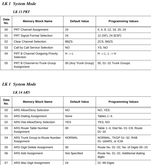
1-13-00
PRT Channel Assignment ...2-307
1-13-01
PRT Signal Format Selection ...2-309
1-13-02
Clear Channel Selection ...2-311
1-13-03
Call by Call Service Selection ...2-312
1-13-04
PRT B Channel Outgoing Priority Selection ...2-313
1-13-05
PRT B Channel-to-Trunk Group Assignment ...2-314
1-14-00
ARS Allow/Deny Selection ...2-317
1-14-01
ARS Dialing Assignment ...2-318
1-14-02
ARS Dial Allow/Deny Selection ...2-320
1-14-03
ARS Route Table Number Assignment ...2-322
1-14-04
ARS Trunk Group to Route Number Assignment ...2-324
1-14-05
ARS Digit Delete Assignment ...2-326
1-14-06
ARS Digit Add Assignment ...2-328
1-14-07
ARS Max Digit Assignment ...2-330
1-15-00
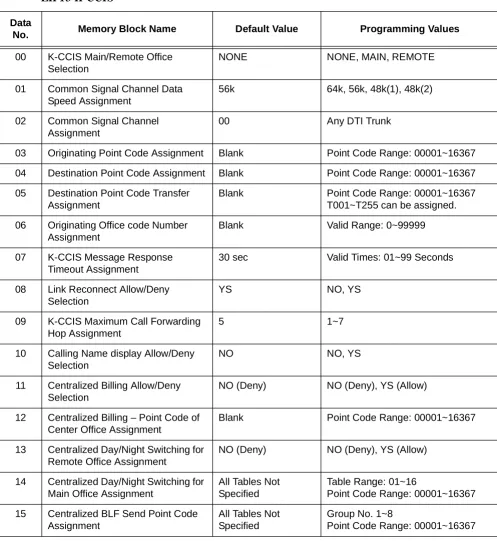
K-CCIS Main/Remote Office Selection ...2-333
1-15-01
Common Signal Channel Data Speed Assignment ...2-335
1-15-02
Common Signal Channel Assignment ...2-337
1-15-03
Originating Point Code Assignment ...2-339
1-15-04
Destination Point Code Assignment ...2-341
1-15-05
Destination Point Code Transfer Assignment ...2-343
1-15-06
Originating Office Code Number Assignment ...2-346
1-15-07
K-CCIS Message Response Timeout Assignment ...2-348
1-15-08
Link Reconnect Allow/Deny Selection ...2-350
1-15-09
K-CCIS Maximum Call Forwarding Hop Assignment ...2-352
1-15-10
Calling Name Display Allow/Deny Selection ...2-354
1-15-11
Centralized Billing Allow/Deny Selection ...2-356
1-15-12
Centralized Billing – Point Code of Center Office Assignment ...2-358
1-15-13
Centralized Day/Night Switching for Remote Office Assignment ...2-360
1-15-14
Centralized Day/Night Switching for Main Office Assignment ...2-362
1-15-15
Centralized BLF Send Point Code Assignment ...2-364
1-15-19
Centralized 911 Allow/Deny Selection ...2-372
1-15-20
Centralized 911/Calling Party (CPN) Originating Number Selection ...2-374
1-15-21
Centralized 911 Look Ahead Routing Allow/ Deny Selection ...2-376
1-16-00
Auto Negotiation Yes/No Selection ...2-379
1-16-01
Port Speed Selection – 10/100 Base-T ...2-381
1-16-02
Port Duplex Mode Selection ...2-383
1-16-03
MDI/MDIX Mode Selection ...2-385
1-16-04
VLAN Mode Selection ...2-387
1-16-05
Default VLAN ID Tag Insertion Assignment ...2-389
1-16-06
Port Based Priority Selection ...2-391
1-16-07
High Priority RX Tag Threshold ...2-393
1-16-08
High Priority TX Tag Assignment ...2-395
1-16-09
Low Priority TX Tag Assignment ...2-397
1-16-10
Port Mirroring Selection ...2-399
1-16-11
Mirroring Source Port Assignment ...2-401
1-16-12
Mirroring Target Port Assignment ...2-403
1-16-13
VLAN Group to VLAN ID Assignment ...2-405
1-16-14
Port VLAN Group Membership ...2-407
1-16-15
VLAN Tag Insertion Selection ...2-409
1-16-16
Flow Control for Full Duplex Selection ...2-411
1-16-17
Back Pressure for Half Duplex ...2-413
2-01
Trunk to Tenant Assignment ...2-415
2-05
Line Key Selection ...2-417
2-06
Line Key Selection for Tenant Mode ...2-418
2-07
System Speed Dial Display Assignment ...2-421
2-08
ECR Relay to Tenant Assignment ...2-423
2-09
DID Limit to Tenant Assignment ...2-424
3-00
Trunk Name/Number Assignment ...2-425
3-02
Trunk Status Selection ...2-426
3-04
Trunk-to-Trunk Transfer Yes/No Selection ...2-428
3-05
Trunk Incoming Answer Mode Selection ...2-430
3-06
Automatic Tandem Trunk Assignment ...2-432
3-07
CO/PBX Ringing Variation Selection ...2-433
3-11
CO External Source Selection ...2-434
3-12
Trunk-to-MOH Trunk Assignment ...2-435
3-14
Tie Line Type Assignment ...2-436
3-15
Trunk DTMF Duration/Interdigit Selection ...2-438
3-16
Tie Line Prepause Time Selection ...2-440
3-17
Tie Line Answer Detect Time Selection ...2-441
3-18
Tie Line Release Detect Time Selection ...2-442
3-19
Tie Line/CO/PBX Incoming Signal Detect Time Selection ...2-444
3-20
Tie Line Loop Off-Guard Time Selection ...2-446
3-21
Tie Line Length of Wink Signal Selection ...2-448
3-22
Tie Line Length of Delay Signal Selection ...2-450
3-24
Tie Line Incoming Interdigit Timeout Selection ...2-452
3-25
Tie Line Wink/Delay Signal Detect Timeout Selection ...2-454
3-27
Tie Line Dial Tone Selection ...2-456
3-28
Tie Line Reorder Tone Selection ...2-457
3-29
Trunk Internal Transmit Pad Selection ...2-459
3-30
Trunk Internal Receive Pad Selection ...2-461
3-31
Trunk External Transmit Pad Selection ...2-463
3-32
Trunk External Receive Pad Selection ...2-465
3-33
Disconnect Recognition Time Selection ...2-467
3-38
Automated Attendant Message to Trunk Selection ...2-468
3-40
Automatic Release Signal Detection Selection ...2-469
3-41
Delay Announcement Assignment ...2-470
3-42
DIT Assignment ...2-471
3-43
ANA Assignment ...2-473
3-44
Caller ID Display Assignment for CO/PBX Line ...2-475
3-45
Live Record Trunk Selection ...2-477
3-59
Automated Attendant Function Selection ...2-481
3-61
DIT/ANA Delay Answer Time Selection ...2-482
3-62
DIT Tenant Assignment ...2-484
3-63
DIT Weekend Mode Selection ...2-485
3-64
DIT Night Mode Delay Answer Selection ...2-486
3-65
Hold Tone Automated Attendant Selection ...2-487
3-67
CO/PBX Ringing Pattern Selection ...2-489
3-69
911 – Cut Through Trunk Selection ...2-491
3-70
CIC Number Assignment ...2-493
3-73
CO Message Waiting Yes/No Selection ...2-495
3-77
ISDN-BRI/PRI Directory Number Checking Selection ...2-496
3-90
Polarity Reverse Selection ...2-498
3-91
Trunk Type Selection ...2-499
3-92
Trunk (Installed, DP/DTMF) Selection ...2-500
4-01
CO/PBX Ring Assignment (Day Mode) ...2-501
4-02
CO/PBX Ring Assignment (Night Mode) ...2-503
4-03
Doorphone Chime Assignment (Day Mode) ...2-505
4-04
Doorphone Chime Assignment (Night Mode) ...2-507
4-07
Code Restriction Class Assignment (Day Mode) ...2-509
4-08
Code Restriction Class Assignment (Night Mode) ...2-510
4-09
Telephone to Tenant Assignment ...2-511
4-10
Station Number Assignment ...2-513
4-11
Ringing Line Preference Selection ...2-515
4-12
Line Key Selection for Telephone Mode ...2-517
4-13
CO/PBX Busy Forward Station Assignment ...2-520
4-14
Intercom Master Hunt Number Selection ...2-521
4-15
Intercom Master Hunt Number Forward Assignment ...2-523
4-17
Station to Class of Service Feature Assignment ...2-526
4-18
Station Name Assignment ...2-528
4-23
Prime Line/Hot Line Assignment ...2-532
4-24
SLT Hookflash Assignment ...2-534
4-26
DISA ID Number Station Assignment ...2-536
4-28
Multilingual LCD Indication Selection ...2-537
4-29
HFU Selection ...2-538
4-30
Hold/Transfer Recall Display Selection ...2-539
4-31
Receiving Internal/All Call Page Selection ...2-540
4-32
Trunk Digit Restriction ...2-541
4-35
Voice Mail/SLT Selection ...2-542
4-36
Voice Prompt Selection ...2-544
4-37
Extension Line Key Ring Assignment (Day Mode) ...2-545
4-38
Extension Line Key Ring Assignment (Night Mode) ...2-547
4-39
APR Ring Mode Assignment ...2-549
4-40
LCR Class Selection ...2-551
4-41
SIE/CAR Ringing Line Preference Selection ...2-553
4-42
Call Forward-Busy Immediately/Delay Selection ...2-555
4-43
Station to Call Appearance Block Assignment ...2-557
4-44
Caller ID Preset Dial Outgoing CO Selection ...2-558
4-46
Live Record Auto Delete Selection ...2-559
4-47
ISDN Directory Number Selection ...2-560
4-49
Caller ID Display for CAR Key Assignment ...2-562
4-50
Multiline Terminal Type Selection ...2-563
4-51
Off-Hook Ringing Selection ...2-565
4-52
CO/PBX Answer Key Operation Without Ringing Assignment
(Day Mode) ...2-566
4-53
CO/PBX Answer Key Operation Without Ringing Assignment
(Night Mode) ...2-568
4-54
Enhanced 911 CESID to Station Table Assignment ...2-570
4-55
CO/PBX Telephone Ringing Pattern Selection ...2-572
4-56
SMDR Telephone Print Selection ...2-574
4-57
CO Line Ringing Pattern Priority Selection ...2-575
4-58
Automated Attendant Selection for DID ...2-577
Day Mode Assignment ...2-582
4-65
Code Restriction Class (without Authorization Code)
Night Mode Assignment ...2-584
4-66
MOH or Ring Back Tone Selection ...2-586
4-67
IP Station Number Assignment ...2-588
4-68
LCD Line Key – Name Assignment ...2-590
4-69
CO Message Waiting Indication Assignment ...2-592
4-70
LCD Line Key – Name Assignment (Station Add-On Console) ...2-594
4-71
Station to Timer Class of Service ...2-596
4-90
SLT Data Line Security Assignment ...2-598
4-91
Telephone Ringing Variation Selection ...2-600
4-92
Receiving Volume Selection ...2-602
4-93
Internal Zone Paging Selection ...2-603
4-94
3-Minute Alarm Selection ...2-605
4-95
DTMF/DP SLT Type Selection ...2-606
5-00
Digit Add/Del for Tie Line Networking Assignment ...2-607
5-01
Tie Line Networking Tandem Connection Assignment ...2-609
5-02
8-Digit Matching Table to Trunk Group Assignment ...2-611
5-03
OCC Table to Trunk Group Assignment ...2-612
5-04
LCR Class to Trunk Group Selection ...2-613
5-05
Common Signaling Channel Route Assignment ...2-615
5-06
Trunk Group Outgoing Priority Selection ...2-617
6-2
Tenant Mode Copy Assignment ...2-619
6-3
CO Line Mode Copy Assignment ...2-621
6-4
Telephone Mode Copy Assignment ...2-623
6-5
Trunk Group Mode Copy Assignment ...2-625
7-1
Card Interface Slot Assignment ...2-627
7-2
Telephone Type Assignment ...2-635
7-3-00
MIF (ACD) Assignment ...2-636
7-3-01
MIF (LCR) Assignment ...2-637
7-3-03
MIF (UCD) Assignment ...2-639
7-3-04
MIF (Caller ID) Assignment ...2-640
8-1
ROM Version Confirmation ...2-641
8-2
System Speed Dial Memory Clear ...2-642
8-3
Station Speed Dial Memory Clear ...2-643
8-8
Second Initialization ...2-645
Clock/Calendar Setting ...2-646
Chapter 3
Advanced Applications
Section 1
Code Restriction ... 3-1
1.1
General ... 3-1
1.2
Default Assignments ... 3-1
1.3
Memory Blocks ... 3-2
1.4
Memory Block Description ... 3-3
1.4.1
General ... 3-3
1.4.2
OCC Assignment/Operation ... 3-3
1.4.3
8-Digit Matching Table Assignment/Operation ... 3-4
1.4.4
System Speed Dial Override by Class Selection
(Memory Block 1-1-62) ... 3-5
1.4.5
Tie Line Code Restriction Assignment
(Memory Block 1-1-69) ... 3-5
1.4.6
Code Restriction Class Assignment when Lockout is Set
(Memory Block 1-1-70) ... 3-6
1.4.7
CO Feature Code Service For Code Restriction
(Memory Block 1-1-82) ... 3-6
1.4.8
Trunk Digit Restriction Assignment
(Memory Block 4-32) ... 3-6
1.4.9
Code Restriction Class Assignment (Day Mode)
(Memory Block 4-07) ... 3-6
1.4.10 Code Restriction Class Assignment (Night Mode)
(Memory Block 4-08) ... 3-6
1.5
Code Restriction Tables (Default Values) ... 3-6
Section 2
Automatic Route Selection ... 3-15
2.1
General ... 3-15
2.2
Memory Blocks ... 3-15
2.3
Memory Block Description ... 3-16
2.3.1
Access Code (1-Digit) Assignment
(Memory Block 1-1-46) ... 3-16
2.3.2
Class of Service (Station) Feature Selection 2
(Memory Block 1-8-08) ... 3-16
2.3.3
ARS Allow/Deny Selection (Memory Block 1-14-00) ... 3-16
2.3.4
ARS Dialing Assignment (Memory Block 1-14-01) ... 3-16
2.3.5
ARS Dial Allow/Deny Selection (Memory Block 1-14-02) ... 3-16
2.3.6
ARS Route Table Number Assignment
(Memory Block 1-14-03) ... 3-16
2.3.7
ARS Trunk Group to Route Number Assignment
(Memory Block 1-14-04) ... 3-16
2.3.8
ARS Digit Delete Assignment (Memory Block 1-14-05) ... 3-17
2.3.9
ARS Digit Add Assignment (Memory Block 1-14-06) ... 3-17
2.3.10 ARS Max Digit Assignment (Memory Block 1-14-07) ... 3-17
2.3.11 Trunk-to-Trunk Group Assignment (Memory Block 3-03) ... 3-17
2.3.12 Trunk Type Selection (Memory Block 3-91) ... 3-17
2.3.13 LCR Class Selection (Memory Block 4-40) ... 3-17
Section 3
ISDN-PRI Call by Call ... 3-31
3.1
General ... 3-31
3.2
Memory Blocks ... 3-31
3.3
Memory Block Description ... 3-33
3.3.1
DID Digit Length Selection (Memory Block 1-1-20) ... 3-33
3.3.2
DID Digit Conversion Assignment (Memory Block 1-1-21) ... 3-33
3.3.3
DID Digit Conversion Table (Memory Block 1-1-22) ... 3-33
3.3.4
DID Forward Station Number for Busy Station or
Undefined Digit (Memory Block 1-1-23) ... 3-33
3.3.5
Access Code (1-, 2-, or 3-Digit) Assignment
(Memory Block 1-1-46~48) ... 3-33
3.3.6
Route Advance Block Assignment (Memory Block 1-1-30) ... 3-34
3.3.7
ISDN DTMF Duration/Interdigit Selection
(Memory Block 1-1-80) ... 3-34
3.3.8
ISDN / K-CCIS Interval Time Selection
(Memory Block 1-1-81) ... 3-34
3.3.9
SLT or Automated Attendant/DISA to CPU PBR Selection
(Memory Block 1-8-01) ... 3-34
3.3.10 PBR Receive Level Assignment for Automated Attendant/DISA
(Memory Block 1-8-02) ... 3-34
3.3.11 Master Clock Selection (Memory Block 1-8-33) ... 3-34
3.3.12 Trunk to Tenant Assignment (Memory Block 2-01) ... 3-34
3.3.13 Line Key Selection (Memory Block 2-05) ... 3-34
3.3.14 Line Key Selection for Tenant Mode (Memory Block 2-06) ... 3-35
3.3.15 Trunk-to-Trunk Group Assignment (Memory Block 3-03) ... 3-35
3.3.16 Trunk Incoming Answer Mode Selection
(Memory Block 3-05) ... 3-35
3.3.17 Automatic Release Signal Detection Selection
(Memory Block 3-40) ... 3-35
3.3.18 DIT Assignment (Memory Block 3-42) ... 3-35
3.3.19 ANA Assignment (Memory Block 3-43) ... 3-35
3.3.20 ISDN Trunk Directory Number Assignment
(Memory Block 3-52) ... 3-35
3.3.24 CO/PBX Ring Assignment (Day Mode)
(Memory Block 4-01) ... 3-36
3.3.25 CO/PBX Ring Assignment (Night Mode)
(Memory Block 4-02) ... 3-36
3.3.26 Telephone to Tenant Assignment
(Memory Block 4-09) ... 3-36
3.3.27 Line Key Selection for Telephone Mode
(Memory Block 4-12) ... 3-36
3.3.28 Station to Call Appearance Block Assignment
(Memory Block 4-43) ... 3-37
3.3.29 Multiline Terminal Type Selection (Memory Block 4-50) ... 3-37
3.3.30 PRT Channel Assignment (Memory Block 1-13-00) ... 3-37
3.3.31 Call by Call Service Selection (Memory Block 1-13-03) ... 3-37
3.3.32 Call by Call Type of Number Assignment
(Memory Block 1-10-02) ... 3-37
3.3.33 Call by Call Numbering Plan ID Assignment
(Memory Block 1-10-03) ... 3-37
3.3.34 Call by call Type of Network ID Assignment
(Memory Block 1-10-00) ... 3-37
3.3.35 Call by Call ID Plan Assignment (Memory Block 1-10-01) ... 3-38
3.3.36 Call by Call Network ID Assignment (Memory Block 1-10-04) ... 3-38
3.3.37 Call by Call Facility Coding Value Assignment (Service)
(Memory Block 1-10-05) ... 3-38
3.3.38 Call by Call Facility Coding Value Assignment (Feature)
(Memory Block 1-10-06) ... 3-38
3.3.39 Call by Call Service Parameter Assignment
(Memory Block1-10-07) ... 3-38
3.3.40 Call by Call Max Digit Assignment
(Memory Block 1-10-08) ... 3-38
3.3.41 Call by Call Simulated Facility Group Assignment
(Memory Block 1-10-09) ... 3-39
3.3.42 Call by Call Outgoing SFG Assignment
(Memory Block 1-10-20) ... 3-39
3.3.43 Call by Call Outgoing/Incoming SFG Assignment
3.3.44 Call by Call Incoming Type Selection
(Memory Block 1-10-22) ... 3-39
3.4
Call by Call (CBC) Programming
(LCR PC Software V2.0 or Higher) ... 3-40
3.4.1
The International/Operator Table ... 3-40
3.4.2
The OCC Table ... 3-40
3.4.3
Operator Call Time Out Table Example ... 3-41
3.5
Least Cost Routing (LCR) Programming ... 3-42
3.6
Operating Procedures Example ... 3-42
3.7
Dialing Examples ... 3-44
3.7.1
Dial 9 (Trunk access code) 1-212-752-5000 ... 3-44
3.7.2
Dial 9 (Trunk access code) 214-222-5000 ... 3-45
3.7.3
Dial 9-1-333-444-5000 ... 3-46
3.7.4
Dial 9-1-800-777-5000 ... 3-46
3.7.5
Dial 9-1-913-381-6000 ... 3-47
3.7.6
Dial 9-011-81 (Country Code)1-471-82-1111 ... 3-47
3.7.7
Outgoing Tie Line Service – Detour to Analog Trunk when
Simulated Facility Group (SFG) Busy... 3-47
3.7.8
Outgoing FX service – Dial 9-1 +500-222-3333 ... 3-47
3.7.9
Local Operator Call – Dial 9 +0 ... 3-48
Section 1
Time Chart ... A-1
Appendix B Character Codes
Section 1
Character Assignment ... B-1
1.1
Character Code Tables ... B-1
1.2
Dial Pad Character Assignment ... B-4
1.2.1
Trunk Name or Number Assignment Example ... B-4
1.2.2
Enter Speed Dial Name ... B-5
Table 1-1
Programming Modes ... 1-3
Table 1-2
Multiline Terminal Keys Used for Programming ... 1-7
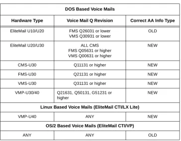
Table 2-1
Voice Mail AA-Info Settings ... 2-258
Table 2-2
Card Interface Slot Assignment ... 2-631
Table 3-1
Automatic Route Selection to Route Number Assignment ... 3-21
Table 3-2
Route Number to Trunk Group/RAB Selection and Digit Control ... 3-25
Table 3-3
Memory Block Data ... 3-44
Table A-1
Function Time Chart ... A-1
Table B-1
System Data Input ... B-4
Table B-2
Speed Dial Name Input ... B-5
___________________________________________________________________________________
S
ECTION
1
G
ENERAL
I
NFORMATION
A stored program controls the Electra Elite IPK system. When the system is initially
powered up, the CPUI( )-U( ) ETU scans all interface and AP slots to determine the
hardware configuration. The system stores this information and the default values in
the resident system program memory. After initially powering up the system, a trained
technician can change the resident system program to meet the specific needs of an
individual customer.
S
ECTION
2
P
ROGRAMMING
THE
S
YSTEM
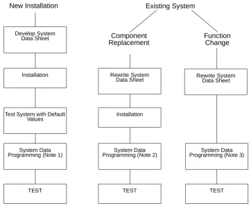
System data programming may be necessary when:
H
the system is installed for the first time.
H
components of an existing system are replaced.
H
functions of an existing system are changed.
2.1
Features of Programming
The following features are provided with Multiline Programming:
H
The system operates from default after initial power-up. Only the
parameters that change must be programmed.
H
System programming characters are displayed on the LCD of the
Multiline Terminal.
H
Several types of system programming can be entered at the same time.
H
Data programmed for one telephone (e.g., Tenant Mode, or Telephone
Mode) can be copied to another telephone.
Figure 1-1 Programming Flowchart
New Installation
Installation
Test System with Default Values
TEST System Data Programming (Note 1)
Develop System
Data Sheet
Component
Replacement
Installation
System Data Programming (Note 2)
Rewrite System Data Sheet
Function
Change
System Data Programming (Note 3)
TEST
Existing System
Rewrite System Data Sheet
TEST
Note 1:
For new installation, system default values are assigned when power is
turned on. Program the system data to be changed only.
Note 2:
For component replacement, program the relevant system data.
2.2
System Programming Modes
Modes and submodes are listed in
Table 1-1 Programming Modes
.
Table 1-1 Programming Modes
Line
Key
Mode Name
Line
Key
Submode Name
LK 1 System Mode
LK 1
CO Line
LK 2
ICM
LK 3
SLT
LK 4
Transfer/Automated Attendant
LK 5
SMDR/LCR
LK 6
DSS
LK 7
ESP
LK 8
PBR/Miscellaneous
LK 9
DISA
LK 10
Call by Call
LK 11
DTI
LK 12
ACD/UCD
LK 13
PRI
LK 14
ARS
LK 15
K-CCIS
LK 16
HUB
LK 2 Tenant Mode
N/A
N/A
LK 3 CO/PBX Line Mode
N/A
N/A
LK 4 Telephone Mode
N/A
N/A
LK 5 Trunk Group Mode
N/A
N/A
LK 6 Copy Mode
LK 2
Tenant Mode Copy Assignment
LK 3
CO Line Mode Copy Assignment
LK 4
Telephone Mode Copy Assignment
LK 5
Trunk Group Mode Copy Assignment
LK 7 ETU Mode
LK 1
Card Interface Slot Assignment
LK 2
Telephone Type Assignment
LK 3
MIF Assignment
2.3
Before Programming
The technician should check the ROM version and the port numbers before
programming the system.
2.3.1
Check Points
H
Confirm the ROM Version
The available features depend on the ROM version. Refer to
Memory Block 8-1 (ROM Version Confirmation), or from any
idle Display Terminal, press
A
and
C
.
H
Confirm the Port Number
Port numbers are used for system programming. Refer to
Memory Block 7-1 (Card Interface Slot Assignment).
To confirm station numbers press
A
and
D
. The display
indicates the station number and the port number.
2.3.2
Preliminary Points
H
Select System Programming
Refer to
Section 2 Programming the System on page 1-1
.
LK 8 Special ModeLK 1
ROM Version Confirmation
LK 2
System Speed Dial Memory Clear
LK 3
Station Speed Dial Memory Clear
LK 8
Second Initialization
Table 1-1 Programming Modes (Continued)
Line
Key
Mode Name
Line
Key
Submode Name
# # # = T E L X X
T I M E D I S P L A Y
Station
After turning on power, the system data can be programmed using a Multiline
Terminal connected to port 01 or port 02 (the Multiline Terminal must be idle).
System programming can be performed while other Multiline Terminals in the
system are in use. Some data is written into memory immediately after the
programming process, but other data is not written until the stations or trunks
are idle. When the data is not written until a station or trunk is idle, the station
LCD displays DATA ENTRY, even after programming is complete, to indicate
that system data entry is still in progress. When the in-use stations become
idle, the data is written and the station LCD displays only the time.
The data programmed for applicable Memory Blocks is not written for the
following conditions:
H
When Multiline Terminals are in use:
J
Memory Block 2-01 (Trunk to Tenant Assignment)
J
Memory Block 2-05 (Line Key Selection)
J
Memory Block 2-07 (System Speed Dial Display Assignment)
J
Memory Block 4-09 (Telephone to Tenant Assignment)
H
When the PBR is in use:
J
Memory Block 1-8-01 (SLT or Automated Attendant/DISA to CPU
PBR Selection)
2.5
Programming Methods
2.5.1
Initializing the System
Turn on the new Key Service Unit (KSU) power supply. After
approximately 30 seconds, the system operates with the system
default values.
2.5.2
Using the Multiline Terminal for Programming
System programming can be performed using a Display Multiline
Terminal that is connected to station port 01 or 02.
Figure 1-2 Electra Elite IPK Multiline Terminal
shows the terminal in
the offline mode.
Figure 1-2 Electra Elite IPK Multiline Terminal
Message Waiting LED
Help Key Exit
Key
Flexible Line Keys
Recall Key
Redial Key Speaker
Key Answer
Key Transfer
Key
MIC Key
Hold Key Dial
Keys
Display (LCD)
Softkeys
Conference Key Feature
Key
Directory Key
Programming.
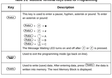
Table 1-2 Multiline Terminal Keys Used for Programming
Key
Description
K
~
I
Used to enter data from the dial pad or to specify a Memory Block location.J
Used to move the cursor to the left. The cursor moves one character space to the left each timeJ
is pressed.L
Used to move the cursor to the right. The cursor moves one character space to the right each timeL
is pressed.F
Used to select another mode. PressF
to switch modes as follows:Mode or submode selection: Returns to Program Mode.
Data No. Mode: Return to a mode or submode selection, or Program Mode (if no submode exists).
D
Each time the conference key is pressed, Memory Block item changes are as follows:Tenant Mode: The tenant number increments by one.
CO/PBX Line Mode: The CO/PBX line number increments by one.
Telephone Mode: The telephone port number increments by one.
Trunk Group Mode: The Trunk group number increments by one.
Y
Future use.A
Used to return to the previous page in system programming.X
Future use.H
Used to enter a pause in speed dial programming mode or to clear data in system programming mode.W
Flexible Line keys are used to specify a mode or submode when selecting a Memory Block or to select programming data for input.2.5.3
Entering Programming Mode
The following digital Multiline Terminals can be used to program the
system. Station ports 01 and 02 are automatically assigned as
programming stations.
H
DTP or DTH/DTR-8D-1 TEL
H
DTU-8D-2 TEL
H
DTP or DTH/DTR-16D-1 TEL
H
DTU-16D-2 TEL
H
DTP or DTH/DTR-32D-1 TEL
H
DTU-32D-2 TEL
Using the DTH-16LD -1 TEL to program is not
recommended.
To enter programming mode, the station must be idle (on-hook).
Perform the following procedure to go off-line.
1.
Press
A
.
2.
Press
H
.
B
This key is used to enter a pause, hyphen, asterisk or pound. To enter an asterisk or pound:
B
+J
= ,B
+L
= #B
+A
= AB
+B
= BB
+C
= CThe Message Waiting LED turns on and off after
J
orL
is pressed.E
Used to exit the programming mode (go back on-line).G
Used to write (save) data. After entering data, pressG
; the data is written into memory. The next Memory Block is displayed.Table 1-2 Multiline Terminal Keys Used for Programming
While off-line, the programming terminal cannot be signaled by
any system station. Off-line mode does not timeout.
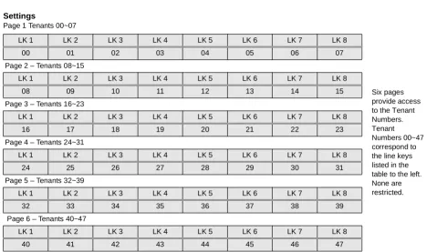
2.5.4
Page Switching
In Memory Block 1-1-18 (System Speed Dial Restriction by Tenant)
tenant numbers 00~07 are assigned to Flexible Line keys on the first
page. Tenant number 08~15 are assigned to the Flexible Line keys
on the second page. The tenant number corresponding to Flexible
Line key 1 of the current page is displayed on the right side of the
display.
During system programming, a value (data) is assigned to each
Flexible Line key. When the number of values exceeds the number
of Flexible Line keys, value assignments are displayed on additional
pages. The associated data can be entered on that page. The page
number is displayed on the right side of the LCD.
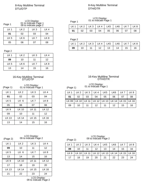
Figure 1-3 Page Display for 8-Key, and 16-Key Multiline Terminals
shows an example of CO/PBX line keys on each page and their
corresponding tenant numbers. In all cases, each page is
represented by eight line keys.
To navigate between pages, press
C
to access the next page,
or press
A
to return to the previous page.
P R O G R A M M O D E
Figure 1-3 Page Display for 8-Key, and 16-Key Multiline Terminals
(Page 1)
LK 1 LK 2 LK 3 LK 4
01 02 03 04 LK 5 LK 6 LK 7 LK 8
05 06 07 08
LK 9 LK 10 LK 11 LK 12
09 10 11 12
LK 13 LK 14 LK 15 LK 16
13 14 15 16
16-Key Multiline Terminal DTU/DTP
(Page 2)
LK 1 LK 2 LK 3 LK 4
09 10 11 12 LK 5 LK 6 LK 7 LK 8
13 14 15 16
LK 9 LK 10 LK 11 LK 12
17 18 19 20
LK 13 LK 14 LK 15 LK 16
21 22 23 24
16-Key Multiline Terminal DTH/DTR
(Page 1)
LK 1 LK 2 LK 3 LK 4 LK5 LK6 LK 7 LK 8
01 02 03 04 05 06 07 08 LK 09 LK 10 LK 11 LK 12 LK 13 LK 14 LK 15 LK 16
09 10 11 12 11 12 15 16
(Page 2)
LK 1 LK 2 LK 3 LK 4 LK5 LK6 LK 7 LK 8
09 10 11 12 13 14 15 16 LK 9 LK 10 LK 11 LK 12 LK 13 LK 14 LK 15 LK 16
17 18 19 20 21 22 23 24
LCD Display: 01 to indicate Page 1
LCD Display: 09 to indicate Page 2 LCD Display:
09 to indicate Page 2 8-Key Multiline Terminal DTU/DTP
Page 1
LK 1 LK 2 LK 3 LK 4
01 02 03 04 LK 5 LK 6 LK 7 LK 8
05 06 07 08
Page 2
LK 1 LK 2 LK 3 LK 4
09 10 11 12 LK 5 LK 6 LK 7 LK 8
13 14 15 16
LCD Display: 01 to indicate Page 1 09 to indicate page 2
8-Key Multiline Terminal DTH/DTR
LCD Display: 09 to indicate Page 2 Page 1
LK 1 LK 2 LK 3 LK 4 LK5 LK6 LK 7 LK 8
01 02 03 04 05 06 07 08 Page 2
LK 1 LK 2 LK 3 LK 4 LK5 LK6 LK 7 LK 8
09 10 11 12 13 14 15 16 LCD Display:
01 to indicate Page 1
Figure 1-4 Page Switching for Data Values
(Page 1)
LK 1 LK 2 LK 3 LK 4
Data 01 Data 02 Data 03 Data 04
LK 5 LK 6 LK 7 LK 8
Data 05 Data 06 Data 07 Data 08 16-Key Multiline Terminal
DTU/DTP
(Page 2)
LK 9 LK 10 LK 11 LK 12
Data 09 Data 10
LK 13 LK 14 LK 15 LK 16 LCD Display: 01 to indicate Page 1
LCD Display: 09 to indicate Page 2
LK 1 LK 2 LK 3 LK 4 LK5 LK6 LK 7 LK 8
Data
01
Data 02
Data 03
Data 04
Data 05
Data 06
Data 07
Data 08
LK 9 LK 10 LK 11 LK 12 LK 13 LK 14 LK 15 LK 16
Data
09
Data 10
2.5.5
Station Port Numbering Plan
Some Memory Blocks require entering a 2-digit port number. The
Electra Elite IPK system supports 48/120 ports, respectively.
Programming values for entry of Port Assignments are defined
below:
Port Assignments
Programming Value
01~99 01~99
100~109 A0~A9
110~119 B0~B9
120 C0