Estimation Of Vfto And Supression Methods In
420kv Gas Insulated Substation
R. Durga Rao, Abdul Zameer
Abstract: In Gas Insulated Substations because of low speed opening and closing operations of the isolator it results in evolving of Very Fast Transient voltages which are of extremely huge in magnitudes and will be comprising with peak frequencies, the generation of which may lead to dis proper functioning of instruments mainly secondary and they impose some disturbances which may cause malfunctioning and sometimes even lead to failures and may cause severe problems. These cause major problems in elements which are operating near to isolator or breaker and hence in this paper we have developed 420kv Electro Magnetic Transient Program designs to make proper analysis and we have mentioned outputs and mitigated with the help of techniques available.
Index Terms: Gas Insulated Substation, VFTO, EMTP Software.
————————————————————
I.
INTRODUCTION
The rise in requirement for electric power and also the rise in energy requirement in populated metropolis is main reason in running present high voltage system down to user. Bringing down the voltage from transmission to distribution level not yields economic advantages. Over the last 30years GIS have been used in power systems which are reliable with several units in service. GIS nearly of eight hundred kV are not only evolved, but in usage. Firstly, it is established wherever land prices are in peak value along with places where need of environment which has become major concerns up to a time, which resulted in speed advancement in its growth, it became not only economic but also common. GIS is compact, multi element assembly within a earthed encapsulation, that provides shielding of all energized components from the surroundings with insulating medium as SF6 gas.
II.
INTRODUCTION TO EMTP-RV
EMTP-RV plays a major role in studies related to energy systems in terms of designing a project in the field of engineering, it also helps in studying of miss-behaving of equipment’s and it offers enormous types of system designs. The performance index is been increased. EMTP is attractive power Transients Program and RV is Restructured Version. This device is utilized to survey transients in huge scale control in unusual electrical systems. The key highlights of EMTP-RV are like:
Power system safety issues
Modelling and study regarding huge systems and their full simulation.
Solutions for steady state which includes harmonics. New three-phase load flow Designing power system. Gives clear displaying of the system part and also
administration.
Automatic initialization from steady state solution. Switching of capacitor banks.
III. INTRODUCTION TO VFTO
A good execution for each portions transient behavior is done if precise description of every unit in system is obtained. (VFT) is belonged to high frequency range of power system network. The description of the elements of system should be done by taking the frequency limits of the transients that are to be simulated. The frequency for simulation will be in the range of 100 KHz to 100MHz. Disconnector or isolator are used mainly for dis-connecting operation for some portions of huge potential equipment’s with others like preventive operation. In Gas insulated systems we make utilization of electrical equal designs made out of lumped components, parameter lines, surge impedances and travelling time. Isolators primary usage is for switching of circuit breakers and dis-connection of bus section. They are also used for the transfer of load from bus bar to other bus bar. During the opening and closing operation of dis-connector it develops voltage at the switching contacts, which is because of opening and closing operation of the exiceted but unloaded networks, because of which capacitive currents in the range of few MA are generated. During this Disconnector operation a bridge is formed along the contacts of the breaker. This conducting bridge equals the voltage of the both sides of the Disconnector and thereby giving rise to high frequency distortions which leads to origin of VFTO’S.
IV. ESTIMATION OF DIFFERENT PARAMETERS
OF GIS
A. Calculation of inductance:
Utilizing beneath equation we can compute inductance, here length of area is l and radii is given by r1, r2, r3, r4.
L=0.001*l*[
————————————————
Mr. R. Durga Rao, Assistant Professor, Head of the Department in Electrical and Electronics Engineering Department, JNTUH College of Engineering Manthani, Email: [email protected]
Md. Abdul Zameer currently pursuing master’s degree program in Electrical Power Systems, JNTUH College of Engineering Jagtial, Email:
1784
Figure 1: Cross section of typical GIS System
B. Estimation of Capacitance in micro farad:
Using below mentioned equation we can obtain Capacitance, conductors here are to be in Cylindrical.:
Where ɛo = 8.854 * 10-12, ɛr = 1 b = Outer cylinder radius a = Inner cylinder radius l = Length of the section
C. Capacitance estimation with respect to Spacer
Here length can be assumed as thickness for Spacers. Material made of aluminum is used to make these and are of permittivity 4. To withheld enclosure which is outer one and conductor of inner one w make use of spacers.
D. Calculation of Variable Arc Resistance
In view of prior investigations in SF6 gas, Toepler's Spark Law is substantial for figuring of Variable Arc Resistance. The Variable Arc Resistance because of Toepler's formulae is given underneath
( )
∫ ( )
In the process of determining the time changing sparkle protection R(t), is computed till the point that it achieves an estimation of 2Ω and 6Ω. Here we obtain exact estimation of current by estimating accurate estimation of current along its integration across R(t). Hence we get with respect to time how much amount of potential passes across through this way. Here we have small qo because we have constant space across isolator and also qo plays key role for uneven fields.
V.
A TYPICAL 420 KV GAS INSULATED
SUBSTATION
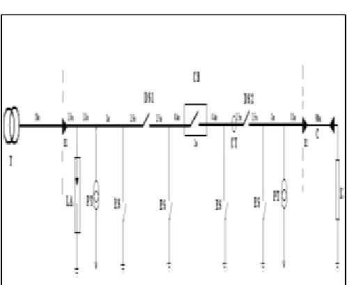
Figure: A Typical 420KV GIS Substation
VI.
Typical Section of EMTP Model of 420kV
GIS System
VII.
EMTP SIMULATION CIRCUIT OF DISCONNECTOR CLOSING OPERATION (RARC=0.5Ω)Figure: VFTO DURING CLOSING PHENOMENA
EMTP SIMULATION CIRCUIT OF DISCONNECTOR OPENING PHENOMENA (RARC=0.5Ω)
1786
Figure: COMPARISION OF VOLTAGES
VIII.
DIFFERENT TECHNIQUES TO MITIGATION FORVFTOs IN GIS SYSTEMS
At some point in isolators operating process and because of the ground failures within station in no time voltages with transient behavior happens will cause strain adjoining devices and instruments and secondary equipment in GIS. The impact of VFTO should be in consideration with the increment in voltage levels of GIS. For the safety of secondary systems it is necessary to supress these over voltages. The VFT present in system will be supressed with resistance which is in the limit of 400ohm-500ohm, placed across isloator. This technique consists resistor with value of five hundred ohm is hooked up acrossdis-connector switch and it is in series with a switch. When we see peak magnitude while the operation, in general while seconds restrike at load end the breaker is been closed.
EMTP SIMULATION CIRCUIT OF DISCONNECTOR CLOSING PHENOMENA WITH RESISTANCE SWITCHING
VFTO MITIGATION WITH FERRITE RINGS
Here we will be using rings that are made of material whos frequency in peak in magnitude named as ferrite, to mitigate high voltage transients in system, the above used rings of ferrite will be more powerful to suppress VFTs excessive frequency and these and these will absorb power that is present in waves since these are arranged to bus bars which are present near isolator terminal and has the capacity to successfully withstand to increasing travelling waves passing with respect to time. Details regarding nature along with layout aspects are being given for excessive voltage implementations Modelling of circuit to mitigate VFT is completed and equal design for mitigation process is shown in above figure , outputs at some stage of closing process have been given in figure below and this techniques has been tested and mentioned in particular, choosing these technique is of excessive important basically in case of for excessive voltage implementations and usage of this technique will mitigate VFT to a greater extent when compared to other techniques with respect to system and its should posses qualities of responce of fequency, saturation, magnetic conductivity and this properties play a key role in mitigating process of VFT and material chosen should posses good magnetic flux density, ring plays major role in determining mitigation of VFT and rings lossing energy is realized by
√
Equivalent characteristics
If we connect isolator and bus with inductance and impedance we can obtain the simulation system which represent this mitigation process for VFT and it is simple as like R and L parellel combination across isolator and it is the most effective technique to mitigate.
Ferrite rings Design features:
An alloy made up of manganese and zinc has been selected because it has good saturation with respect to its magneti, while its interior design that resembles toroid. While choosing required material of rings we should have in mind a few essential utility aspects. The material necessities are determined by the places wherein the frequncy of high attenuation. Crest levels of impendance can be provided if we have most appropriate ferriteto mitigate peak frequencies and with help of these we protect a large area. Here the ferrite type is dependent upon size. To mitigate we use manganese-zinc material which has peak ability and high degree of impence to mitigate properly. This alloy has good value regarding resistivity in the range of thosand and by using this technique voltage with peak frequencies can be mitigated well.
Figure: Model circuit of the ferrite ring.
Figure: EMTP SIMULATION CIRCUIT WITH FERRITE RINGS
Figure: VFTO with ferrite rings
VFTO AT DISCONNECTOR DURING SWITCHING OPERATION
S.No. Disconnector Operation Peak voltage magnitude
1 Closing operation 2.25
1788 VFTO’S SUPPRESSION WITH RESISTANCE
SWITCHING
S.No. Mode of operation
Arc resistance type(resistance
switching)
Peak voltage magnitude of vft (per
unit)
1 Closing
Fixed arc (without mitigation)
2.22
2 Closing Fixed arc (with
mitigation) 1.63
VFTO’S MITIGATION USING FERRITE RINGS
S.No. operation Mode of Mitigation type(ferrite rings)
Peak voltage magnitude of vft
(per unit) 1 Closing Without mitigation 2.2
2 Closing With mitigation 1.32
IX.
RESULTS
In GIS because of low speed operation of isolator used it results in evolving of VFT which are of extremely huge magnitudes and will be comprising with peak frequiencies the generstion of which may lead to dis proper functioning of instruments mainly secondary and they impose some disturbances which may cause malfunctioning and some times even lead to failures and may be cause severe problems. These cause major problems in elements which are operating near to isolator or breaker. In this case we have seen disturbances followed with extremely huge magnitides, so to eradicate this disturbaces and mainitain good working of GIS we are following some mitigation techniques. Very first technique we employ here is usage of some resistance across isolator which is named as resistance technique, but it has some problems and it cannot mitigate the extremely huge fequencies and voltages to a required operating level . Main contraints with this technique are with busducts which are needed to be stuffed full with gas and needed to bemaintained at required pressur, due to which resistor installing process has been beome very tough. Since VFT has peak amplitudes and frequiencies the above mitigation technique is seemed to be unfit to mitigate completely, and here a new technique which uses rings made of ferrite are being used to succesfully mitigate the above generated VFT. Peak magnitides are being succesfully mitigated by usage of above technique which involves usage of rings made with ferrite.
X.
CONCLUSION
GIS involves quick VFT because of isolator. Those VFT are charecterized with wave fronts which are very short periods around (approximately few ns) which lead to peak frequency in range of a few 100 KHz to MHz. Analysis and study regarding VFTOs within GIS has become imporatnt, to analyze of VFTOs, EMTP-RV programming has been utilized, computation are done. Parameters involving resistance of arc have been regarded in process involving VFTO analysis. Here we have discussed many VFTO mitigation strategies which are studied and the subsequent examination has done with help of EMTP-RV have been recorded with protection technique of switching with resistabce the mitigation of VFTOs are around 28% i.e before migitation it was 2.21p.u and it is 1.6p.u after mitigation. And with use of ferrite rings technique, the mitigation of VFTOs watched is around 41% i.e it becomes
1.3 after mitigation. So there might me some differences among results obtained from experimentation and simulation. But the usage of ferrite rings gives better protection and also we should improve our research regarding these diversity.
REFERENCES
[1]. J. Meppelink, K. Diederich, K. Feser and P. Pfaff. 1989. Fast Transients in GIS. IEEE Trans.Power Delivery. 10(1): 223-233.
[2]. Amir Mansour Miri and Zlatan Stojkovic. 2001.Transient Electromagnetic Phenomena in the Secondary Circuits of Voltage and Current Transformers in GIS (Measurements and Calculations). IEEE Trans. Power Delivery. 16(4): 571-575.
[3]. Nikhil Pathak. Mitigation techniques for supression of VFT in GIS. IEEE Conference on Power Electronics (ICPEICES-2016) 1-5 16.
[4]. D.Povh. Modelling and Analysis Guidelines of VFT. IEEE Power Engineering Review vol 16(10):71-71.
[5]. C.M. Wiggins, D.E. Thomas, F.S. Nickel, T.M. Salas and S.E. Wright. 1984. Transient Electromagnetic Interference in Substations. IEEE Trans. Power Delivery. 9(4): 1869-1884.
[6]. A. Said1, Ebrahim 2012. Mitigation of VFT at most Sensitive Points. Internation Journel of Electrical Engineering. Vol 4(3) 2012.
[7]. S.Rahmani, A.A.Razi-Kazemi .Investigation og VFTO in GIS. 2nd international conference KBEI.5-6 15
[8]. P. Osmokrovic, S. Krstic, M. Ljevak and D.Novakovic. 1992. Impact of GIS Parameters on the Toepler Constant. IEEE Trans. Electrical Insulation.27(2): 214-220.