1 Article
Control System Design for Vessel Towing System
Based on Backstepping Control Strategy
Dong-Hun Lee 1, Tran-Duc Quan 1* and Young-Bok Kim 2*
1 Department of Mechanical System Engineering, the Graduate School, Pukyong National University Nam-gu, Busan, Korea; [email protected]
2 Department of Mechanical System Engineering, Pukyong National University Nam-gu, Busan, Korea; [email protected]
* Corresponding authors : [email protected], [email protected]
Abstract:In this study, a motion control problem for the vessel towed by towing ship on the sea is considered. The towed vessel does not have self-control capabilities such that its course stability totally depends on the towing ship. Especially, in the narrow canal, river and busy harbor area, extreme tension is required during towing operation. Therefore, the authors propose a new control system design method in which the rudder is activated to provide its maneuverability. Based on the leader-follower system configuration, a nonlinear mathematical model is derived and a backstepping control is designed. By simulation results with comparison study, the usefulness and effectiveness of the proposed strategy are presented.
Keywords: towed vessel; towing ship; course stability, extreme tension; rudder; maneuverability; leader-follower; nonlinear model; backstepping control
1. Introduction
The development of control and measurement technology has made remarkable results regardless of its application areas and subjects. Especially, applications to the marine field are increasing and more recently extending to the area where autonomous navigation is possible. In this time, many control technologies had begun to be applied in ship motion control problems. The main issue was the problem of path control at a low or constant speed and. Therefore, complex and intricate research studies have been carried out.
In the previous research studies, a given goal was to maintain the right path in the wide ocean [1-6]. In other words, using the main propulsion device and the rudders, the sailing technologies have been developed.
Also, more sophisticated ship motion control strategies are necessary when the ship starts approaching to the harbor. To partially overcome the stability problem of the berthing process, several solutions were proposed. In these cases, the ship is moved in parallel to the seawall with only the side thrusters to complete the final step [7-12]. The objectives of these studies are to improve the stability of the docking operation at the final stage or restricted maneuvering environment.
The various ship motion control methods and techniques described above are implemented by installing the active control devices on the controlled vessel. In other words, it is natural that the motion control system is equipped on the controlled vessel itself.
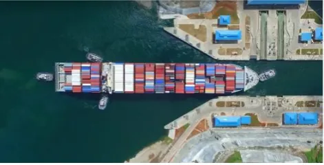
shown in Figure 1. Even though the propulsion system and active devices are equipped, they can be used due to sailing safety problem.
In the cases abovementioned, the tugboat leads and controls the towed vessels. However, it is difficult to make the towed vessels follow the tugboat’s moving route because of loss of maneuverability. Moreover, in harsh sea condition, safe maneuvering may be impossible.
About this issue, Fitriadhy et al. [13] gave an interesting result with mathematical model and course stability analysis. The obtained model presents the dynamics of tugboat and non-powered barge under wind attack. The result shows that the stability of towing system strongly depends on the wind attack angle and towing rope length.
However, the system stability and dynamic analysis were undertaken using the linearized model. Especially, it is evident that some useful strategy such as something active devices is necessary to occupy system stability and maneuverability.
If we insist on the conventional and inactive methods, more stable and better sailing performance could not be preserved. In the result, the severe accidents may occur due to the wave disturbance and complicated maneuvering environment induced by other vessels passing by. Needless to mention, if the towed vessel deviates from the path of the tugboat, collision possibility with other ships may increase.
Considering this fact, in this study, a new method to obtain a solution to above problem is discussed. To facilitate the maneuverability for non-powered vessel, the authors introduce a novel strategy based on the leader-follower concept. It is a control system method for the towed and towing vessel system shown in Figure 2. For giving the minimal function to the powerless towed vessel, it is considered that the vessel has the rudder which is controllable.
Practically, the rudder or portable propulsion system can be additionally provided for the non-powered vessels (such as barge ships) and controlled. Furthermore, the ships sailing in the narrow and restricted waters condition can be controlled by remote control system, tugboats and cooperation of various systems (see Figure 1). In this case, if we use the rudders of the non-powered vessel, needless to say, something excellent and sufficiently improved maneuverability can be obtained.
Therefore, the authors consider that an appropriate number of rudders are installed on the towed vessel. That is, the authors try to improve the steering stability and performance of the non-powered towed vessel without controlling of propulsion force. In this study, the dynamics of controlled vessels is described by nonlinear model, and the nonlinear controller is designed.
The simulation results are given to evaluate the control performance with comparison studies.
2. System Modelling and Controller Design
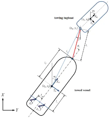
In order to design the control system, having a mathematical model that describes the dynamics of the system is compulsory. As shown in Figure 3, the towed vessel does not have any self-thrust force based on the assumption given before. Also, it is assumed that two rudders are adequately installed at arbitrary positions to keep robust system stability and improve maneuverability of the towed vessel. However, there is no constraint on the rudder numbers but it needs one more. The reason of providing two rudder system is that the vessel for future study in experiment is equipped with two rudders. In the real towing operation, it is possible to activate and use them for improving sailing stability.
In Figure 3,
l
ris length of rope connecting the towing tugboat and towed vessel. It is assumed that the length change ofl
r is sufficiently small and the mass of the rope is relatively small.Figure 3. Vessel towing system description.
2.1. Motion of Towing Tugboat
In this study, surge, sway and yaw motions of towing tugboat in the horizontal plane are taken into consideration. Then the 3-DOF equation of motions is derived adequately as follows [3]:
( )
1 1 1
1 1 1 1 1 rope
R v
M v D v
=
+ = −
where
3 1 1, 1, 1T
x y R
= represents position
(
x y1, 1)
and heading angle
1 in the earth-fixed frame;
31 1, 1,1
T u v r R
= describes the surge, sway and yaw rate of ship motion in the body-fixed frame;
1 [ 1 1 1] T
x y
=
is thrust vector and denotes surge force, sway force and yaw moment around the center of gravity of the towing tugboat; the vector [ 1 1 1]T rope xr yr r
=
denotes surge force, sway force and yaw moment made by the towing tugboat. The rotation matrix in heading directionR( )
1describes the kinematic equation of motion by Equation (3).
( )
1 11 11cos sin 0
sin cos 0
0 0 1
R
− = (3)Moreover,M1 R3 3
is the inertia matrix including the added mass as described as Equation (4). For control application, the vessels motion is restricted to low frequency. The wave frequency is assumed to be independent of added inertia which impliesM1=0.[3]
1 1
1 1 1 1
1 1 0 0 0 0 u v r
v z r
m X
M m Y Y
N I N
− = − − − − (4)
Finally,
( )
13 3 1
D v R is the damping matrix and, it is a function of the relative velocity between the vessel and the current. In low-speed applications, the damping matrix is assumed to be constant [3], and defined as follows
1
1 1 1
1 1 0 0 0 0 u v r v r X
D Y Y
N N − = − − − − (5)
The parameters shown in Equation (4-5) are summarized as follows: 1
m
: body mass of towing tugboat1 z
I : moment of inertia about z axes
1, 1, 1
u v r
X Y Y : additional mass 1
,
1v r
N
N
:
additional moment of inertia1, 1
u v : x y1, 1direction velocity component
2.2. Motion of Towed Vessel
Same as the description of towing tugboat, the 3-DOF equation of the towed vessel motion is derived as follows:
( )
2 2 2
2 2 2 2 2
R v
M v D v
= + = (6) (7) where 2 [ 2 2 2]
T
x y
=
denotes surge force, sway force and yaw moment. The actual actuation
2 of the towed vessel is generated by the traction force of the rope and the rudders. And R( )
2 ,M D2, 2are defined in the same manner ofR
( )
1 ,M D1, 1 respectively.As shown in Figure 3, we consider that the connecting point
(
x y
0,
0)
at the tugboat is the tracking target of the towed vessel, since the leading tugboat tows the controlled vessel with rope. It means that the tracking route is automatically generated by the rope connecting point of towing vessel. Then, the towed vessel motion can be solved by using the weather optimal positioning control (WOPC) method [3,14] which is a useful method for deriving a solution of this issue.The parameters shown in Figure 3 are denoted as follows:
(
x y
1,
1)
: gravity center of the towing vessel(
x y
2,
2)
: gravity center of the towed vessel2
: heading angle of towed vessel
: relative angle made by the target position and the control position( 1, 2)
i i
= : rudder rotation angle
r
l
: rope length for connecting two vesselsT
l
: distance from the gravity center to the rope connecting point of the towed vessels
l
: distance from the center of rudder #1, #2 to the gravity center of the towed vesselss
l
: distance from the center of rudder #1, #2 to the gravity center of the towed vessel in surge direction.The Cartesian coordinates
( ,
x y
2 2)
is related by using polar coordinates as follows: 2 0 ccos
x
=
x
+
l
2 0 c
sin
y
=
y
+
l
(8) (9) where,
(
) (
2)
22 0 2 0
2 0 2 0
atan 2(
,
)
c
l
x
x
y
y
y
y x
x
=
−
+
−
=
−
−
(10) (11) The derivative of Equations (8) and (9) are as follows:
2 0 2 0
cos
sin
sin
cos
c c c cx
x
l
l
y
y
l
l
=
+
−
=
+
+
(12) (13)From Equations (12) and (13), 2
2,
2,
2
3T
x y
R
=
can be expressed as0 2
0 2
cos
sin
0
1
0
0
1
0
sin
cos
0
0
0
0
1
0
0
1
0
0
1
0
0
c c
l
x
l
y
−
=
+
(14)Define the state vectors as:
0 0 0 2
,
cl
x
p
y
x
=
=
(15)Then a new kinematic relationship can be written as in terms of the vectors
p
0andx
:( ) ( )
2 R H lc x Lp0
=
+ (16)where,
( )
cos
sin
cos
sin
0
0
0
0
1
R
−
=
,( )
1
0
0
0
0
0
0
1
c c
H l
l
=
,1
0
0
1
0
0
L
=
(17)From Equation (16), Equation (6) can be written as following differential equation
( )
2 2 0
( ) ( ) T
T v T R Lp
x= x − x
(18)1
2
( )
( )
c T( ) (
)
T
x
=
H
−l R
R
(19)To facilitate the convenience of expression, define
T
(x)
=
T
,
H l
( )
c=
H
,
M v
2( )
=
M
2,
2
( )
2D v
=
D
. Therefore, the Equation (18) can be represented as follows: 12
x
(
2)
0T
T
R
Lp
=
−+
(20) And, time differentiation of Equation (20) is
1 1
2
x
x
(
2)
0(
2)
0T T
T
T
R
Lp
R
Lp
=
−+
−+
+
(21) In the results, from the Equation (18), Equation (20) and (21), the towed vessel model Equation (7) is represented as
0 0 2
[ ( , ,
,
)
]
x
x
Tx
x x
M
+
D
=
T
−q
p p
+
(22)where
2 0 0 2 2 0 2 2 0 2 2 0
1 1 1
2 2 2
( , x,
,
)
(
)
(
)
(
)
,
T T T
T T T
x x
q
p p
M R
Lp
M R
Lp
D R
Lp
M
T
M T
D
T
D T
T
M T
− − − − − −
= −
−
−
=
=
+
(23) (24)
3. Control System Design
The goal of the control system design is to achieve desirable tracking performance with course stability. Basically, the positions and heading angles of both towing and towed vessel should follow the desired trajectory in the designed manner. It is natural that the towing tugboat is accordingly controlled such that a desired trajectory for the follower is made. Also, the towed vessel should be controlled to go after the towing tugboat accurately.
Based on these objectives, the authors design two control systems individually.
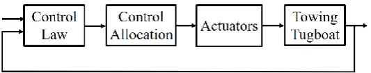
3.1. Control System Design for the Towing Tugboat
The control structure of towing tugboat is shown in Figure 4. The nonlinear PID controller is derived as
1 1 1 1 1 1 1 1 1 0
( ) ( ) ( )
t
PID KP d KD d KI d dt
=
− +
− +
− (25)where 1 is the actual motion vector, and d1is the desired motion vector of surge, sway position and yaw angle, respectively.
Figure 4. Control system configuration for towing tugboat.
3.2. Control System Design for the Towed Vessel
The main objective of the control design for towing system is controlling the towed vessel to go after the towing tugboat. To complete the given objective, we consider three concepts.
be
d= +
1 . Finally, the last requirement is controlling the heading angle of the towed vessel to be 2d 1
=
.Based on these definitions, the authors design a nonlinear control law based on backstepping technique. Then, we need to design the control law
2 such that the system in Equation (26) is stable.2
T T x x
M
x
+
D
x
=
T
−
+
T q
− (26)If we define the reference trajectory vector as
[
2]
3T d
=
l
cd
d d
R
x
, the control designprocess based on nonlinear control framework is summarized as follows. Step 1: Define the error variables
1 d
z
= −
x
x
2
z
= −
x
(27) (28) wherez1is the tracking error dynamics and
is the stabilizing vector :1
d
z
=
x
−
(29)and ( 0) is a positive definite diagonal matrix.
From Equations (28) and (29), the derivative ofz1is represented as follows:
1 d 2 1
z
= −
x
x
=
z
−
z
(30)Consider a Lyapunov function candidate and its derivative given as Equation (31) and Equation (32), respectively.
1 1 2 1
1 1 2 1 1 2 1 1 2 2
1 2
T P
T T T
P P P
V
z K
z
V
z K
z
z K
z
z K
z
=
=
= −
+
(31) (32) where
K
P2( 0)
is a diagonal matrix.Step 2: From Equation (28), the following expressions are obtained. 2
z
= +
x
2z
x
= +
(33) (34) This implies that the towed vessel motion described in Equation (26) can be expressed in terms ofz2 and
as following.2 2 2
T T
x x x x
M z
+
D z
=
T
−
+
T
−q
−
M
−
D
(35)Consider an additional Lyapunov function candidate
2 1 2 2
1 2
T x
V
= +
V
z M z
(36)then its time derivative yields
2 1 2 2 2 2
1 2
T T
x x
V
= +
V
z M z
+
z M z
(37)Also, the time derivative ofV2can be expressed by substitution Equation (32) and (35) to Equation (37) as
2 1 2 1 1 2 2 2 2 2 2 2
1 2
[
]
T T T T T T
P P x x x x
V
= −
z K
+
z
z K z
+
z T
−
+
T
−q
−
M
−
D
−
D z
+
z M z
(38) To satisfy condition V2 0, the control law should be chosen as2 2 1 2 2 2 2
1 2
T T T
x x P D x
T
−
= −
T q
−+
M
+
D
x
−
K z
−
K z
−
z M z
(39)2 1 2 1 2 2 2
0
T T
P D
V
= −
z K
−
z
z K z
(40)We need to calculate control gains
,
K
P2,
K
D2 such that the conditionV
2
0
holds. Then, Equation (39) implies thatz
1 andz
2 are bounded. Finally, the designed control vector is obtained as2 2 1 2 2 2 2
1 2
T T
x x P D x
q T M D K z K z z M z
= − +
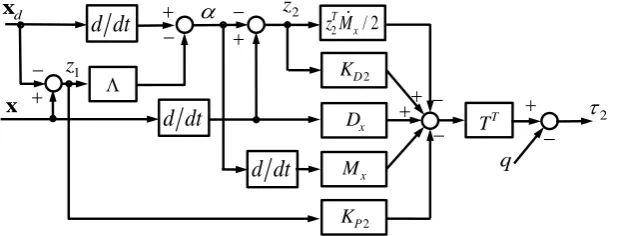
+ x− − − (41)Additionally, the configuration of the proposed backstepping control system for the towed vessel can be illustrated as Figure 5.
Figure 5. Configuration of the designed backstepping controller for the towed vessel.
Second derivative of V2 is bounded and V2 is uniformly continuous, since the
z
1 andz
2 isbounded. According to the Barbalat’s lemma, it can be obtained that
V
2→
0
as t→ . Then, it is clear that the system Equation (34) is globally asymptotically stable with the control law of Equation (41). Therefore the tracking error and its derivative converges to zero.4. Simulation
Here we investigate the tracking performance of the towed vessel. As abovementioned, the tracking route of the towed vessel is produced by the towing tugboat. The towing tugboat follows the defined target trajectory such that the tracking route for towed vessel is generated.
The towed vessel is a model ship which was employed in previous study [9]. For the convenience, the physical parameters of towed vessel model are used for towing tugboat’s also. It means that two vessels are same one.
Subsequently, the parameters of ships represented in Equations (1), (2), (6) and (7) are given as follows:
1 2
2
22.5[kg]
0
0
0
41.5[kg]
0.65[kg m]
0
0.65[kg m] 5.26[kg m ]
M
M
=
=
(42) 1 2 21.74[kg/s]
0
0
0
6.7[kg/s]
0.5[kg m/s]
0
0.5[kg m/s] 1.78[kg m /s]
D
D
=
=
(43)We define the rope length and rudder positions illustrated in Figure 3 as:
1.0[m],
1.0[m],
0.8[m],
0.7[m],
0.1[m]
r T b s ss
l
=
l
=
l
=
l
=
l
=
Then, the PID control gains for the towing tugboat are chosen as
d dt
− + dx
q
z
22 D K x D x M 2 / 2
T x z M 2 P K T T
x
+ − + −d dt
d dt
− + + +−
−
2
11
diag{1.4230, 3.4992, 3.4117}
P
K
=
1
diag{0.2928, 0.7200, 0.7020}
D
K
=
1
diag{0.0018, 0.0044, 0.0043}
I
K
=
(44) (45) (46) And, the backstepping control gains for the towed vessel are calculated as
Definitely, the obtained control gains preserve the system stability. The effectiveness of the proposed control strategy will be verified by performance comparison with PID control.
The tugboat and the towed vessel should track the reference trajectory with small error as possible as they can.
In this study, the authors consider a circle type reference signal. The turning reference is a circle with radius 25[m] and induced by following equations:
25sin(
90)
d
x
=
t
25
25cos(
90) (if
180)
d
y
= − +
t
t
,y
d=
25 25cos(
+
t
90) (if
t
180)
(50) (51) Where, the starting position of the tugboat is set asx01=0.0[m], y01=0.0[m],
01 =0.0[rad]. And the distance between the tugboat and the towed vessel at the initial state is defined as0 2.0[m],
c
l =
0 =0.0[rad],
02=0.0[rad].Based on these preparations, the simulations were operated, and the results are illustrated as following.
In Figure 6, (a) shows the motions of the towing and towed vessels with PID control for the turning route trajectory. The dashed thin line is the reference trajectory, the thick dashed-dot line is the moving route and the heading angle of the towing vessel, whereas the solid line indicates the motion of the towed vessel. And, (b)~(d) show the surge, sway motions and yaw angles of two vessels, respectively.
Then a backstepping control is applied to the towed vessel in the same manner of PID control illustrated in Figure 6. However, the towing tugboat is controlled by PID control scheme.
The simulation was performed in the same process as the PID control. The results are derived as following.
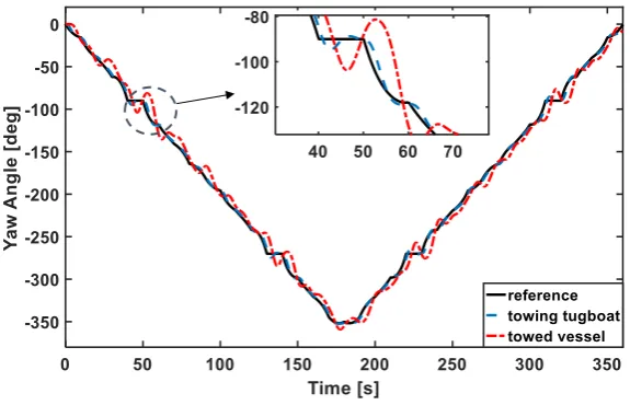
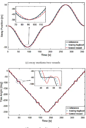
Figure 7 (a) shows the tracking performance for the turning route. And, (b)~(d) illustrate the surge and sway motions and yaw angles of two vessels, respectively.
Evidently, we can find out definite difference between the two simulation results. Especially, the rout tracking performance of the towed vessel is definitely improved.
Also, Figure 8 shows the relative motions of towing tugboat and towed vessel. The relative distances are shown in Figure 8 (a), while Figure 8 (b) shows the relative heading angles. Especially, the reference distance shown in Figure 8 (a) is given as 2[m], because the length lr+ =lT 2[m].
In each figure, the dashed line shows the reference made by the towing tugboat, whereas the solid line indicates controlled response of the towed vessel, respectively.
In additional, the error dynamics z1and z2 defined in Equations (27) and (28) are shown in Figure 9. Where the errors are minor and neighborhood around zero.
From the simulation study, the towed vessel can always follow the towing tugboat stably and adequately.
In the end, it was confirmed through this study that more stable and superior sailing performance can be secured if the rudder function is alive with minimal control function on the towed vessels.
2
diag{4.14,
4.6,
3.6}
P
K
=
2
diag{0.07, 0.18, 0.4}
D
K
=
diag{0.049, 0.50, 0.93}
=
(a) turning route tracking performances of two vessels
(b) surge motions of two vessels
(d)yaw angles of two vessels
Figure 6. Control performance of PID control.
(a) turning route tracking performances of two vessels
(c) sway motions two vessels
(d) yaw angles of two vessels
Figure 7. Control performance of backstepping control.
(b) angles
Figure 8. Relative response of towing tugboat and towed vessel.
(a) errors in distance and degree
(
z
11= −
l
cl
cd,
z
12= −
d,
z
13=
2−
2d)
(b) errors in velocity and angular velocity
(
z
21= −
l
cl
cd, z
22= −
d, z
23=
2−
2d)
5. Conclusion
In this study, the authors have considered the control problem of the towing system consisting of two vessels, and proposed a new method to solve this critical issue. The vessels are connected each other with rope and work as the leader and follower during towing operation, respectively. The towing vessel has the power propulsion system. On the other hand, the towed vessel is connected to the leader and does not contain any active system except the rudder. Therefore, the safe sailing and robust maneuvering are not preserved. If it is strongly exposed to hard environment condition, a serious collision accident may not be unavoidable. To overcome this limitation, the authors proposed a new control strategy by providing the rudder action in the towed vessel. In this system configuration, the rudders are newly installed on the towed vessel or used as it has, such that the towed vessel can occupy the safe sailing and course keeping ability at last.
The full mathematical model of two connected vessels has been newly obtained, and a nonlinear backstepping controller are applied for simulation study. The simulation results with comparison study demonstrate that the proposed control strategy preserve the accurate tracking performance and safe sailing of towed vessel.
References
1.
Yamato, H.; Uetsuki, H.; Koyama, T. Automatic berthing by the neural controller. Proc. 9th Ship Control Systems Symposium USA 1990, 3, 183-201.2. Zhang, Y.; Hearn, G.E.; Sen, P. A multivariable neural controller for automatic ship berthing. Journal of IEEE
Control System1999, 17, 31-44.
3. Fossen, T.I.; Marine Control System-Guidance, Navigation, Rigs and Underwater Vehicle, Trondheim,
Norway: Norwegian University of Science and Technology 2002.
4. Lopez, M.J.; Rubio, F.R.; LQG/LTR control of ship steering autopilots. Proceedings of the 1992 IEEE
International Symposium on Intelligent Control 1992, 447-450.
5. Michiel, W.; Erjen, L.; Kristin, Y.P.; Henk, N. Output feedback tracking of ships. IEEE Transactions on Control
Systems Technology2011, 19, 2, 442-448.
6. Zwierzewicz, Z. On the ship trajectory tracking LQG controller design. Transactions on the Built Environment
1999, 42, 399-406.
7. Bui, V.P.; Jeong, J.S.; Kim, Y.B.; Kim, D.W. Optimal control design for automatic ship berthing by using bow
and stern thrusters. Journal of Ocean Engineering and Technology2010, 24, 2, 10-17.
8. Bui, V.P.; Kawai, H.; Kim, Y.B.; Lee, K.S. A ship berthing system design with four tug boats. Journal of
Mechanical Science and Technology2011, 25, 5, 1257-1264.
9. Bui, V.P.; Kim, Y.B. Development of constrained control allocation for ship berthing by using autonomous
tugboats. International Journal of Control Automation and Systems2011, 9, 6, 1203-1208.
10. Tran, A.M.D.; Ji, S.W.; Kim, Y.B. A ship berthing system design by cooperating with tugboats and dampers.
Journal of Drive and Control2014, 11, 3, 7-13.
11. Tran, A.M.D.; Kim, Y.B. Dynamic identification and robust control performance evaluation of towing rope
under rope length variation. Journal of the Korean Power System Engineering2016, 20, 2, 58-65.
12. Lee, D.J.; Kim, J.K.; Kim, B.S. Design of an automatic winch system for small fishing vessel. Journal of the
Korean Society for Fisheries and Technology2000, 36, 3, 157-165.
13. Fitriadhy A.; Yasukawa, H.; Koh, K.K. Course stability of a ship towing system in wind. Ocean Engineering
2013, 64, 135-145.
14. Tran, D.Q.; Lee, D.H.; Kim T.W., Kim Y.B. Park, H.C. A study on maneuvering performance improvement