ISSN 2348 – 7968
Design & Implementation of Disc Brake Rotor By using
Modified Shapes
R. S. Kajabe1, R.R.Navthar2, S.P.Neharkar3
1Mechanical Engg,PVVP COE, A.Nagar 2Mechanical Engg,PVVP COE, A.Nagar
3Mechanical Engg, JCOE, Pune
ABSTRACT:
This work is presented with “Design of disc brake with modified shapes” which studies about on disc brake rotor by modeling & analysis of different shapes of slots of different vehicle’s disc brake rotor with same outer diameter & inner mounting position of holes on wheel hub as like Bajaj Pulsar 150.Analysis done on real model of disc brake rotor of Bajaj pulsar 150 and disc brake rotor of different shapes of slots of different vehicle’s disc brake rotor. Therefore, it gives optimize stress, deformation & weight of the modified disc brake rotor & also good heat dissipation. On the basis of weight parameter implementation of new disc brake rotor is done. Hopefully this project will help everyone to understand experimental verification of disc brake rotor and how implemented disc brake works more efficiently, which can help to reduce the accident that may happen in each day
Keywords- Disc brake, optimize, slots, heat
dissipation, experimental verification.
1. Introduction
In this project we study about disc brake rotor analysis of different shapes of slot. Static structural and steady state thermal analysis is done on
real model of disc brake rotor of Bajaj Pulsar 150ccDTSi and also on different shapes of disc brake rotor with keeping same outer diameter and inner mounting position of hole on wheel hub. Different shapes of slots are to modify the von mises stresses, deformation & weight of disc rotor as well as good heat dissipations across the disc brake rotor. Therefore, we can optimize number of shapes to estimate the optimum von mises stresses, deformation & weight the in disc brake rotor.
ISSN 2348 – 7968
2.MATHEMATICAL MODELING
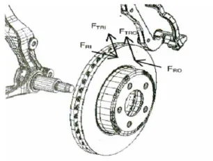
2.1 Tangential force
Fig. 2.1 Forces acting on rotor due to contact with brake pads.
The forces acting on the inner and outer rotor faces due to contact with brake pads are shown in Fig. 5.1
Hence the expressions for tangential force were:
2.1.1 Tangential force between pad and rotor (inner face)
∗ 1
2.1.2 Tangential force between pad and rotor (outer face)
∗ 2
2.2 Brake Torque
2.2.1 Brake torque in case of pad and rotor difference materials
The expression for brake torque was developed as a function of the two tangential forces and the effective radius of the pad/rotor interface.
T μ ∗ F μ ∗ F . Reff 3
2.2.2 Brake torque in case of pad and rotor same material
With the assumption of equal coefficients of friction and normal forces FR on the inner and outer faces:
2 ∗ ∗ ∗ 4
2.3 Distance travelled (in meter) by the vehicle
before it come to rest
Let x = Distance travelled (in meter) by the vehicle before it comes to rest.
Tangential braking force acting at the point of contact of the brake and work done = FT. x;
When,
F F F 5
Kinetic energy of the vehicle mv
2 6
In order to bring the vehicle to rest, the work done against friction must be equal to kinetic energy of the vehicle. Therefore equating Equation 10 and Equation 6,
.
2 7
Let N = Required number of revolution.
Distance travelled by the vehicle (x),
(8)
Where D = Diameter of rotor disc brake standard
ISSN 2348 – 7968
2.4 Calculation
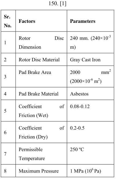
In This Project Study Standard of Vehicle name “Bajaj Pulsur 150”
Table No. 2.1Standard specification of Bajaj Pulsar 150. [1]
Sr.
No. Factors Parameters
1 Rotor Disc
Dimension
240 mm. (240×10-3
m)
2 Rotor Disc Material Gray Cast Iron
3 Pad Brake Area 2000 mm
2
(2000×10-6 m2)
4 Pad Brake Material Asbestos
5 Coefficient of
Friction (Wet)
0.08-0.12
6 Coefficient of
Friction (Dry)
0.2-0.5
7 Permissible Temperature
250 ºC
8 Maximum Pressure 1 MPa (106 Pa)
2.5 Tangential force
2.5.1 Tangential Force between Pad and Rotor. (Inner Face), FTRI
F μ ∗ F
Where FTRI = Normal force between pad brake and rotor (inner)
μ1 = 0.5
F Pmax
2 PadBrakeArea
So,
F μ ∗ F
F 0.5 ∗ 1 10
2 ∗ 2000 10
F 500 N
2.5.2 Tangential Force between Pad and Rotor (Outer Face), FTRO
In this FTROequal FTRIbecause same normal force and
same material.
2.6 Brake torque (TB)
With the assumption of equal coefficients of friction and normal forces FR on the inner and outer faces:
T F ∗ R 9
FT = 1000 N.
R = Radius of rotor disc.
So, T = 1000 ∗ 120 ∗ 10
T = 120 N.m
2.7 Brake distance (x)
We know that tangential braking force acting at the point of contact of the brake, and
Workdone F .∗ x 10
Where F F F
x = Distance Travelled (In meter) By The Vehicle Before It Come To Rest.
ISSN 2348 – 7968
Kineticenergy mv
2 11
Where = Mass of vehicle
= Velocity of vehicle
In order to bring the vehicle to rest, the work done against friction must be equal to kinetic energy of the vehicle. Therefore equating (Eq. 10) and (Eq. 11)
F . x mv
2
Assumption = 100 km/h = 27.77 m/s
M = 132 kg. (Dry weight)
So we get /F
x = ∗ . /1000
x = 50.89 m
2.8 Non Standard Rotor disc calculation
In this case calculate same rotor disc standard but difference rotor dimension.
Table No.2.2 Brake torque & Tangential force calculation of different diameters.
Sr.
No.
Rotor Disc
Dimension
FTRI FTRO FT TB X
1 300 mm 500
N 500 N 1000 N 150 N.m 50.89 m
2 275 mm 500
N 500 N 1000 N 137.5 N.m 50.89 m
3 240mm 500
N 500 N 1000 N 120 N.m 50.89 m
4 200 mm 500
N 500 N 1000 N 100 N.m 50.89 m
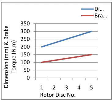
Forces and torque analysis on the rotor disc was studied which, are divided by tangential force, brake torque, and the motorcycle's stopping distance. The result of force value on rotor disc by tangential force and the motorcycle's stop distance are similar. When dimension of disc brake was changed, the value of brake torque was different by rotor disc dimension at 300 mm, which has the most value of brake torque, and rotor dimension at 200 mm, which has the least value of brake torque.
Table No.2.3 Relationships between Dimension of rotor disc and Brake torque.
Rotor Disc
No. 1 2 3 4 5
Dimension (mm) 2 0 0 24 0 25 0 27 5 30 0 Brake Torque (N.m) 1 0 0 12 0 12 5 13 7.5 15 0
Graph 2.1 Relationships between Dimension of rotor disc and Brake torque.
0 50 100 150 200 250 300 350
1 2 3 4 5
Dimension (mm) & Brake Torque (N.m)
Rotor Disc No.
ISSN 2348 – 7968
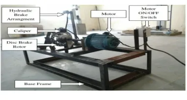
3. Experimental Setup& Result:
Disc is rotating at constant rpm due the motor arrangement. Brake is applied periodically to reduce or to stop the disc. While applying the break the friction is takes place between the disc and friction pad. These friction forces resist to the motion of disc, due to the friction between the disc and friction pad heat is generated in the disc and it distribute over the disc
Fig 3.1Experimental Setup
The temperature at various locations is measured periodically by the non-contact type sensor such as infra-red sensor. The speed of the vehicle travel and consequently of the air circulation. Since the process of heat transfer by radiation is not too important but heat generated in the disc is dissipated by the conduction as well as convection mode of heat transfer.
Experimental Result:
Table No. 3.1 Result of original disc brake rotor
.
Table No. 3.1 shows the variation in temperature distribution by region-wise diameter according to software & experimental results in original disc brake rotor.
Table No.3.2Result of modified shape 4 disc brake rotor
Table No. 3.2 shows the variation in temperature distribution by region-wise diameter according to software & experimental results in modified shape 4 disc brake
Graph 3.1Experimental result of original & modified shape 4 disc brake rotor
0 20 40 60 80 100 120 140 240-220 220-200 200-180 180-170 170-110
I II III IV V
Average Tem
p.
in º
C
Region-wise diameter (mm)
Experimental Result of original disc brake rotor (Average Temp. in ºC) Experimental Result of modified disc brake rotor (Average Temp. in ºC) Sr. No. Region-wise diameter (mm) Software Result (Average Temp. in ºC) Experimental Result (Average Temp. in ºC) Region Diameter
1 I 240-220 238.33 115
2 II 220-200 191.67 88.3
3 III 200-180 145 66.7
4 IV 180-170 98.33 43.2
5 V 170-110 51.67 25
Sr. No. Region-wise diameter (mm) Software Result (Average Temp. in ºC) Experimental Result (Average Temp. in ºC) Region Diameter
1 I 240-220 226.66 107.2
2 II 220-200 168.33 81.3
3 III 200-180 110 59.4
4 IV 180-170 75 39.2
ISSN 2348 – 7968
From graph 3.1 on the basis of experimental results it is clearly understand that average temperature occurs in modified shape 4 disc brake rotor is minimum as compared to original disc brake rotor.
Software Results
The highest stresses & deformations are reached at the contact surface disc pads. The rise in stresses & deformation is due to change in shape of disc brake rotor. For the four types of discs with original disc brake rotor, one notice that changes occurs in stresses, deformation & weight.
Table No.3.3 Results of Von mises, Deformation, Weight
S r. N o.
Disc Brake Rotor
Von-Mises Stresses
(MPa)
Deformatio n
(m)
We igh t
(K g)
Ma
x. Min. Max.
M in
1 Original disc brake rotor 083 19. 0.00971 3.695*10-3 0 1.052
2 Modified shape 1 disc brake rotor 19.67 0.00890 3.829*10-3 0 1.15
3 Modified shape 2 disc brake rotor 291 15. 0.022301 3.730*10-3 0 1.207
4 Modified shape 3 disc brake rotor 456 27. 0.009036 5.3427*10-3 0 1.026
5 Modified shape 4 disc brake rotor 707 20. 0.008189 5.6881*10-3 0 0.954
4. CONCLUSION
1. The static structural & steady state
analysis of disc brakes during periodic braking that performed are achieved
2. The weight of the modified shape 4 disc
brake is up to 0.954 kg which is reduced
about 100 grams than the original disc brake rotor.
3. Cost of the disc brake rotor ultimately
reduces due to minimization of the weight disc brake rotor.
4. Stress induced in modified shape 4 disc
brake rotor is 20.707 MPa which is
allowable. Maximum tensile strength of cast iron is 200MPa
5. During the continuous braking process
gives a different value of temperature Distribution as a result of the frictional heat generated on the rotor surface which is heat dissipated properly
REFERANCES
1. Sowjanya K., S.Suresh, “structural
analysis of disc brake rotor”, IJCTT, July 2013,vol. 4 Issue 7, pp 2295-2298 2. Daniel Das. A, Christo Reegan Raj V,
et. al. “structural and thermal analysis
of disc brake in automobiles”, IJLTET, May 2013, Vol. 2 Issue 3, pp 18-25. 3. Thilak V. M. M., “Transient analysis of
rotor disc of disc brake using ANSYS”, IJMIE, Aug. 2012, Vol. 2, Issue 8, pp. 502-514.
4. Guru Murthy N., Charyulu T. N., et. al.,
“Coupled structual / thermal analysis of disc brake”, IJRET, Dec 2012, Vol. 1, Issue 4, pp. 539-553.
ISSN 2348 – 7968
6. Thilak V.M.M., Krishnaraj R., et. al.
“Transient thermal and structural analysis of the rotor disc of disc brake”, IJSER, Aug. 2011, Vol. 2, Issue 8, pp. 1- 4.