Security Based Embedded Transition Inversion Code for
Information Interchange
Talari Srinivas/ M.Tech, & R Uma Susila/ Assist. Professor,
Dept of Electronics and Comm. Engineering, Goka raju Ranga raju Institute of Engineering and technology Hyderabad, India
ABSTRACT:
Serial link interconnection has been proposed for its advantages of reducing crosstalk and area. However, serializing parallel buses tends to increase bit transition and power dissipation. Several coding schemes, such as serial followed by encoding (SE) and transition inversion coding (TIC), have been proposed to reduce bit transition. TIC is capable of decreasing transitions by 15% compared to the SE scheme, but an extra indication bit is added in every data word to represent inversion occurrence. The extra bit increases the transmission overhead and the bit transitions. This paper proposes an embedded transition inversion (ETI) coding scheme that uses the phase difference between the clock and data in the transmitted serial data to tackle the problem of the extra indication bit with clock and data with shift row and mix column technique.
I.INTRODUCTION
Low power design, in a system perspective, happens at all levels of the digital electronic system stack. It is being done from the lowermost device level design to the topmost software design. And there are the intermediate levels where a lot of effort is being expended to make systems run at low power, keeping the compromise in performance to be minimum. The increasing density of the integrated circuits as postulated by Moore’s law makes it even more important to have low power systems since the power supply for such a dense integrated circuit may not keep track in size
with the miniaturization of the electronic components. Hence research is being made at all levels of a system stack. A system can consist of multiple components.
II.CONVENTIONAL ETI CODING
Although many coding algorithms can reduce the switching AF, most of them are designed for specific applications, such as video streaming or strongly correlated data. The TIC is one of the methods developed for random data.
Fig.1. ETI coding scheme for one serial link, word
length = WL, Nth = WL/2, and number of
transition = Nt.
An n/m ETI serial links with n input bit streams under degree of multiplexing m.
Each serial link has m input bit streams that are multiplexed by a serialize, followed by the ETI encoding. The encoded stream is transmitted through the serial link and followed by the ETI decoding and a deserializer. The ETI coding scheme includes the inversion coding and phase coding as shown in Fig. 1.
INVERSION CODING: Define the word
length (WL) as the number of bits in a data word and a threshold Nth as half of WL. A transition is defined as a bit changing from zero to one or from one to zero. For example, the bit stream “0100” has two transitions while “0101” has three transitions. When the number of transitions
Nt in a data word exceeds the threshold Nth, the bits in the data word should be encoded. Otherwise, the data word remains the same. When an encoding is needed in a data word, this method checks every two-bit in the data word, as Fig. 1 shows.
Since this operation is on a two-bit basis and only the second bit is inverted, it is called bit-two inversion (B2INV).
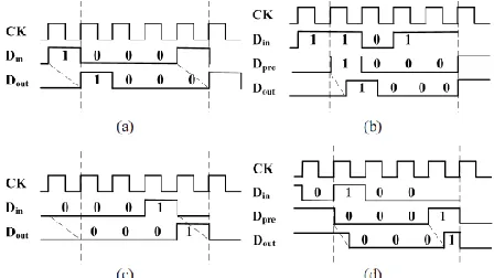
PHASE CODING: The ETI coding uses the
phase difference between the data and the clock to encode the indication information. Table I shows the corresponding output data word after TIC, ETI pre, and ETI. The ETI pre has the same data word as the TIC, except that it removes the extra bit bex. Removing the bex leaves eight sets of data words that are exactly the same. For example, there are two “1000” data words after the ETI pre coding. Within every data word duration, the phase difference between the data and the clock distinguishes these two data words, as Fig. 2 illustrates. Same
Dout “1000” in Fig. 2(a) and (b) is obtained
from Din “1000” and “1101” without and
with inversion. A half clock cycle difference between Dout and CK is shown in Fig. 2(b), indicating that Din has been encoded. The
Dout and CK are aligned in Fig. 2(a), indicating that Din has not changed. Dout “0001” is the same in Fig. 2(c) and (d) from
Din “0001” and “0100” without and with
inversion.
Fig:2. Dout “1000” obtained from (a) Din “1000” without encoding,(b) from Din “1101” with encoding. Dout “0001”
obtained from (c) Din“0001” without encoding, and (d) Din “0100” with encoding.
This approach is able to identify whether
Dout has been encoded or not as long as there is a half cycle delay between the Dout and CK. Although the phase difference can distinguish most of the data words of ETI pre, this method cannot be used for “0000” or “1111” because there is no transition inside the data word.
The overall architecture of the ETI scheme is shown in Fig. 3(a). We add the ETI pre block and the TIC architecture for clarity. The ETI pre does not provide the decision bit information so it cannot be decoded in the receiver. The ETI pre encoder is shown by the dashed box in the ETI encoder in Fig. 3(a). The TIC counts the transitions in the data word then uses this information to perform encoding. The transition indication bit is added to every data word to indicate whether there is an inversion or not. The decoder adopts the transition indication bit to perform the decoding, as shown in Fig. 3(b). In the ETI encoder part, the input data
(a)
(b)
Fig.3. (a) Overall architecture of the ETI scheme. (b) Overall architecture of the TIC scheme. ETI
pre encoder is marked by dashed line box. III. MODIFIED ETI SCHEME
The decision bit is also adopted in the phase encoder block to select the phase encoded or un-encoded data word. In the ETI decoder part, the phase decoder checks the phase difference between the clock and the data. The phase difference information is then used to generate the decision bit. The decision bit is used in the B2INV to decode the data words.
Fig.4. Modified ETI scheme
In this transformation the rows of the block state are shifted over different offsets. The amount of shifts is determined by the block
length. The proposed architecture implements the shift row operation using combinational logic considering the offset by which a row should be shifted.
The mix column in encryption and decryption done the columns to be mix and inverse of column mixing respectively. Inverse the operations like inverse byte sub transformation, inverse shift row, inverse mix column. The output waveform is shown in below fig. 5.
Fig.5. Modified ETI output
If this technique is used functions, then extra measures like the binary data discussed in the previous section need to be taken, such that the input for the following nonlinear operation is again a uniform masking. A similar situation occurs when the technique is used to protect functional blocks acting in parallel on (partially) the same inputs.
IV.CONCLUSION
V.REFERENCES
[1] K. Lee, S. J. Lee, and H. J. Yoo, “SILENT: Serialized low energy transmission coding for on-chip interconnection networks,” in Proc. IEEE Int. Conf. Comput.-Aided Design Conf., Nov. 2004, pp. 448–451.
[2] M. R. Stan and W. P. Burleson, “Bus-invert coding for low-power I/O,” IEEE Trans. Very Large Scale Integr. (VLSI) Syst., vol. 3, no. 1, pp. 49–58, Mar. 1995.
[3] Y. Shin, S. I. Chae, and K. Choi, “Partial bus-invert coding for power optimization of application-specific systems,” IEEE Trans. Very Large Scale Integr. (VLSI) Syst., vol. 9, no. 2, pp. 377–383, Apr. 2001.
[4] R. B. Lin and C. M. Tsai, “Weight-based bus-invert coding for low power applications,” in Proc. Int. Conf. VLSI Design, Jan. 2002, pp. 121–125. [5] C. H. Kuo, W. B. Wu, Y. J. Wu, and J. H. Lin, “Serial low power bus coding for VLSI,” in Proc. IEEE Int. Conf. Commun., Circuits Syst., Jun. 2006, pp. 2449–2453.
[6] S. Zogopoulos and W. Namgoong, “High-speed single-ended parallel link based on three-level differential encoding,” IEEE J. Solid-State Circuits, vol. 44, no. 2, pp. 549–558, Feb. 2009.
[7] S. R. Sridhara and N. R. Shanbhag, “Coding for reliable on-chip buses: A class of fundamental bounds and practical codes,” IEEE Trans. Comput.- Aided Design Integr. Circuits Syst., vol. 26, no. 5, pp. 977–983, May 2007.
[8] P. T. Huang, W.-L. Fang, Y.-L. Wang, and W. Hwang, “Low power and reliable interconnection with self-corrected green coding scheme for network-on-chip,” in Proc. 2nd ACM/IEEE Int. Symp. Netw. Chip, Apr. 2008, pp. 77–84.
[9] R. Abinesh, R. Bharghava, and M. B. Srinivas, “Transition inversion based low power data coding scheme for synchronous serial communication,” in Proc. IEEE Comput. Soc. Annu. Symp. VLSI Conf., May 2009, pp. 103–108.
[10] S. J. Lee, S. J. Song, K. Lee, J. H. Woo, S. E. Kim, B. G. Nam, and H. J. Yoo, “An 800 MHz star-connected on-chip network for application to systems on a chip,” in IEEE Int. Solid-State Circuits Conf. Technol. Dig., Feb. 2003, pp. 468–469.
[11] K. Lee, S. J. Lee, and S. E. Kim, “A 51 mW 1.6 GHz on-chip network for low-power heterogeneous SoC platform,” in Proc. IEEE Int. Solid- State Circuits Conf., Feb. 2004, pp. 152–518.
[12] K. Lee, S. J. Lee, and H. J. Yoo, “Low-power network-on-chip for high performance SoC design,”