New model Variable Frequency transformer model analysis by
MATLAB
Lukeshwar Patel1, G Rupa2
1
B.tech scholar, Department of Electrical and Electronics Engineering, Siddhardha Institute of Engineering and Technology, Vinobha Nagar, Ibrahimpatnam, Hyderabad, Telangana-501506
2
Asst.Prof, Department of Electronics and Communication Engineering, Siddhardha Institute of Engineering and Technology, Vinobha Nagar, Ibrahimpatnam, Hyderabad, Telangana-501506
Abstract:
Variable frequency transformer (VFT) is used as a controllable bidirectional transmission device that can transfer power between asynchronous networks and functionally issimilar to
back-to-back HVDC. This paper describes the
basicconcept of a New Model Variable Frequency
Transformer(NMVFT). NMVFT is a new
technology which is used for v/f control of induction motors. A digital simulation model of NMVFT and its control system are developed using MATLAB.The out power thus generated in v/f mode has been practicallyverified for the speed control of a three-phase induction motor.Thus
constant speed-torque characteristics were
achieved.
Index Terms: Variable frequency transformer
(VFT),Asynchronous, New Model Variable
Frequency Transformer (NMVFT), V/f control, MATLAB.
I. INTRODUCTION
The electric power supply systems are widely interconnected, involving connections inside utilities’ own territories which extend to inter-utility interconnections and then to inter-regional and international connections [1]. This is done for economic reasons, to reduce the cost of electricity and to improve reliability of power supply [2].These interconnections are needed because, apart from delivery, the purpose of the transmission network is to pool power plants and load centers in order to minimize the total power
generation capacity and fuel cost. The
transmission interconnections enable taking
advantage of diversity of loads, availability of sources, and fuel price in order to supply electricity to the loads at minimum cost with a
required faults. The drawbacks of this
arrangement are that the operation is stepwise (rather than continuous) and slow (to deal with stability related constraints on the grid). For this reason, the ac interconnection is replaced by another one known as Back-to-Back HVDC. The
Back-to Back HVDC is asynchronous
interconnection, which is implemented via HVDC for most cases at present. It is easy for bulk power transfer and also flexible for system operation. But the design of HVDC system is quite complicated and expensive. The HVDC link requires a very costly converter plant at sending end and an inverter plant at receiving end. Alternatively recently, a new technology known as variable frequency transformer (VFT) has been developed for transmission interconnections. By
adding different devices with it, power
transmission or power flow can be controlled within and between power system networks in a desired way [3].
II. VFT CONCEPT ANDCOMPONENTS
respectively. One power system is connected with the rotor side of the VFT and the another power system is connected with the stator side of the VFT. The electrical power is exchanged between the two networks by magnetic coupling through the air gap of the VFT and both are electrically isolated.
The VFT is essentially a continuously adjustable phase shifting transformer that can be operated at an adjustable phase angle. The VFT consists of following core components: a rotary transformer for power exchange, a drive motor to control the movement or speed of the rotor and to control the transfer of power. A drive motor is used to apply torque to the rotor of the rotary transformer and adjust the position of the rotor relative to the stator, thereby controlling the magnitude and direction of the power transmission through the VFT [5]. The world's first VFT, was manufactured by GE, installed and commissioned in Hydro-Quebec's Langlois substation, where it is used to exchange power up to 100 MW between the asynchronous power grids of Quebec (Canada) and New York (USA) [6].
A stable power exchange between the two asynchronous systems is possible by controlling the speed and torque applied to the rotor, which are controlled externally by the drive motor. When the systems are in synchronism, the rotor of VFT remains in the position in which the stator and rotor voltage are in phase with the associated systems. In order to transfer power from one system to other, the rotor of the VFT is rotated. If torque applied is in one direction, then power transmission takes place from the stator winding to the rotor winding. If torque is applied in the opposite direction, then power transmission takes place from the rotor winding to the stator winding [7, 8]. The power transmission is proportional to the magnitude and direction of the torque applied. The drive motor is designed to continuously produce torque even at zero speed (standstill). When the two systems are no longer in synchronism, the rotor of the VFT will rotate
continuously and the rotational speed will be proportional to the difference in frequency between the two power networks (grids). During this operation the power transmission or flow is maintained. The VFT is designed to continuously regulate power transmission even with drifting frequencies on both grids. Regardless of power transmission, [9,10] the rotor inherently orients itself to follow the phase angle difference imposed by the two asynchronous systems.
III. DIGITAL SIMULATION OF VFT
A. MATLAB Simulation
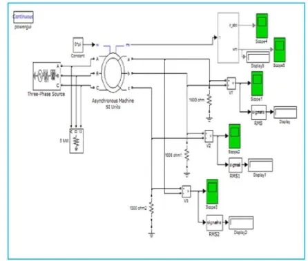
In the view of MATLAB simulink, MVFT is a type of machine which can be simulated with the asynchronous machine SI units. The asynchronous machine
SI units having a three-phase excitation system on stator side. The constant speed achieved from dc shunt motor is simulated by using a constant block. And then we could use this simulated model, as shown as Figure 3, to solve electric system of MVFT.
Figure 1. MATLAB Simulation diagram of MVFT
B. Simulation Figures and Results
Fig. 2: The direction of rotation of rotor is same as that of the air gap field
When the rotational speed of dc shunt motor is equal to the synchronous speed i.e. relative speed is zero.
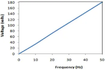
In this way we can control output voltage from zero volts to rated voltage and frequency from zero Hertz to rated frequency i.e. 50 Hz in India. The emf induced across the rotor winding versus its frequency graph achieved is shown as:
Fig.3: The direction of rotation of rotor is opposite to the air gap field
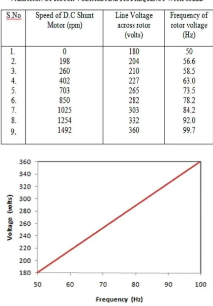
When the rotational speed of dc shunt motor is equal to the synchronous speed i.e. relative speed is double of synchronous speed.
In this way we can control output voltage from rated voltage to twice of rated voltage and frequency from rated frequency to twice the rated frequency i.e. 50 –100 Hz in India. The emf induced across the rotor winding versus its frequency graph achieved is shown as:
Figure 4. MATLAB Simulation results showing variation of rotor circuit voltages with time and voltage versus frequency graphs.
Table 1: Mechanical and electrical parameters
used during experiment.
in shunt winding and as a result the flux of dc shunt winding varies, resulting in variation of speed of dc shunt motor. Since the rotor of dc shunt motor is mechanically coupled with the rotor of induction motor, thus the speed of the induction motor varies accordingly. The voltage induced across the rotor winding and its frequency is given in the table:
a) The direction of rotation of rotor is same
as that of the air gap field:-
IV. PRACTICAL ANALYSIS
Table 2: showing the variation of rotor voltage with its frequency of table I.
Figure 5. Voltage versus Frequency curve (table I)
a) The direction of rotation of rotor is
opposite to theair gap field:-
Figure 6 shows the variation of rotor voltage with its frequency of table II.
V. CONCLUSION
over conventional phase angle regulating transformers and does not inherently produce harmonics in case of many HVDC and FACTS technologies.
Reference
[1]Arezki Merkhouf, Pierre Doyon and
Sanjoy Upadhyay, ―Variable Frequency
Transformer—Concept and
Electromagnetic Design Evaluation,
IEEE Transactions on Energy Conversion, vol. 23, no. 4, December 2008, pp. 989-996.
[2]J. J. Marczewski, ―VFT Applications
Between Grid Control Areas, IEEE PES
General Meeting, Tampa, FL, June 2007, pp. 1-4.
[3]E. Larsen, R. Piwko, D. McLaren, D.
McNabb, M. Granger, M. Dusseault, L-P. Rollin, J. Primeau, "Variable Frequency Transformer - A New Alternative for
Asynchronous Power Transfer," Canada
Power, Toronto, Ontario, Canada, September 28-30,2004.
[4]P. Doyon, D. McLaren, M. White, Y .Li,
P. Truman, E. Larsen, C. Wegner, E. Pratico, R. Piwko, "Development of a 100 MW Variable Frequency Transformer,"
Canada Power, Toronto, Ontario, Canada, September 28-30, 2004.
[5]M. Dusseault, J. M. Gagnon, D. Galibois,
M. Granger, D. McNabb, D. Nadeau, J. Primeau, S. Fiset, E. Larsen, G. Drobniak, I. McIntyre, E. Pratico, C. Wegner, "First VFT Application and Commissioning,"
Canada Power, Toronto, Ontario, CANADA, September 28-30, 2004.
[6]E.Larsen, R.Piwko, D.McLaren,
D.McNabb,
M.Granger,M.Dusseault,L-P.Rollin, J.Primeau,
“Variable-FrequencyTransformer - A New
Alternative for Asynchronous Power
Transfer,” Canada Power,
Toronto,Ontario, Canada, September 28-30,2004.
[7]P.Doyon, D.McLaren, M.White, Y.Li,
P.Truman, E.Larsen,C.Wegner, E.Pratico, R.Piwko, “Development of a 100 MW Variable Frequency Transformer,” Canada
Power, Toronto, Ontario, Canada,
September 28-30, 2004.
[8]M. Dusseault, J.M.Gagnon, D.Galibois,
M.Granger, D.McNabb, D.Nadeau, J. Primeau, S.Fiset, E.Larsen,G.Drobniak, I.McIntyre, E.Pratico, C.Wegner, “First VFT Application and Commissioning,”
Canada Power, Toronto, Ontario,
CANADA, September 28-30, 2004.
[9]D. McLaren, J. Michalec, “The Variable
Frequency Transformer(VFT) A Rotating Machine”. GE Energy and American Electric Power (AEP) Doble, 2006.
[10] A. Merkhouf, S. Upadhyay and P.
Doyon, “Variable frequency transformer - an overview”, in Proc. of the 2006 IEEE
Power Engineering Society General
Meeting, June 18-22, 2006 pp.
[11] Gesong Chen, and Xiaoxin Zhou,
“Digital Simulation of Variable Frequency
Transformers For Asynchronous
Interconnection in Power System,” 2005.
[12] Arezki Merkhouf, Pierre Doyon
and Sanjoy Upadhyay,“Variable