A Review of Maximum Power Extraction Techniques For Wind
Energy Conversion Systems
N.ManonmaniP
1
P
and P.KausalyadeviP
2
P
P
1
P
Department of EEE, Anna University/Sri Krishna College of Engineering and Technology, Coimbatore-641038, Tamil Nadu, India
P
2
P
Department of EEE, Anna University/Sri Krishna College of Engineering and Technology, Coimbatore-641038, Tamil Nadu, India
Abstract
Wind power generation involves extraction of energy from the wind by use of a wind turbine generator. Wind power generated is dependent on various factors which are controllable and uncontrollable. Techniques are developed to extract maximum power from the wind available, thus ensuring that for any given wind speed, the wind turbine is able to produce the maximum power. A review of various approaches utilized and an analysis of the strengths and weaknesses of each technique is presented in this paper.
keyterms- MPPT, wind energy conversions, maximum power.
1. Introduction
The wind energy that can be extracted from renewable energy sources like Wind Energy Conversion Systems (WECS) varies throughout the day and it is also dependent on the geographical location. For a particular wind velocity (for WECS) there is always a peak point at which maximum power can be obtained. The output power of wind turbine depends upon the accuracy at which peak power points are tracked by the implementation of a Maximum Power Point Tracking (MPPT) control techniques.
The output power from WECS is a function of rotor speed that changes with the variation of wind speed. There is always an optimum rotor speed (ωropt) for WECS for a particular wind speed at which maximum power can be extracted out of the system. The location of the Maximum Power Point (MPP) is unknown but can be located, either through calculations or through search algorithm techniques.
2. Different mppt control algorithms for
wind energy conversion systems
Wind availability is changeable and unpredictable; it is desirable to develop fast and efficient methods to track the optimal operation points of a variable speed wind energy conversion system (WES). Many methods have been proposed and discussed in this paper [1] [2] [3] [4] [5]. This paper will discuss methods that pertain to variable speed wind energy systems.
MPPT techniques are divided into two broad categories:
• Techniques that use known turbine
characteristics
•
Techniques without knowledge of turbine characteristics that allow optimization2.1 Tip Speed Ratio Control (TSR):
The amount of power produced by a wind turbine is expressed as
(1) where p is air density A is the cross sectional area of turbine V is wind velocity. The coefficient of power (cp) is a value dependent on the ratio between the turbine rotor’s angular velocity, (ωT ) and wind speed (V). This ratio is known as the Tip speed ratio (TSR),
TSR is given by:
(2)
The methods in [1] are based on the principle of loading the characteristics of wind turbine to ensure that the maximum available energy from the wind is obtained. The two methods in [1] utilize the turbine characteristics (power coefficient, torque and power curves) to determine the point that results in maximum power capture.
The only difference between the two methods presented in [1] is that one calculates the wind speed using electrical parameters while the second method requires an anemometer so that the wind speed is
physically measured. These methods are
advantageous in determining fast optimum point and implementation is easy since all the physical characteristics of the turbine are directly programmed and optimum operation point is determined by examining simply the characteristics. A disadvantage of these strategies is that they are customized for a particular turbine.
since for all its calculations assumes a certain value. The air density plays an important part in the
aerodynamics of the turbine, and thus it affects the accuracy of the turbine characteristics which are pre-programmed.
Figure 2.1 Tip Speed ratio control of WECS
2.2 Optimum Control Technique:
A maximum power point algorithm proposed in [2] uses a maximum efficiency control and a maximum torque control to get the turbine output power maximum. Based on the selected turbine characteristics, the relationship between the optimum generator torque and the generator speed is calculated. The behavior of the maximum torque control is determined by this relationship. The generator torque balances the mechanical torque so that they will be equivalent at the optimum operating point for any particular wind speed. Since the optimum torque curve is tracked such that the generator torque is controlled.
An advantage of this method is that it does not need a wind speed detector. A drawback of this method is that to select the proportional constant that describes the relationship between the generator torque and speed which is again based on the turbine characteristics. This dependency hinders the ability to be used for various wind turbines, since different turbines have different turbine Characteristics.
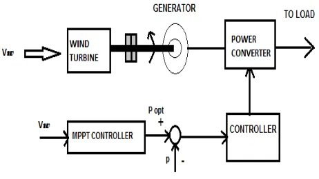
2.3 Power Signal Feedback (PSF) Control:
The proposed algorithm in [5] searches for the peak power by changing the speed reference in an appropriate direction. The speed reference is modified towards it optimal operating point depending on the magnitude and direction of change in active power. The peak power points are identified on the power versus generator shaft speed curve where its derivative is equal to zero; the power curve looks similar to that of inverse parabola
.
Pout=Kopt* ω^3 (3)
In [5], the output power and wind speed are sampled at regular time intervals. If difference in the wind velocity is maintained stable then the system was originally at its optimum point, then no action should be taken. When there is a change in wind velocity, then the turbine is no longer operating at its optimum point and that will result in a corresponding change in power. Positive change in power corresponds to an increased speed reference proportional to the change in power, and a negative change of power corresponds to a decreased speed reference. For further adjustment (when wind speed is stable) the speed reference direction can be determined by both the power change and the previous reference speed direction. For example, if a reduced speed reference results in a positive change in power then the system will continue to reduce the speed reference. When the change in power is minimal (within a predefined limit) then no further change in the speed reference is done (since the minimal change in power translates to the maximum power point).
Figure 2.2: power signal feedback control for WECS
A disadvantage of this algorithm is that it uses the turbine characteristics (power coefficient, torque, power curves) to determine the amount of change in the reference speed with respect to change in power.
This introduces dependency of the algorithm to the characteristics of a particular turbine. Another drawback of this algorithm is that it does not have any means to store the previously determined maximum power operating points. This means that with each change in wind speed, the algorithm have to search for the optimum point even if it has been determined previously. This repetitiveness of the searching procedure will slow down the optimum point determination process and cause subsequent losses in potential output power.
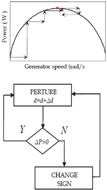
2.4 Hill-Climb Search (HCS) Control:
The HCS control algorithm continuously searches for the maximum power of the wind turbine. It can overcome some of the common problems that are normally associated with the other two methods. The tracking algorithm depends upon the relation between the changes in power and speed, location of the operating point, computes the desired optimum signal in order to drive the system to the point of peak power. Fig. 2.3 shows the principle of HCS control and Fig. 2.4 shows a WECS with HCS controller for tracking maximum power points.
Figure 2.3:HCS Control Principle
In [4], the wind turbine is connected to a rectifier through a battery, and a DC/DC converter. The proposed MPPT algorithm adjusts the operating point of the wind energy conversion system by directly adjusting the duty cycle of DC/DC converter based on the comparisons of the output power measurements. The basis of the algorithm is very similar to that of the Hill Climb Search (HCS) method as proposed by [3], [5]. The distinctive feature is that the adjustments are implemented through a ratio of the change in output power to the duty ratio. Relationships between the duty ratios of the boost, buck-boost, and buck converters and the change in output power have been described in [4]. Thus, the algorithm determines the operation point adjustment based on the change in power with respect to the duty cycle of the converter.
Figure 2.4: WECS with hill climb search control
2.5 Advanced Hill Climb Search (AHCS):
The method in [3] is an Advanced Hill Climb Search (AHCS) uses the principle of search-remember-reuse technique. The method uses intelligent memory for storing peak power points, obtained during the training process, which are later used for tracking peak power points. The principle behind this algorithm is a search-remember-reuse technique. The algorithm will start with a relatively poor initial performance from an empty intelligent memory. During execution, training mode to gradually train the intelligent memory to record the training experience will use the searched data by advanced hill-climb search. For fast execution the algorithm will reuse the recorded data in application mode. This
remember- reuse” technique will repeat itself until an accurate memory of system characteristics has been established.
Therefore, after the algorithm is adequately trained, its maximum power extraction performance is optimized. Since the intelligent memory is trained by on-line during system operation, this process is also referred as on-line Training process.
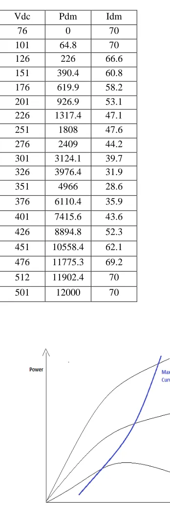
Figure 2.5: a) Intelligent Memory Lookup Table ; b)Power characteristic of turbine with respect to
Vdc[3].
There are three basic modes in this method, i) initial mode, ii) training mode, and iii) application mode.
Before the algorithm has been trained, during its initial mode, by the max-power error driven (MPED) control, the magnitude of Idm is determined. MPED control is the implementation of the conventional hill climb search (HCS) method in terms of wind energy system turbine characteristics. The algorithm continually records and updates the operating parameters into its programmable lookup table for its intelligent memory feature during its training mode. It allows itself to adapt to a turbine, since this method is trainable with its intelligent memory. As a result, it is a solution to the customization problems for many algorithms. It does not require a mechanical sensor (like anemometers) which lowers its cost and eliminates its associated practical issues is an advantage of this algorithm. However, it can be seen in [3] that the algorithm is relatively complex and slow as it has three different modes of operation.
Figure 2.6:Structure of advanced hill climb control
Another disadvantage is that the algorithm cannot take into account of the changes due to air density, which affects the power characteristics curve quite significantly [4]. Due to fluctuations in air density its look up table updating process will be adversely affected. The updating method in [7] states that the
Vdc Pdm Idm
76 0 70
101 64.8 70
126 226 66.6
151 390.4 60.8
176 619.9 58.2
201 926.9 53.1
226 1317.4 47.1
251 1808 47.6
276 2409 44.2
301 3124.1 39.7
326 3976.4 31.9
351 4966 28.6
376 6110.4 35.9
401 7415.6 43.6
426 8894.8 52.3
451 10558.4 62.1
476 11775.3 69.2
512 11902.4 70
501 12000 70
look up table, which constitutes its intelligent memory feature, which is updated when these three particular conditions are met. The conditions are i) that the system should be in steady state (wind speed must be stable),ii) that the system should operate in the down-hill region of the power curve, and iii) that the current output power (Pout) should be greater than the recorded demanded output power (Pdm) for a particular wind speed Vdc. Figure 2.5a) is an example of the intelligent memory look up table used in [7]. Figure 2.5b) is the power characteristic of the turbine where a particular Vdc is generated by the generator that corresponds to a particular generator speed. If the measured Pout, provides the conditions i), ii) and iii) are met, is greater than the Pdm, then the corresponding Vdc nearest to the current Vdc, will be replaced with the new Vdc, Pout and Idm ( demanded current that provides the new Pout) values. If the air density is maintained constant then the algorithm can effectively determine the maximum power curve as shown in Figure 2.5b.
However, with the changing air densities, it can be seen that the Maximum power curve shifts with a change in air density. With the updating rules in [3], the highest Pout value for a particular velocity, Vdc in the downhill region of the power curve represents the optimal peak power point. Ultimately, the maximum power curve will be for the highest air density conditions and thus inaccurate for lower air density.
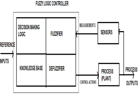
2.6 Fuzzy Logic Control In MPPT
Fuzzy Logic Control in MPPT allows the control of systems whose parameters are incomplete, unknown or vague since it is a powerful tool and as a result, are difficult to model mathematically. Fuzzy Logic Control consists of three main stages: input stage, processing stage and output stage. Membership functions are used to fuzzify the input values, at the input stage. The fuzzified input from the input stage is fed into the processing stage where an inference mechanism is applied based on the appropriate rule(s) from the knowledge base to come up with a set of fuzzy outputs. In the output stage, this output is defuzzified using an appropriate technique. The result is a control output which can be applied to the process or plant being controlled. This is illustrated in the block diagram shown in Fig.2.5 Fuzzification process involves use of linguistic variables to describe the actual input and output values which are being fuzzified, and generated to degrees of membership in the form of membership functions.
A typical MPPT requires membership functions for inputs such as change in wind power output, wind
turbine rotor speed and change in wind speed, where an anemometer is one of the sensors... The expected outputs from the system, such as adjustment in rotor speed, are also expressed in the terms of Fuzzy variables. The number of membership functions depends upon the number of variables that are being measured, and this in turn affects the number of sensors required by the wind turbine system.
Figure 2.6: Fuzzy control block diagram
2.7 Neural Network Based Controllers
A wind speed estimation based on neural network for TSR control is proposed in [6] in order to track the maximum power points. Using neural networks, the wind speed is estimated and further by using the estimated wind speed and knowledge of optimal Tip speed ratio the optimal rotor speed command is estimated. The generated optimal speed command is given to the speed control loop of the Wind Energy control system. The actual rotor speed is controlled by the PI controller to the desired value by changing the switching ratio of the PWM inverter. The control target of the inverter is the output power delivered to the load. The block diagram of the ANN-based MPPT controller module is shown in Fig.2.7. The inputs given to the ANN are mechanical power Pm and the rotor speed ωr. The Pm is obtained using the relation
Pm= ωr(J+d ωr/dt) +Pe
(4)Figure 2.7: Neural network control block diagram
2.8 Adaptive Neuro Fuzzy Controllers
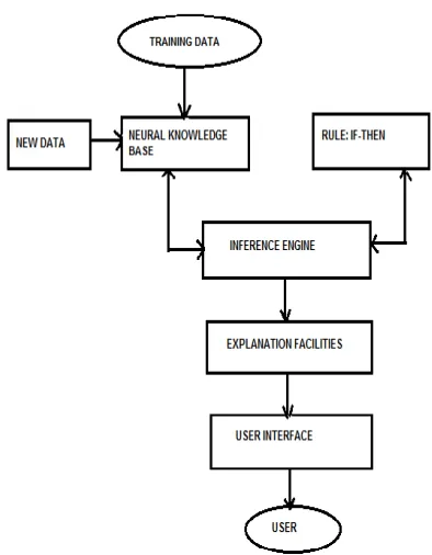
Neuro-Fuzzy Control is an advanced technique which overcomes the drawbacks of the above methods. A Neural network is used for generating and adaptively tuning the Fuzzy rules for matching the operating conditions of the system until the controller operates at maximum efficiency. The basic structure of a neural network system is shown in Fig. 2.8. Adaptive Neuro Fuzzy Inference Systems (ANFIS) combine the strengths of Neural Networks and Fuzzy Logic controllers to create systems capable of controlling the complex systems and for adaptively learning to optimize the control parameters.
Figure 2.8: Neural-fuzzy control block diagram
The ANFIS structure is composed of several layers Layer 1 is used for the input layer which directly transfers each crisp input into the next layer. Layer 2 is used as the fuzzification layer that converts each crisp input into a fuzzy input based on the membership functions which are related to that input. In this layer, each fuzzy set is represented as a neuron, and the activation function of that particular neuron is set to a triangular membership function corresponding to that relevant input. Layer 3 is used as the Fuzzy Rule Layer, and in this layer each neuron corresponds to a single Fuzzy Rule from the Rule base system. Layer 4 is used as the output layer. In this layer each neuron is represented by a fuzzy set used as a consequent for fuzzy rules. Each neuron output represents the firing strength of the particular fuzzy set. Layer 5 is used as the defuzzification layer. It combines the signals from layer 4, weighted according to their respective firing strengths into a Single crisp output which acts as an output of Adaptive Neuro Fuzzy Inference Systems (ANFIS). In [7] they employ a back propagation learning algorithm for neural with Modified Particle Swarm Optimization technique(MPSO).
2.9 SUMMARY OF MPPT ALGORITHMS
The methods in [3], [4], and [5] use the changes in power (P) and the changes in generator speed (w) to adjust the generator speed towards the optimum operating point. The intelligent memory in [3] allows the algorithm to be more efficient over time as the optimal points are stored, when determined, for later usage. The methods in [3],[4], and [5] are independent of turbine characteristics, hence they are flexible and can be applied to various turbine systems. These algorithms, however, would be slower than those in [1] and [2] because of their adjustment process. The algorithms described in [2] and [1] are fast and efficient, but they are dependent on having prior knowledge of the turbine characteristics. Therefore the methods in [2] and [1] cannot be used for a wide range of turbines and cannot consider machine degradation since they cannot adapt to change in wind speed.
3. CONCLUSION
Maximum Power Point Tracking is an important technique for efficiently harnessing the wind power. Selection of the right control strategy is significant to ensure that the system performs optimally. Techniques based upon the knowledge of wind
turbine characteristics, that is, Torque, Speed and Power Signal Feedback based methods provide a simple way of obtaining maximum wind power where the manufacturer or by experimentation, the turbine characteristics have been provided. This method offers a fairly cost-effective solution. Controller software and hardware requirements are simple, and specialized knowledge does not require for the actual controller design. Fuzzy Logic based and Neuro-Fuzzy controllers give a greater flexibility to the controller design as the prior knowledge of the turbine characteristics is not necessary known. Reliability on sensors is reduced. Further the Neuro-Fuzzy controller does not require an expert knowledge since the learning algorithm adaptively tunes the controller for an optimum performance. Research in the area of Maximum power point tracking techniques has resulted in several alternatives routes for the user of the wind turbine for maximum power generation. However, in general, research has omitted turbulence of wind as a factor in controller design.
References:
[1] G. Moor and H. Beukes, “Power point trackers for wind turbines,” Power Electronics Specialist Conference (PESC), pp. 2044–2049, 2004.
[2] T. Nakamura, S. Morimoto, M. Sanada, and Y. Takeda, “Optimum control of PMSG for wind generation system,” Power Conversion Conference (PCC), vol. 3, pp. 1435– 1440, 2008.
[3] Q. Wang and L.-C. Chang, “An intelligent maximum power extraction algorithm for inverter-based variable speed wind turbine systems,” IEEE Transactions on Power Electronics, vol. 19, pp. 1242–1249, September 2004.
[4] E. Koutroulis and K. Kalaitzakis, “Design of a maximum power tracking system for wind-energy-conversion applications,” IEEE Transactions on Industrial Electronics, vol. 53, April 2006.
[5] R. Datta and V.-T.Ranganathan, “A method of tracking the peak power points for a variable speed wind energy conversion system,” IEEE Transactions on Energy Conversion, vol. 18, pp. 163–168, March 2003.
[6] H. Li, K. L. Shi and P. G. McLaren, “Neural-network-based sensorless maximum wind energy capture with compensated power coefficient,” IEEE Trans. Ind. Appl., vol. 41, no. 6, pp. 1548-1556, Nov./Dec. 2005.
[7] Galdi V., Piccolo A. and Siano P., “Designing an adaptive fuzzy controller for maximum wind energy extraction,” IEEE Transactions on Energy Conversion, vol. 2, pp. 559–569, 2008
[8] O. T. L. K. Lin W., Hong C. and H. C., “An intelligent maximum power tracking control strategy for wind-driven ig system using mpso algorithm,” in 2009 IEEE/ASME International Conference on Advanced Intelligent Mechatronics, 2009.
[9] Mirecki A., Roboam X. and Richardeau F., “Comparative study of maximum power strategy in wind turbines,” IEEE Transactions on Energy Conversion, pp. 993–998, 2004.
N.Manonmani ME (Power Systems) – 2004, Ph.D (pursuing) on Renewable Energy Systems. Area of interest includes Power System Analysis, Protection & Switchgear, Power System Operation and Control, Transmission and Distribution, Renewable Energy Sources, Wind Energy Conversion System
P.Kausalyadevi BE (EEE) - 2013, ME (Pursuing) (Power Electronics and drives) . Area of interest includes Power Electronics AC drives, DC Drives, Wind energy conversion systems, Renewable Energy Sources, Protection and Switchgear, Power System Operation and Control