Design and Thermal Analysis of Combustion Outer Case
for Turbo Engine
ABSTRACT
A turbocharger or turbo is a gas compressor that uses the turbine driven forced induction device that increases an engine’s efficiency and power by forcing extra air into the combustion chamber. A turbocharger has the compressor powered by a turbine. The turbine is driven by the exhaust gas from the engine. It does not use a direct mechanical drive. This helps improve the performance of the turbocharger. The main problems with the turbo charger are oil leakage, damage of blades, whistling, sluggish, and outer case compression problem to overcome this problem many of the peoples work on the problem and they came out with new solutions to it. The objective of this project is to be design the outer case of a turbocharger for a diesel engine to increase its power and efficiency, and showing the advantage of designing of a turbocharger. The project tends to usage of new materials is required. In the present work impeller was designed
with three different materials. The investigation can be done by using Creo-2 and ANSYS software. The Creo-2 is used for modeling the impeller and analysis is done in ANSYS .ANSYS is dedicated finite element package used for determining the variation of stresses, strains and deformation across profile of the impeller.
INTRODUCTION
Internal Combustion Engine
The internal combustion engine is the powerhouse of a variety of machines and equipment ranging from small lawn equipment to large aircraft or boats. Given the focus of this paper, the most important machine powered by an internal combustion engine is the automobile. The engine literally provides the driving force of the car while also directly or indirectly powering just about every other mechanical and electrical system in the modern automobile. While there are several types of internal Dhondi Sindhuja
M.Tech (Thermal engineering), P.G. Scholar
Nishitha College of engineering and technology
Rangdal Srikanth Mtech(AMS), Asst professor
combustion engines that cover the aforementioned large range of applications, they all basically do the same thing.
They all convert the chemical energy stored in a fuel of some kind into mechanical energy, which can then be converted into electrical energy. The three most common types of internal combustion are the 4-stroke gasoline engine, the 2-stroke gasoline engine, and the diesel engine. A brief description of each the common types of internal combustion engine are provided below.
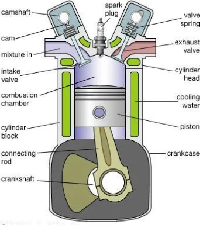
The 4-stroke gasoline engine is the most frequently used engine in cars and light trucks as well as in large boats and small aircraft. The major components of the cylinder of a 4-stroke gasoline engine. While the arrangement and number of the cylinders in an engine tends to vary, the parts that
make up an individual cylinder remain pretty constant. The most significant component is the piston which is connected to the crankshaft via a connecting rod. The motions of the piston and crankshaft are always related, with one always forcing the other to move. The two valves, intake and exhaust, at the top of the cylinder are opened and closed by separate camshafts that precisely control the timing of each valve’s movement. The spark plug at the top of the cylinder is powered by the engine battery and activated by the engine computer at the appropriate time. Finally, the entire cylinder is surrounded by coolant channels that run through the engine block to remove the massive amount of heat generated by the running engine.
Figure 1 Components of a 4-stroke gasoline engine cylinder.
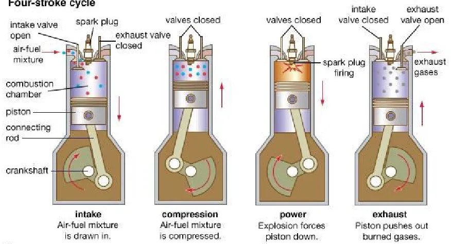
The four strokes of a 4-stroke gasoline engine, illustrated in Fig. 1.2, are intake, compression, power and exhaust. During the intake stroke, the camshaft opens the intake
camshaft closes the intake valve. The piston
is now at what is known as bottom dead center, and the cylinder is completely filled with the air/fuel mixture.
Figure 2 Engine cycle of a 4-stroke gasoline engine.
The compression stroke comes next. With both intake and exhaust valves closed, the crankshaft raises the piston, compressing the air/fuel mixture. When the piston has been raised to the top of the cylinder, it is said to be at top dead center. Once the cylinder has reached top dead center, the air/fuel mixture has been compressed as much as possible.The power stroke is next up. With the piston still at top dead center and both valves closed, the spark plug fires, igniting the compressed air/fuel mixture. Once ignited, a flame begins to move through the mixture, causing it to expand downward smoothly. This expansion downward forces the piston to move down. This means that the piston is rotating to the crankshaft, whereas the rotation of the crankshaft moves the piston in the other three strokes. The fact that the piston is driving the crankshaft means that energy is being transferred to the crankshaft. This is how an internal
larger application because they are less efficient and dirtier than their 4-stroke counterparts. Aside from having fewer strokes, 2-stroke engines differ from 4-stroke
engines in their fuel mixtures and cylinder components. The two strokes, upstroke and downstroke, of a 2-stroke engine along with the cylinder setup.
Figure 3 Engine cycle of a 2-stroke gasoline engine. There are no camshafts or complicated valve
trains involved here, meaning the piston basically has to perform more diverse functions that in 4-stroke engines. Furthermore, special two cycle oil is mixed in with the gasoline to help lubricate the piston, so the air/fuel mixture in a 2-stroke engine includes oil. When the piston is at the bottom of the cylinder, the already compressed air/fuel mixture has moved via the transfer port into the top of the cylinder. On the upstroke, the piston further compresses the air/fuel mixture, creates a vacuum in the crankcase and uncovers the intake port. The vacuum opens the intake valve and draws more air/fuel mixture into the crankcase. The spark plug fires and ignites the mixture, which forces the piston down just like in the 4-stroke cycle. On the down stroke, the piston transfers energy to the crankshaft while compressing the air/fuel mixture in the crankcase and uncovering the exhaust port. As the piston reaches the bottom of the cylinder, the compressed air/fuel mixture is again forced into the top of the cylinder via the transfer port, which forces the remaining exhaust out of the
transferring energy to the crankshaft. The power stroke is complete when the piston reaches bottom dead center. During the exhaust stroke, the crankshaft raises the piston, forcing the exhaust gases out of the now open exhaust valve. Once the piston reaches top dead center, the cycle is ready to begin again.
Turbochargers
As stated in the previous section, a turbocharger is a device that uses engine exhaust gases to power a compressor that increases the pressure of the air entering the engine, which results in more power from the engine. Air enters the compressor from
the left, is compressed and then directed to the intake valve of the cylinder. Exhaust exits the exhaust valve of the cylinder, spins the turbine and is expelled. The three major pieces of a turbocharger introduced in the previous section and shown in Fig. 1.6 are the compressor, bearings section and turbine. Each of these sections has an important function and deserves further attention. It is also important to recognize in any discussion of turbo charging that turbo charging an engine involves more than just slapping a turbocharger on to the engine. An entire system must be developed for the turbocharger, including a means of temperature and pressure control.
Figure 4: Simplified drawing of turbocharger and engine cylinder.
Turbocharger as a Device
Before getting into the details of a turbocharged system, the turbocharger as a device will be described in more detail. It effectively illustrates the relationship between the three sections as well as the input and output of each section. The heart of the turbocharger is the assembly of compressor blades, shaft and turbine blades. It is this assembly that rotates at over a 100000 RPM when the turbocharger is
operational. This assembly also serves as the common connection between the three major components of the turbocharger, which otherwise are independent of each other.
housing, respectively. The role of the compressor housing is to direct ambient air axially into the spinning compressor blades. The blades and housing are designed together such that the ambient air is compressed and forced into the air channel wrapped around the center of the compressor housing, which expels the compressed air tangentially. The compressed air leaves the compressor with higher pressure and temperature. The pressure increase across the compressor is known as boost. For example, if ambient air enters the compressor at atmospheric pressure (14.7psi) and leaves at a pressure of 19.7psi, the turbocharger is said to be creating 5psi of boost. Generally speaking, the higher the boost pressure, the higher the power gains but more difficulty and cost are involved in developing the system. The compressor works best at a particular combination of airflow and boost pressure. The compressor should be chosen wisely to ensure most efficient operation. The primary function of the bearings housing is to guide the rotating shaft connecting the compressor and turbine blades. This shaft is guided using either journal or ball bearings. The bearings housing has a secondary function of lubricating the shaft and bearings. This is accomplished by routing engine oil into the bearings housing, which distributes the oil around the shaft and bearings. The oil is then drained out of the bearings section at which point it can be returned to the engine. Heat from the exhaust gases can lead to oil coking, the charring of the oil on to the oil channels. This restricts oil flow and eventually destroys the bearings. Some bearings sections have water jackets that allow engine coolant to reduce the temperature of the oil.
The main function of the turbine housing is to direct exhaust gases to the turbine blades to accelerate them as quickly as possible.
Exhaust gas enters the turbine housing tangentially and travels through the channels surrounding the center of the turbine. These channels lead the air into the turbine blades, forcing them to rotate. The exhaust is then expelled from the turbine housing axially. The size of the turbine housing has a significant impact on the behavior of the turbine. In particular, changing the size of the turbine effects turbocharger response, power gains and the engine speed at which the turbocharger is most effective.
Turbocharger as a System
the compressor from adding heat to the air as it compresses it, though the amount of heat added can be limited by choosing a properly sized compressor. It is undesirable to just allow the hot intake air to go straight to the engine as it can reduce power gains and lead to engine knocking. An intercooler is thus included in the system to remove the heat added by the compressor. The heat is removed via cross flow of a cooling fluid, either air or water. The air is then free to flow to the engine with a lower temperature but still higher than atmospheric pressure.
The concept of boost was introduced in the previous section as was the relationship between boost and the system. That is to say that while higher boost generally leads to higher power it also leads to increasingly complicated and expensive system requirements. Since a turbocharged system is rarely designed with unlimited budget and design freedom, there will always be a maximum boost that the system is designed to accommodate. This maximum boost is usually chosen based on performance goals, and the system is then designed specifically for that boost pressure. If this maximum boost pressure is exceeded, the system could very likely fail, resulting in damage to the turbocharger or engine. If left unchecked though, the turbocharger will continue to create boost well past the maximum boost pressure. A boost control system is thus added to limit the boost created by the turbocharger. A waste gate works by bleeding exhaust gas away from the turbine once the maximum boost pressure is
reached. As less exhaust reaches the turbine, the turbocharger slows down and creates less boost pressure.
The exhaust system consists of everything from the engine exhaust ports to the tailpipe. This includes the manifold, turbine, waste gate and the muffler. The job of the exhaust system is to connect and support all of these components with pipes. The design of the exhaust manifold, including the primaries and merge collectors, is considered part of the exhaust system. The final major system component is the lubrication system for the turbocharger bearings. In the drawing, this system consists of an oil feed line and an oil drain line between the turbocharger bearings and the engine. The oil feed line is connected to the engine at a location with positive oil pressure, and the oil drain line is connected to the engine’s oil pan. More complicated systems including dedicated pumps and oil reserves are not uncommon. The coolant lines between the turbocharger bearings and the engine’s radiator circuit are not included in the figure as water jackets are not available on all turbochargers and thus are not considered to be standard. In addition to these components, any high boost turbocharged system is going to require modifications to various engine parts. Electrical and ignition systems may need to be upgraded to ensure proper ignition. The fuel injection systems may need to be upgraded to maintain the correct AFR. The throttle bodies and valve train may need to be changed to provide for proper flow conditions
.
Output range (hp) 100 to 310 Airflow (max) 0.46 kg/s Length (mm) 250 Width (mm) 240 Height (mm) 220 Mass (kg) 16 to 17
Turbo outer Casing stress analysis
Stain less steel CF8C plus cast stain less steel
HK30Nb stainless alloy
Density 7.96 7.81
Ductility 0.32 0.34
Elastic limit 209MPA 207MPA
Thermal conductivity 14.54w/mk 15.23w/mk
Heat input 350ºc 350ºc
A modal analysis is typically used to determine the vibration characteristics (natural frequencies and mode shapes) of a structure or a machine component while it is being designed. It can also serve as a starting point for another, more detailed, dynamic analysis, such as a harmonic response or full transient dynamic analysis.Modal analyses, while being one of the most basic dynamic analysis types available in ANSYS, can also be more computationally time consuming than a typical static analysis. A reduced solver, utilizing automatically or manually selected master degrees of freedom is used to
drastically reduce the problem size and solution time.
HARMONIC ANALYSIS
Used extensively by companies who produce rotating machinery, ANSYS Harmonic analysis is used to predict the sustained dynamic behavior of structures to consistent cyclic loading. A harmonic analysis can be used to verify whether or not a machine design will successfully overcome resonance, fatigue, and other harmful effects
of forced vibrations
.
THERMAL ANALYSIS OF TUBO CASING
Material Properties:
Stain less steel HK30Nb stainless alloy
Density 7.81
Elastic limit 207MPA
Thermal conductivity 15.23w/mk
Heat input 350ºc
Units:
TABLE 1
Unit System Metric (mm, kg, N, s, mV, mA) Degrees rad/s Celsius
Angle Degrees
Rotational Velocity rad/s
Temperature Celsius
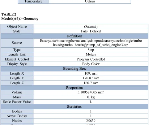
TABLE 2
Model (A4) > Geometry
Object Name Geometry
State Fully Defined
Definition
Source E:\sanya\turbocasingthermalanalysisinputdatasanyatechnologie\turbo housing\turbo housing\pump_of_turbo_engine3.stp
Type Step
Length Unit Meters
Element Control Program Controlled
Display Style Body Color
Bounding Box
Length X 109. mm
Length Y 170.87 mm
Length Z 160.7 mm
Properties
Volume 5.1095e+005 mm³
Mass 0. kg
Scale Factor Value 1.
Statistics
Bodies 1
Active Bodies 1
Nodes 25639
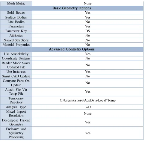
Mesh Metric None Basic Geometry Options
Solid Bodies Yes
Surface Bodies Yes
Line Bodies No
Parameters Yes
Parameter Key DS
Attributes No
Named Selections No
Material Properties No
Advanced Geometry Options
Use Associativity Yes
Coordinate Systems No
Reader Mode Saves
Updated File No
Use Instances Yes
Smart CAD Update No
Compare Parts On
Update No
Attach File Via
Temp File Yes
Temporary
Directory C:\Users\kishore\AppData\Local\Temp
Analysis Type 3-D
Mixed Import
Resolution None
Decompose Disjoint
Geometry Yes
Enclosure and Symmetry
Processing Yes
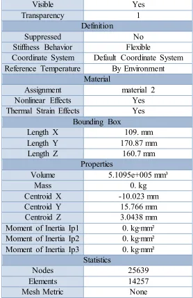
TABLE 3: Model (A4) > Geometry > Parts
Object Name PUMP_OF_TURBO_ENGINE
State Meshed
Visible Yes
Transparency 1
Definition
Suppressed No
Stiffness Behavior Flexible
Coordinate System Default Coordinate System Reference Temperature By Environment
Material
Assignment material 2
Nonlinear Effects Yes
Thermal Strain Effects Yes Bounding Box
Length X 109. mm
Length Y 170.87 mm
Length Z 160.7 mm
Properties
Volume 5.1095e+005 mm³
Mass 0. kg
Centroid X -10.023 mm
Centroid Y 15.766 mm
Centroid Z 3.0438 mm
Moment of Inertia Ip1 0. kg·mm² Moment of Inertia Ip2 0. kg·mm² Moment of Inertia Ip3 0. kg·mm²
Statistics
Nodes 25639
Elements 14257
Mesh Metric None
Coordinate System:
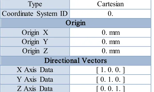
TABLE 4: Model (A4) > Coordinate Systems > Coordinate System
Object Name Global Coordinate System
State Fully Defined
Type Cartesian Coordinate System ID 0.
Origin
Origin X 0. mm
Origin Y 0. mm
Origin Z 0. mm
Directional Vectors X Axis Data [ 1. 0. 0. ] Y Axis Data [ 0. 1. 0. ] Z Axis Data [ 0. 0. 1. ]
TABLE 5: Model (A4) > Mesh
Object Name Mesh
State Solved
Defaults
Physics Preference Mechanical
Relevance 0
Sizing
Use Advanced Size Function Off
Relevance Center Coarse
Element Size Default
Initial Size Seed Active Assembly
Smoothing Medium
Transition Fast
Span Angle Center Coarse
Minimum Edge Length 2.9763e-002 mm Inflation
Use Automatic Inflation None
Inflation Option Smooth Transition
Transition Ratio 0.272
Maximum Layers 5
Growth Rate 1.2
Inflation Algorithm Pre
View Advanced Options No
Patch Conforming Options
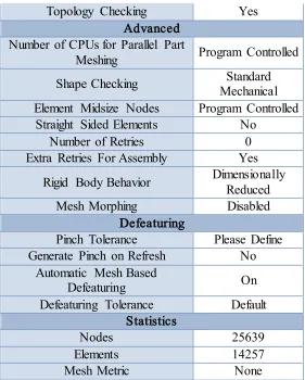
Topology Checking Yes Advanced
Number of CPUs for Parallel Part
Meshing Program Controlled
Shape Checking Mechanical Standard Element Midsize Nodes Program Controlled
Straight Sided Elements No
Number of Retries 0
Extra Retries For Assembly Yes Rigid Body Behavior Dimensionally Reduced
Mesh Morphing Disabled
Defeaturing
Pinch Tolerance Please Define Generate Pinch on Refresh No
Automatic Mesh Based
Defeaturing On
Defeaturing Tolerance Default Statistics
Nodes 25639
Elements 14257
Mesh Metric None
Steady State Thermal (A5)
TABLE 6: Model (A4) > Analysis
Object Name Steady-State Thermal (A5)
State Solved
Definition
Physics Type Thermal
Analysis Type Steady-State Solver Target Mechanical APDL
Options Generate Input
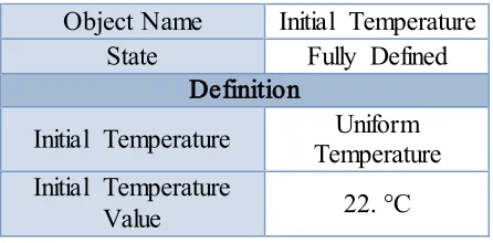
TABLE 7: Model (A4) > Steady-State Thermal (A5) > Initial Condition
Object Name Initial Temperature
State Fully Defined
Definition
Initial Temperature Temperature Uniform Initial Temperature
Value 22. °C
TABLE 8: Model (A4) > Steady-State Thermal (A5) > Analysis Settings
Object Name Analysis Settings
State Fully Defined
Step Controls
Number Of Steps 1.
Current Step
Number 1.
Step End Time 1. s
Auto Time
Stepping Program Controlled
Solver Controls
Solver Type Program Controlled
Radiosity Controls
Radiosity Solver Program Controlled
Flux Convergence 1.e-004
Maximum Iteration 1000.
Solver Tolerance 1.e-007 W/mm²
Over Relaxation 0.1
Hemicube
Resolution 10.
Nonlinear Controls
Heat Convergence Program Controlled
Convergence
Line Search Program Controlled
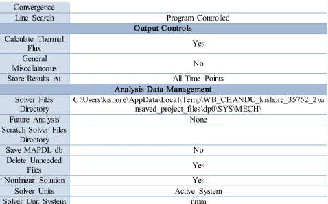
Output Controls Calculate Thermal
Flux Yes
General
Miscellaneous No
Store Results At All Time Points
Analysis Data Management Solver Files
Directory
C:\Users\kishore\AppData\Local\Temp\WB_CHANDU_kishore_35752_2\u nsaved_project_files\dp0\SYS\MECH\
Future Analysis None
Scratch Solver Files Directory
Save MAPDL db No
Delete Unneeded
Files Yes
Nonlinear Solution Yes
Solver Units Active System
Solver Unit System nmm
TABLE 9: Model (A4) > Steady-State Thermal (A5) > Loads
Object Name Temperature Convection
State Fully Defined
Scope
Scoping Method Geometry Selection
Geometry 41 Faces 1 Body
Definition
Type Temperature Convection
Magnitude 350. °C (ramped)
Suppressed No
Film Coefficient Tabular Data
Coefficient Type Average Film Temperature
Ambient Temperature 22. °C (ramped)
Convection Matrix Program Controlled
Edit Data For Film Coefficient
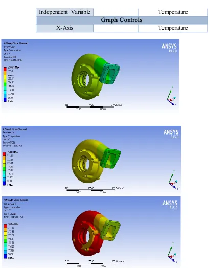
Independent Variable Temperature Graph Controls
X-Axis Temperature
TABLE 10: Model (A4) > Steady-State Thermal (A5) > Convection
Temperature [°C] Convection Coefficient [W/mm²·°C]
10. 2.05e-006
100. 4.41e-006
200. 5.56e-006
300. 6.36e-006
500. 7.54e-006
700. 8.43e-006
1000. 9.5e-006
TABLE 11: Model (A4) > Steady-State Thermal (A5) > Solution Object Name Solution (A6)
State Solved
Adaptive Mesh Refinement Max Refinement Loops 1.
Refinement Depth 2. Information
Status Done
TABLE 12: Model (A4) > Steady-State Thermal (A5) > Solution (A6) > Solution Information Object Name Information Solution
State Solved
Solution Information
Update Interval 2.5 s
Display Points All
FE Connection Visibility
Activate Visibility Yes
Display All FE Connectors
Draw Connections Attached To All Nodes Line Color Connection Type
Visible on Results No
Line Thickness Single
Display Type Lines
TABLE 13: Model (A4) > Steady-State Thermal (A5) > Solution (A6) > Results
Object Name Temperature Total Heat Flux
State Solved
Scope
Scoping Method Geometry Selection
Geometry All Bodies
Definition
Type Temperature Total Heat Flux
By Time
Display Time Last
Calculate Time History Yes
Identifier
Suppressed No
Results
Minimum 235.63 °C 2.2085e-005 W/mm²
Maximum 350.01 °C 0.13105 W/mm²
Minimum Value Over Time
Minimum 235.63 °C 2.2085e-005 W/mm²
Maximum 235.63 °C 2.2085e-005 W/mm²
Maximum Value Over Time
Minimum 350.01 °C 0.13105 W/mm²
Maximum 350.01 °C 0.13105 W/mm²
Information
Time 1. s
Substep 1
Iteration Number 3
Integration Point Results
Display Option Averaged
Average Across Bodies No
Material Data
TABLE 14: Material 1 > Constants
Thermal Conductivity 1.523e-002 W mm^-1 C^-1
Material Properties
Stain less steel CF8C plus cast stain less steel
Density 7.96
Ductility 0.32
Elastic limit 209MPA
Thermal conductivity 14.54w/mk
Heat input 350ºc
Units:
TABLE 15
Unit System Metric (mm, kg, N, s, mV, mA) Degrees rad/s Celsius
Angle Degrees
Rotational Velocity rad/s
Temperature Celsius
TABLE 16: Model (A4) > Geometry
Object Name Geometry
State Fully Defined
Definition
Source E:\sanya\turbocasingthermalanalysisinputdatasanyatechnologie\turbo housing\turbo housing\pump_of_turbo_engine3.stp
Length Unit Meters
Element Control Program Controlled
Display Style Body Color
Bounding Box
Length X 109. mm
Length Y 170.87 mm
Length Z 160.7 mm
Properties
Volume 5.1095e+005 mm³
Mass 0. kg
Scale Factor Value 1.
Statistics
Bodies 1
Active Bodies 1
Nodes 25639
Elements 14257
Mesh Metric None
Basic Geometry Options
Solid Bodies Yes
Surface Bodies Yes
Line Bodies No
Parameters Yes
Parameter Key DS
Attributes No
Named Selections No
Material Properties No
Advanced Geometry Options
Use Associativity Yes
Coordinate Systems No
Reader Mode Saves
Updated File No
Use Instances Yes
Smart CAD Update No
Compare Parts On
Update No
Attach File Via
Temp File Yes
Temporary
Directory C:\Users\kishore\AppData\Local\Temp
Mixed Import
Resolution None
Decompose Disjoint
Geometry Yes
Enclosure and Symmetry Processing
Yes
Coordinate Systems:
Steady – State Thermal (A5):
TABLE 17: Model (A4) > Analysis Object Name Steady-State Thermal (A5)
State Solved
Definition
Physics Type Thermal
Analysis Type Steady-State Solver Target Mechanical APDL
Options
Generate Input Only No
TABLE 18: Model (A4) > Steady-State Thermal (A5) > Analysis Settings
State Fully Defined Step Controls
Number Of Steps 1.
Current Step
Number 1.
Step End Time 1. s
Auto Time
Stepping Program Controlled
Solver Controls
Solver Type Program Controlled
Radiosity Controls
Radiosity Solver Program Controlled
Flux Convergence 1.e-004
Maximum Iteration 1000.
Solver Tolerance 1.e-007 W/mm²
Over Relaxation 0.1
Hemi cube
Resolution 10.
Nonlinear Controls
Heat Convergence Program Controlled
Temperature
Convergence Program Controlled
Line Search Program Controlled
Output Controls Calculate Thermal
Flux Yes
General
Miscellaneous No
Store Results At All Time Points
Analysis Data Management
Future Analysis None
Scratch Solver Files Directory
Save MAPDL db No
Delete Unneeded
Files Yes
Nonlinear Solution Yes
Solver Units Active System
TABLE 19: Model (A4) > Steady-State Thermal (A5) > Convection
Temperature [°C] Convection Coefficient [W/mm²·°C]
1. 9.5e-007
10. 2.05e-006
100. 4.41e-006
200. 5.56e-006
300. 6.36e-006
500. 7.54e-006
700. 8.43e-006
1000. 9.5e-006
TABLE 20: Model (A4) > Steady-State Thermal (A5) > Solution (A6) > Results Object Name Temperature Total Heat Flux
State Solved
Scope
Geometry All Bodies Definition
Type Temperature Total Heat Flux
By Time
Display Time Last
Calculate Time History Yes
Identifier
Suppressed No
Results
Minimum 232.11 °C 2.2044e-005 W/mm²
Maximum 350.01 °C 0.12922 W/mm²
Minimum Value Over Time
Minimum 232.11 °C 2.2044e-005 W/mm² Maximum 232.11 °C 2.2044e-005 W/mm²
Maximum Value Over Time
Minimum 350.01 °C 0.12922 W/mm²
Maximum 350.01 °C 0.12922 W/mm²
Information
Time 1. s
Load Step 1
Substep 1
Material Data Material 2
TABLE 21: material 1 > Constants Thermal Conductivity 1.454e-002 W mm^-1 C^-1
CONCLUSION
In this project we designed the outer case of a turbocharger for a diesel engine to increase its power and efficiency, and showing the advantage of designing of a turbocharger. In this project tends to usage of new materials is required. In the present work impeller was designed with three different materials. The investigation can be done by using Creo-2 and ANSYS software. The Creo-2 is used for modeling the impeller and analysis is done in ANSYS .ANSYS is dedicated finite element package used for determining the variation of stresses, strains and deformation across profile of the impeller.
Material 1: HK30Nb stainless alloy
Results
Minimum 235.63 °C 2.2085e-005 W/mm² Maximum 350.01 °C 0.13105 W/mm²
Minimum Value Over Time Minimum 235.63 °C 2.2085e-005 W/mm² Maximum 235.63 °C 2.2085e-005 W/mm²
Maximum Value Over Time Minimum 350.01 °C 0.13105 W/mm² Maximum 350.01 °C 0.13105 W/mm²
Results
Minimum 232.11 °C 2.2044e-005 W/mm² Maximum 350.01 °C 0.12922 W/mm²
Minimum Value Over Time Minimum 232.11 °C 2.2044e-005 W/mm² Maximum 232.11 °C 2.2044e-005 W/mm²
Maximum Value Over Time Minimum 350.01 °C 0.12922 W/mm² Maximum 350.01 °C 0.12922 W/mm²
So, by this HK30Nb stainless alloy is best material for the turbo casing design It have the bypass to control the air flow in the system which it will through the intercooler or release direct to the ambient.
REFERENCES
[1] C. Berrou, A. Glavieux, and P. Thitimajshima, “Near Shannon limit error-correcting coding and decoding: Turbo-codes,” in ICC Proc., May 1993, pp. 1064–1070.
[2] S. Benedetto and G. Montorsi, “Unveiling turbo codes: Some results on parallel concatenated coding schemes,” IEEE Trans. Inform. Theory, vol. 42, pp. 409–429, Mar. 1996.
[3] S. Benedetto, D. Divsalar, G. Montorsi, and F. Pollara, “Serial concatenation of interleaved codes: Performance analysis, design, and iterative decoding,” IEEE Trans. Inform. Theory, vol. 44, pp. 909–926, May 1998.
[4] L. C. Perez, J. Seghers, and D. J. Costello, Jr., “A distance spectrum interpretation of turbo codes,” IEEE Trans. Inform. Theory, vol. 42, pp. 1698–1709, Nov. 1996.
[5] O. Y. Takeshita and D. J. Costello, Jr., “New classes of algebraic interleavers for turbo-codes,” in Proc. 1998 IEEE Int. Symp. on InformationTheory, Cambridge, MA, Aug. 16–21, p. 419.
[6] D. Divsalar and R. J. McEliece, “Effective free distance of turbo codes,” Electron. Lett., vol. 32, no. 5, pp. 445–446, Feb. 1996.
[7] O. Y. Takeshita, O. M. Collins, P. C. Massey, and D. J. Costello, Jr., “On the frame error rate of turbo-codes,” in Proc. ITW 1998, Killarney, Ireland, June 22–26, 1998, pp. 118–119.