Copyright © 2013 IJECCE, All right reserved
An Efficient Architecture for Image Compression and
Lightweight Encryption using Parameterized DWT
Babu M., Mukuntharaj C., Saranya S.
Abstract – Discrete Wavelet Transform (DWT) based architecture serves as a compression cum encryption system that provides dual features of high throughput multimedia compression and embedded multimedia security. The parameterized construction of the DWT compression block is used to introduce a free parameter (a) in the design. It allows building a key space for lightweight multimedia encryption. This DWT architecture provides an efficient and high-throughput reconfigurable hardware implementation through the use of Look Up Table (LUT) based constant multiplier enabling run-time reconfiguration of encryption key and also it provides multiplier less hardware implementation.
Keywords – Discrete Wavelet Transform, Lightweight Encryption, Parameterization, Reconfigurable LUT.
I. I
NTRODUCTIONThe Discrete Wavelet Transform (DWT) has enabled research in image and video coding and has become a part of multiple next generation multimedia compression and transmission standards. The increasing importance of the DWT in image and multimedia compression applications has inspired the development of efficient hardware for implementations. Figure 1 shows some constraints in the design of a DWT filter. It must provide a high compression ratio and image reconstruction quality so as to serve the end user requirements. Some other desired features include low hardware cost, low power requirements and high throughput of the system.
However, a parameterized DWT implementation can fulfil these requirements. The re-design of the DWT filter can meet the security requirements in addition to providing a perfect image reconstruction and high compression framework for video compression. This paper introduces a new layout and configuration scheme for the parameterized DWT that enables lightweight multimedia encryption and authentication.
The DWT-based architecture is to enable real-time video-streaming applications such as those used in telemedicine, remote laboratories, educational video streaming and video surveillance. The DWT filters presented in give a polymorphic hardware support for the real-time requirements of multimedia applications. Existing implementations do not suit the security demands of real-time multimedia systems.
Fig.1 DWT Filter Design Constraints
II. T
RADITIONAL ANDP
ROPOSEDS
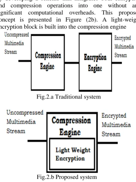
YSTEMVideo compression and data encryption are both computationally expensive tasks. The scheme presented in Figure (2a) restricts a custom hardware design for the DWT that requires low power consumption and hardware usage. Such a design also limits an efficient delivery of scalable video streams. These restrictions can be alleviated by developing a scheme that integrates both encryption and compression operations into one without any significant computational overheads. This proposed concept is presented in Figure (2b). A light-weight encryption block is built into the compression engine
Fig.2.a Traditional system
Fig.2.b Proposed system
III. I
MAGEC
OMPRESSIONU
SINGD
ISCRETEW
AVELETT
RANSFORMThe wavelet transform (WT) has gained widespread acceptance in signal processing and image Compression. Because of their inherent multi-resolution nature, wavelet-coding schemes are especially suitable for applications where scalability and tolerable degradation are important. Recently the JPEG committee has released its new image coding standard, JPEG-2000, which has been based upon DWT.
A. Sub-Band Coding
Copyright © 2013 IJECCE, All right reserved
in speech coding and later in image coding because of its inherent advantages namely variable bit assignment among the sub-bands as well as coding error confinement within the sub-bands.
Where
Downsample coumns : keep the even endexed columns
Downsample rows : keep the even endexed rows
Convolve with filter X the rows of entry
Convolve with filter X the columns of entry
Fig.3. Separable 4-subband Filter bank
Fig.4.Partition of the Frequency Domain
Woods and O'Neil are used a separable combination of one-dimensional Quadrature Mirror Filter banks (QMF) to perform a 4-band decomposition by the row-column approach as show in Fig.3. Corresponding division of the frequency spectrum is shown in Fig.4. The process can be iterated to obtain higher band decomposition filter trees. At the decoder, the sub-band signals are decoded, upsampled and passed through a bank of synthesis filters and properly summed up to yield the reconstructed image.
B. From sub-band to wavelet coding
Over the years, there have been many efforts leading to improved and efficient design of filter banks and sub-band coding techniques. Since 1990, methods very similar and closely related to sub-band coding have been proposed by various researchers under the name of Wavelet Coding (WC) using filters specifically designed for this purpose. Such filters must meet additional and often conflicting requirements. These include short impulse response of the analysis filters to preserve the localization of image features as well as to have fast computation, short impulse response of the synthesis filters to prevent spreading of artifacts (ringing around edges) resulting from quantization errors, and linear phase of both types of filters since nonlinear phase introduce unpleasant waveform distortions around edges. Orthogonality is another useful requirement since orthogonal filters, in
addition to preservation of energy, implement a unitary transform between the input and the sub-bands. But, as in the case of 1-D, in two-band Finite Impulse Response (FIR) systems linear phase and orthogonality are mutually exclusive, and so orthogonality is sacrificed to achieve linear phase.
IV. L
IGHTWEIGHTM
ULTIMEDIAE
NCRYPTIONS
CHEMEA. Multimedia security using the dwt
In this section, we give a brief summary of the security perspective of parameterized DWT filter. The overall scheme for multimedia authentication and encryption as well.
B. Building the key space
The number of DWT operations N in an image of size M x M pixels is bounded by the limit N
loge(M).For example, we can obtain up to nine levels of wavelet decomposition for an image of size 512 x512 pixels. One level of wavelet decomposition involves two filtering operations: one each along the row and column directions. Thus, we can choose up to 18 different a value, one each for the 18 different instances of DWT kernels being used in the operation. The test image Lena was used for this simulation. The variations of a beyond the range of 1 to 3 yields a poor PSNR value, indicating poor compression of the coefficients. Thus, the parameter a can be varied between numerical range of 1 to 3 while yielding satisfactory compression. We can use 8 bits to divide the interval from 1 to 3 into subintervals of 0.008. Hence, it will take 8 bits to represent one a parameter. This gives us a keys pace of 144 bits for a 9 level decomposition.C. Multimedia Security
The main advantage of the lightweight encryption scheme is that, while maintaining competitive compression performance and providing security, it comes at extremely low computational overhead. Use a wavelet filter parameterization scheme to provide key dependency to a blind watermarking algorithm. Similarly, the 144-bit keys pace can be used to encrypt input frames. This level of security can suffice for the soft encryption requirements of mobile multimedia applications and surveillance applications as previously mentioned.
Copyright © 2013 IJECCE, All right reserved exceptionally well at low bitrates and is thus well suited
for mobile applications. In a mobile environment typically at least on one side there is low computing power. If visual content is to be transferred securely from one mobile device (like a mobile phone or a PDA) to another such device, computing power is restricted on the encoding and the decoding side, which could rule out full encryption as a feasible option for providing confidentiality. Furthermore, in such settings, there is often no need for complete protection of the visual content (cf. the notion of “hard” vs. “soft” encryption). In some application scenarios a degradation of quality (in terms of resolution or quality) for wrong keys is sufficient, as long as the full quality visual data can only be accessed with the unique correct key. In commercial scenarios access to a degraded version of the visual content often is a desired effect as an incentive for buying the full quality version (“transparent encryption”). Another consideration is that with full bits stream encryption, standard bit stream compliance is lost. A method for lightweight encryption that produces standard compliant bits streams is preferable. We can phrase requirements for lightweight encryption in the presented setting:
• low demands on computational power
• retain compression performance comparable to the standard CDF 9/7 biorthogonal wavelet filter in JPEG2000
• provide sufficient security with respect to target application
• support transparent encryption
• retain standard JPEG 2000 bit stream compliance
V. DWT A
RCHITECTURE ANDD
ESIGNFigure.5 provides an overview of our parameterized DWT architecture. The input data (one pixel input per cycle) x is pipelined for eight cycles. In this block, we perform shift and add operations to implement fractional multiplications for the DWT filter. The high and low pass filter coefficients are the final outputs of the DWT filter.
Fig.5 DWT architecture
We performed several optimization steps to reduce the cost of the underlying hardware, as summarized below: 1) Division by binary coefficients (e.g. 1/64, 1/16, 1/4) was performed using arithmetic shift operations. This eliminates the requirement for multipliers in the circuit and reduces the number of multipliers from 69 to 23. 2) Eight out of the nine inputs are passed through four adders to reduce the number of variables to five. These values (labeled as w0, w1, w2, w3 and w4) are multiplied with a, a2 and a−1 to get the necessary intermediate values which are input to shift and add logic. This optimization gives a tremendous savings in hardware. It reduces the number of adders in the design from 70 to 41 and the number of multipliers from 23 to 13.
3) The input stream was pipelined. As shown in Figure 5, our architecture takes one pixel (or channel input) as the input and outputs the low and high pass signal coefficients with a finite latency. Increasing the system latency allows us to achieve a higher clock speed (and hence higher throughput). A direct implementation of this architecture using a Virtex-XC4VLX40 FPGA resulted in a clock frequency of 60 MHz which was improved by pipelining the critical path.
A. Reconfigurable Constant Multiplier
The parameterized low and high pass filters were implemented using architecture given in Figure 5 using several multiplier units. The wi, i 2 {0, 1, 2, 3, 4} values are obtained by summing the inputs for symmetric taps in the DWT implementation as shown in Figure 5. wi is calculated as follows (where x(i-j) is the input x pipelined by j cycles):
Wi(k) = x(k+i)+x(k-i), I belong to {0,1,2,3,4} Then, we can represent the filter expressions as:
Here Ki(α) and K^i(α) are the functions of the variable and wi, are obtained from the pipelined input. The values of functions Ki(α) and K^i(α) remain the same as long as we have the same _ parameter. This implies that the values of these functions behave as constants and change only when we change the encryption key (and the associated parameter). This value can thus be computed and hard-coded into the circuit. This constant multiplication can easily be mapped to a reconfigurable hardware with programmable LUTs. If the input is represented by B1 bits and constant is represented by B2 bits, we can use (B1 + B2) B2-input LUTs to get the output values of H1(k) and H2(k). Alternatively we can break down a (B1 ×B2) bit multiplication into smaller input LUTs.
Copyright © 2013 IJECCE, All right reserved Fig.6. LUT architecture
Fig.7. Illustration of 12-bit constant multiplication with a 8-bit input.
(a) The individual bits of product are obtained as output of a 8-LUT.
(b) 4-LUTs are used in the implementation with the input A divided into two 4-bit values
1) 4 × 4 Bits Multiplier using LUTs: Arbitrary hardware multipliers can be implemented using Propagate and Generate algorithm. We make some interesting observations to build a direct LUT-based multiplier.
Let A and B be the two operands, both being 4 bits long. We define Pi= Ai_ Biand Gi, = AiBi. The output bit and the sum at each stage can be represented as
Si = Pi ^ CiCi+1= Gi + PiCi On simplification, we get
C1= G0= A0B0
C2= G1+ P1C1= A1B1+ (A1^B1)A0B0… S1= A1^B1^C1= A1^B1^A0B0
S2= A2^B2^C2= A2^B2^(A1B1+A1^B1)A0B0)… We can observe that Si is a function of inputs and is characterized uniquely by a logical expression. If one of the inputs (say B) is a constant, Si can be represented as a logic function of bit values of A.
Si= fi (A3, A2, A1, A0) The truth table of these functions wi(...) can be evaluated either by logical simplification or by exhaustive search over the input values. Thus, we can implement a 4×4 bit constant multiplication using 8 4-input LUTs or more generically, we can implement a M × K bit constant multiplication using (M + K) K-input LUTs.
It has been discovered that the LUT size of 4 to 6 provides the best area-delay product for an FPGA. Most commercial reconfigurable devices such as FPGAs have 4-input LUTs. We therefore discuss the mapping of an M × K bit constant multiplier into 4-LUTs in the next subsection.
2) Mapping a generic RCM into LUTs: The multiplication of two inputs A and B (M-bit variable input A, K-bit reconfigurable constant B) can be mapped to LUTs similar to 4 × 4 bits multiplier by obtaining a generic expression for S1, S2 . . . SM+K−1. Si values can be represented as f(AM−1,AM−2, . . .A1) and can be therefore mapped into an M-input LUT. We have (M +K−1) Si values, requiring (M + K− 1) M-input LUTs to multiply A and B.
A (K+1)-input LUT can be built from 2 K-input LUTs (as shown in the Figure 3.2). For example, we can build a 8-LUT from 2 7-LUTs which can be synthesized from 2 × 2 = 4 6- LUTs. Thus, one 8-LUT can be made from 24 = 16 4-LUTs and an arbitrary M-LUT from 2M−4 4-LUTs.
Figure.7 gives an example of multiplication of 8-bit number with 12-bit constant (M = 8, K = 12). Figure 7(a) depicts implementation using 8-LUTs. 20 8-LUTs or equivalently 128 4-LUTs are used in the design. Figure 7(b) provides an alternative implementation of the same multiplication by breaking the input number into multiples of 4-bit values. 4-input LUTs are used to obtain the X and Y values which are then added together using an adder. This implementation requires 32 4-LUTs and a 20 bit adder. This design requires less LUTs but the presence of 20-bit adder may slow down the clock speed of such a design.
VI. R
ESULTS ANDC
ONCLUSIONThe proposed multimedia encryption scheme gives promising results for image and video encryption while the underlying hardware architecture is developed using LUTs allowing reconfiguration and providing high throughput. The key information is embedded into the configuration bit stream of reconfigurable hardware. To the best of our knowledge, this is the first such scheme, optimized to provide high throughput multimedia delivery alongside with multimedia encryption using parameterization of compression blocks.
The resultant waveform for the proposed architecture which is taken from Modelsim 6.3c simulator software is show in fig.8.
Copyright © 2013 IJECCE, All right reserved
F
UTUREW
ORKThis project can also be extended to use the “Multiplier Design Based on Ancient Indian Vedic Mathematics” instead of the normal Multiplier used in present DWT architecture to obtain better performance.
R
EFERENCES[1] A. Pande and J. Zambreno “A reconfigurable Architecture for secure multimedia delivery” in IEEE Transactions in 23rd
international conference on VLSI design 2010.
[2] A. Pande and J. Zambreno “An efficient hardware architecture for multimedia encryption and authentication using DWT” in IEEE CS Intlsysvlsi 2009.
[3] A. Pande and J. Zambreno, “Design and analysis of efficient reconfigurable wavelet filters,” in Proceedings of the IEEE Intl.
Conf. on Electro Information Technology, 2008, pp. 337–342. [4] A.Pande and J. Zambreno, “Polymorphic wavelet architecuture
over reconfigurable hardware,” in IEEE Intl. Conf. on Field
Programmable Logic and Applications, 2008, pp. 471–474. [5] M. Martina and G. Masera, “Multiplierless, folded 9/7 5/3
waveletVLSI architecture,” IEEE Transactions on Circuits and
Systems II, vol. 54,no. 9, pp. 770–774, Sep. 2007.
[6] H. Schwarz, D. Marpe, and T. Wiegand, “Overview of the scalable video coding extension of the H.264/AVC standard,”
Circuits and Systems for Video Technology, IEEE Transactions on, vol. 17, no. 9, pp. 1103–1120, Sept. 2007.
[7] A. Mittal, A. Pande, and P. K. Verma, “Content-based network resource allocation for mobile engineering laboratory
applications,” in Proceedings of the Intl. Conference on Mobile Learning, 2007, pp. 146–152.
[8] A. Mittal, S. Gupta, S. Jain, and A. Jain, “Content-based adaptive compression of educational videos using phase
correlation techniques,” ACM/ Springer Multimedia Systems,
vol. 11, no. 3, pp. 249–259, 2006.
A
UTHOR’
SP
ROFILEMr. Babu. M
Working as an Asst.Professor in PSR REngasamy College of engineering, Sivakasi since July 2012. Finished M.E. from Eawari Engineering College, Chennai. Area of specialization is VLSI Design. Email: [email protected]
Mr. Mukuntharaj C
Working as an Asst.Professor in PSR Rengasamy College of engineering, Sivakasi since June 2012. Finished M.Tech. from Kalasalingam University. Area of Specialization is VLSI Design.
Email: [email protected]
Ms. Saranya. S
Working as a Software Tester in Tata Consultancy Services, Chennai since November 2011. Finished M.E. from Eawari Engineering College, Chennai. Area of Specialization is VLSI Design.