ISSN (Print) : 2320 – 3765
ISSN (Online): 2278 – 8875
I
nternational
J
ournal of
A
dvanced
R
esearch in
E
lectrical,
E
lectronics and
I
nstrumentation
E
ngineering
(A High Impact Factor, Monthly, Peer Reviewed Journal)
Website: www.ijareeie.com
Vol. 8, Issue 3, March 2019
Cold Test Rejection Analysis and Quality
Improvement
Poonguzhali.I1, Gloria Pauline Diamond2, Prithi.P3
Assistant Professor, Department of ECE, Panimalar Institute of Technology, Chennai, Tamilnadu, India1
UG Student, Department of ECE, Panimalar Institute of Technology, Chennai, Tamilnadu, India2
UG Student, Department of ECE, Panimalar Institute of Technology, Chennai, Tamilnadu, India3
ABSTRACT: On manufacturing process of Engines, the Engine assembly line consists of 32 machines that perform various activities that contribute to production of engines. Our project involves the identification of the major problem in those machines and choosing one of the best problems (cold test) and improving the pass ratio of that particular machine. After the in-depth analysis of the cold testing we infer five basic problems like the crank and cam issue, oil leak, fuel leak, vibrations and breakaway torque. Out of these problems the crank and cam issue was chosen and various techniques were performed to reduce the rejection count in order to reduce the rejection in the overall cold testing. Each problem is entitled around the production line of the engines, and involves out of the box solution for complex problem. Solving these problems would eventually improve the quality of the manufacturing process by 80%.
KEYWORDS: Cold test, Crank and Cam, GEMS, Crimping, Rejection analysis, Pass ratio
I. INTRODUCTION
The quality of a machine is improved by performing some improvement activities. The rejections in the machines are analysed and the various causes, its impact on the society is also taken into consideration and then the idea to control the rejections in the machines is proposed. The rejections were maximum in the cold testing machines. The “cold test” is the end of line test and it is mainly used to check the quality of the machines. Productivity and quality are two important aspects have become great concerns in today’s competitive global market. Every production/manufacturing unit mainly focuses on these areas in relation to the process as well as product developed [5]. There is a trend in the automotive industry towards eliminating mechanical and hydraulic control systems and replacing them with electronic controls. The rise of electric vehicles (EV) is beginning to look like slowly developing tsunami [12].The overall objective of the project is to improve the Pass Ratio of the assembly of machine. Each individual machine undergoes different testing routines and mechanism to check its operational feasibility and maintenance status at the assembly line. The testing process reports the point of failure and position of failure in the machines during different manufacturing phases. We primarily focus on the problem which causes failure of the machine and analyse the process which machine and analyse the process which causes the problem. It’s causes and effects are gauged with the illustration of the PARETO CHART, which effectively streamline the problem solving. The Pass Ratio of all the machine in the Assembly line are monitored for months and reported for analysis over the period of time
II. METHODOLOGY
ISSN (Print) : 2320 – 3765
ISSN (Online): 2278 – 8875
I
nternational
J
ournal of
A
dvanced
R
esearch in
E
lectrical,
E
lectronics and
I
nstrumentation
E
ngineering
(A High Impact Factor, Monthly, Peer Reviewed Journal)
Website: www.ijareeie.com
Vol. 8, Issue 3, March 2019
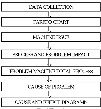
Fig. 1 Flow chart
III. DATA COLLECTION
MACHINE SEPT O C T NO V D EC
ST1 -CO LD TE ST 262 96 956 778
ST2-CO TTER CHECK 99 1 25 883 723
ST1 -CO LD TE ST 1 78 68 536 439
ST-1 3 TIMING CHAIN V IS IO N CHE CK 96 60 41 2 1 95
ST-1 1 FINAL VISIO N CHECK 29 1 8 201 1 57
ST-1 4 CO NRO D LO O SE N N/R 1 0 1 7 293 1 55
ST-55 O IL PAN SE AL G AND V IS IO N CHE CK 1 6 1 9 47 1 47
ST-3 V ALV E SPRIN G VISIO N CHE CK 20 9 1 36 1 40
ST-6 PIS TO N CO NRO D VISIO N BACKUP 35 53 301 1 00
ST6-IPT#2 TES T 38 1 1 1 80 88
ST-20 MANUAL M LA AND HLA RECHE CK 46 22 1 35 88
ST-9 F/W HEE L AND D/PULLE Y CHE CK 0 6 1 97 83
ST-21 CAM CAP AND S W ING ARM VISIO N CHECK 1 33 1 36 704 76
ST-1 B/PLATE S EAL G AND V IS IO N CHECK 46 0 1 81 65
ST -1 1 END PLAY TES T 39 25 1 1 4 51
ST-1 2 TO UCH PRO V E CHECK 8 1 67 49
ST 1 2-1 -M LA RECHE CK 58 0 277 45
ST-1 2 O IL S EAL PRES S 0 0 44 41
Table 1 Rejection Analysis
Table 1 refers to the number of rejections in each machine for various months. From this we find the machine with the highest amount of rejections and then we correct it.
IV.ENGINE QUALITY CONTROL
The objectives of the engine quality control are as follows:
To ensure best quality engine. To reduce part rejection.
To achieve a salvage PPM of 80 in plant 1 To achieve 10 PPM local part quality.
To achieveCS-10000
DATA COLLECTION
PARETO CHART
MACHINE ISSUE
PROCESS AND PROBBLEM IMPACT
PROBLEM MACHINE TOTALPROCESS
CAUSE OF PROBLEM
ISSN (Print) : 2320 – 3765
ISSN (Online): 2278 – 8875
I
nternational
J
ournal of
A
dvanced
R
esearch in
E
lectrical,
E
lectronics and
I
nstrumentation
E
ngineering
(A High Impact Factor, Monthly, Peer Reviewed Journal)
Website: www.ijareeie.com
Vol. 8, Issue 3, March 2019
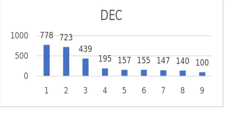
778 723 439
195 157 155 147 140 100 0
500 1000
1 2 3 4 5 6 7 8 9
DEC
V. PROBLEM IDENTIFICATION
The fig.2 shows the maximum amount of rejection happens during the cold test check. By using the Pareto analysis the following listed operation contribute 80% of process rejection. The background of the problem is analysed and the improvement is done.
Fig. 2 Pareto Graph
VI. COLD TEST SYSTEM CHECK
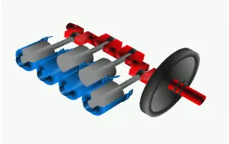
Fig. 3 Cold Test Machine
The cold test monitoring i.e. the final test after the assemble line and before shipping the engine to the customers, consists the final control of engine in order to access its state of health [1]. Cold Test System finds issues introduced during the final engine assembly stages and includes high-speed tests, low speed tests and static tests with operator inspection. It detects low vacuum, bad oil pump, EGR valve functionality, incorrect engine timing, leaking fuel rail, damaged fuel injectors, knock sensors, missing/damaged gaskets. Examples of the main tests:
1. Oil system - To test the oil system, the crankshaft is rotated by an electric motor at a fixed speed.
2. Fuel system- To test the system test will identify missing or damaged gaskets and oil pumps not meeting specifications of the fuel system, the engine is rotated
3. Vibrations-To test for unwanted vibration in the engine, the crankshaft is rotated by the electric motor at a fixed speed.
4. Crank and cam-The crank and cam are used for finding the engine’s exact timing. The crank and cam are used in both kappa engine and the U-engine
ISSN (Print) : 2320 – 3765
ISSN (Online): 2278 – 8875
I
nternational
J
ournal of
A
dvanced
R
esearch in
E
lectrical,
E
lectronics and
I
nstrumentation
E
ngineering
(A High Impact Factor, Monthly, Peer Reviewed Journal)
Website: www.ijareeie.com
Vol. 8, Issue 3, March 2019
COLD TESTING ISSUES:
The different components which are checked by Cold Test are: - Oil Pump, Oil Pressure Regulating \ Relief valve, Intake Valves, Exhaust valves, Camshaft, Valve Drive, Crankshaft & Balancer Shaft (for excess vibration), Main Bearings, Connecting rod Bearings, Pistons, Piston Rings, Head Gasket, Ignition System, Spark Plugs and Spark duration, Injector Valves, RPM Sensor & RPM Sensor wheel, Coolant etc[2].
Table 2 Basic Issues of Cold Test
The designer could develop software based 3D models and it could be tested many number of times at different working conditions. The ANSYS software is used for this purpose [3].
`
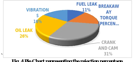
Fig. 4 Pie Chart representing the rejection percentage
From the pie chart as shown in the Fig. 4 when compared to all the problems, THE CRANK AND CAM ISSUE has the most rejection percentage. By decreasing the rejections in the crank and cam we will be able to decrease the total number of rejections in the quality line.
VII. CRANK AND CAM SHAFT CAM SHAFT:
The cam shaft and its associated parts control the opening and closing of the two valves [8]. The camshaft is a mechanical component of an internal combustion engine. It opens and closes the inlet and exhaust valves of the engine at the right time, with the exact stroke and in a precisely defined sequence. Camshaft is used in the engine for transfers’
FUEL LEAK
11% BREAKAWAY
TORQUE [PERCEN…
CRANK AND CAM
31% OIL LEAK
26%
VIBRATION S 16%
PROBLEMS TOTAL
COUNT OF FUELLEAK 46
COUNT OF BREAKAWAY TORQUE 65
COUNT OF CRANKAND CAM 125
COUNT OF OIL RELIEF 104
ISSN (Print) : 2320 – 3765
ISSN (Online): 2278 – 8875
I
nternational
J
ournal of
A
dvanced
R
esearch in
E
lectrical,
E
lectronics and
I
nstrumentation
E
ngineering
(A High Impact Factor, Monthly, Peer Reviewed Journal)
Website: www.ijareeie.com
Vol. 8, Issue 3, March 2019
Fig. 5 Camshaft
motion to inlet & exhaust valve [9]. The camshaft is driven by the crankshaft by way of gearwheels, a toothed belt or a timing chain. With a transmission ratio of 2:1, the rate of rotation of the camshaft is half that of the crankshaft. The camshaft is driven by the crankshaft through timing gears cams are made as integral parts of the camshaft and are designed in such a way to open and close the valves at the correct timing and to keep them open for the necessary duration.[10]The camshaft structure is shown in the fig.5 .
CRANKSHAFT:
Crankshaft is large volume production component with a complex geometry in the Internal Combustion (I.C) Engine[6]Crankshaft is a large component with a complex geometry in an engine which converts the reciprocation displacement of a piston to a rotary motion with four link mechanism [4] . Crankshaft experiences large forces from gas combustion. This force is applied to the top of the piston and since the connecting rod connects the piston to the crank shaft, the force will be transmitted to the crankshaft[7]A crankshaft—related to crank—is a mechanical part able to perform a conversion between reciprocating motion and rotational motion. In a reciprocating engine, it translates reciprocating motion of the piston into rotational motion; whereas in a reciprocating compressor, it converts the rotational motion into reciprocating motion. The crankshaft and its structure are shown in fig.6.
Fig. 6 Crankshaft
CRANK AND CAM ISSUES:
The crank and cam are used for finding the engine’s exact timing. The crank and cam are used in both kappa engine and the U-engine. During the cold testing of a machine there occurs different issue at different RPM
AREA OF THE PROBLEM (BLOCK DIAGRAM)
ISSN (Print) : 2320 – 3765
ISSN (Online): 2278 – 8875
I
nternational
J
ournal of
A
dvanced
R
esearch in
E
lectrical,
E
lectronics and
I
nstrumentation
E
ngineering
(A High Impact Factor, Monthly, Peer Reviewed Journal)
Website: www.ijareeie.com
Vol. 8, Issue 3, March 2019
that consists of the male type ODU the necessary power for the engine to be tested is provided. The pin number 26, 27,28 of the ODU gets activated when the flywheel rotates at 500 rpm, these pins activate the input line of the crank and cam. When the input line is connected more crank and cam NG occurs due to the following problems
1. Wiring harness cable frequent damage and wire cut issues
2. Wire directly routed to ODU unit resulting the ODU terminal to frequently come out while machine masking
3. Rough handling of the wires
4. Wear and tear of the cable is only 2 months
5. Wire gets damaged due to handling
6. Lock clip may get damaged during the assembly process
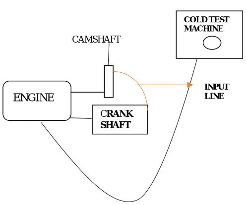
Fig.7 Block diagram
BEFORE:
Fig. 8 Before Improvement
COLD TEST MACHINE
CRANK SHAFT
ENGINE
CAMSHAFT
ISSN (Print) : 2320 – 3765
ISSN (Online): 2278 – 8875
I
nternational
J
ournal of
A
dvanced
R
esearch in
E
lectrical,
E
lectronics and
I
nstrumentation
E
ngineering
(A High Impact Factor, Monthly, Peer Reviewed Journal)
Website: www.ijareeie.com
Vol. 8, Issue 3, March 2019
PROPOSED IDEA AND IMPROVEMENT:
AFTER:
1. Cable is changed from single core to 3 wire 2. Crimping of the wire
3. Additional connector with match plate is provided 4. Crank and cam NGs are reduced
Fig. 9 After Improvement
VIII. RESULT AND DISCUSSION
The bar graph shows the variation in the number of rejections before and after the implementation. The number of rejections in the crank and cam is reduced from 125 machines to 20 machines and hence the total NG count for the cold test bud is reduced from 778 to 278. Therefore, we are able to improve the quality and reduce the rejection of an engine
Fig.10 Bar graph of the improvised results
IX. CONCLUSION
The cold test monitoring, i.e. the final test after the assembly line and before shipping the engine to the customer, consists in the final control of engine in order to assess its state of health the cam after the implementation of modification. We can observe the variation of rejection in the graph before and after implementation. By minimizing
46 65
125
104
65
40 63
20
100
55
0 50 100 150
COUNT OF FUEL LEAK
COUNT OF BREAKAWAY
TORQUE
COUNT OF CRANK AND
CAM
COUNT OF OIL LEAK
COUNT OF VIBRATIONS
COLD TEST ISSUES
ISSN (Print) : 2320 – 3765
ISSN (Online): 2278 – 8875
I
nternational
J
ournal of
A
dvanced
R
esearch in
E
lectrical,
E
lectronics and
I
nstrumentation
E
ngineering
(A High Impact Factor, Monthly, Peer Reviewed Journal)
Website: www.ijareeie.com
Vol. 8, Issue 3, March 2019
rejections, the quality of the engine will increase thus saving a lot of time. Hence the primary objective of this project is fulfilled by carrying out all these changes mentioned below:
1. Increasing the process efficiency 2. Improved quality
3. Reduction in the rejection 4. Reduction in the wastage of scrap 5. Stability in the manufacturing
REFERENCES
[1] S.Delvecchio, G.Dalpiaz, O.Niculita, A. Rivola, Condition monitoring in diesel engines for cold test application. PART I: vibration analysis for pass/fail decision
[2] Ankit Khurana, Pervading Cold Testing of Engines in the Automobile Zone, Vols.110-116,pp. 4544-4548
[3] S. Sivabalan, .Satishkumar .G, R. Siridhar, S. Joseph Irudhaya Raja -Analysis of cam and cranks shaft gear material for single cylinder petrol engine
[4] Farzin. H ,Montazeradgh and Ali Fateni- stress analysis and of crankshaft subject to dynamic loading
[5] Dhanshree Hirulkar, Madhavi Andhare, Priyanka Pethe, Tanushree Khorgade & Santosh Sakore., Paper on wire cutting machine for wire harnessing imdustry ,March 2017
[6]M. Srihari, Shaik Himam Saheb & S. Vijaya Nirmala Assistant Professor, Guru Nanak Institute of Technology, Hyderabad, Telangana Design And Analysis Of Crankshaft For 4- Stroke Deisel Engine-2016
[7]K. Thriveni,Dr.B.JayaChandraiah- Modeling and Analysis of the Crankshaft Using Ansys Software- International Journal of Computational Engineering Research,Vol, 03,Issue, 5
[8]Vulleru Swamulu, N.Siva Nagaraju , Teege Srinivas- Design And Analysis Of Cam Shaft For Multi Cylinder Engine -International Research Journal Of Engineering And Technology (IRJET) E-ISSN: 2395-0056 Volume: 02 Issue: 06 Sep-2015
[9] M.Roshan Kumar Patro, Dr.Prabhu Prasad Mishra-. Design and Analysis of Cam Shaft in Automobiles Using FEM, JULY 2017
[10]Dr. CH. S. Naga Prasad- Design and Manufacturing of a Camshaft Used in Multi Cylinder Engine -ISSN 2348–2370 Vol.09,Issue.05, April- 2017, Pages:0651-0654.