ISSN (Print) : 2320 – 3765 ISSN (Online): 2278 – 8875
I
nternational
J
ournal of
A
dvanced
R
esearch in
E
lectrical,
E
lectronics and
I
nstrumentation
E
ngineering
(An ISO 3297: 2007 Certified Organization)
Vol. 5, Issue 6, June 2016
Position Control of Servo Motor Using Fuzzy
Logic Controller
Nirmala Ashok Dange1, Ashwini Pawar2
Student, Department of Electrical Engineering, G.H.Raisoni Institute of Engineering and Technology, Pune,
Savitribai Phule Pune University, Pune, India1
Prof., Department of Electrical Engineering, G.H.Raisoni Institute of Engineering and Technology, Pune,
Savitribai Phule Pune University, Pune, India2
ABSTRACT: By far most of the present day methods use the normal PID controllers due to their clear and fiery diagram, sensible expense, and feasibility for direct systems, however routine PID controllers are by and large not effective if the techniques included are higher demand and time delay structures. For this, Fuzzy Logic controllers were appeared. In case we solidify the two clever control structures, the issue will be resolved. The utilization of FLC's to servo systems produces comes about superior to anything conventional controllers. It is seen that, if there is a conformity in system parameters or weight unsettling impacts, the response of structure due to relating vital backup (PID) controller is essentially affected and PID controller needs retuning . Nevertheless, FLCs secure the needed response over broad assortment of system parameters and weight unsettling impacts. A FLC as a rule gives best results over those of customary controllers, to the extent the response time, settling time and particularly in quality. The objective of this paper is to dissect the time determination execution between routine controller and Fuzzy reason controller in position control course of action of a DC servomotor. This will fuse design and change of a controller for position control using Matlab/Simulink. The degree of this work is to apply two sorts of controller specifically PID and Fuzzy reason controller. The item part fuses programming continuous programming using Matlab/Simulink. Finally, the item will consolidate with hardware for position control of servo structure.
KEYWORDS:PID, fuzzy logic, position control system, servomotor.
I. INTRODUCTION
ISSN (Print) : 2320 – 3765 ISSN (Online): 2278 – 8875
I
nternational
J
ournal of
A
dvanced
R
esearch in
E
lectrical,
E
lectronics and
I
nstrumentation
E
ngineering
(An ISO 3297: 2007 Certified Organization)
Vol. 5, Issue 6, June 2016
plant director [7], [8]. A FLC for the most part gives best results over those of conventional controllers, in regards to the response time, settling time and particularly in healthiness. The quality of FLC is admirable part in motor drive applications, where, the structure parameters are comprehensively changing in the midst of plant operation. Due to non-straight structure of the FLC, the essential framework issue lies in the determination of the consistent and completion rule set and the condition of enlistment limits. In any case, FLC's framework is made less requesting by warm and significance mechanical assemblies of the Fuzzy method of reasoning. In this paper, the possibility of Fuzzy justification has been used for position control, using dc servomotor. Consequent to the presentation of Fuzzy set theory by Zadeh and the essential advancement of a Fuzzy controller by Mamadani, Fuzzy control has gotten a wide affirmation, as a result of the closeness of deriving basis to human thinking and has found applications in various power plants and power systems. It gives an intense technique for changing over the expert sort control data into a modified control philosophy. Two reasons routinely set apart to seek after Fuzzy control are the aching to meld semantic control rules and the need to diagram a controller without adding to a definite system model. The principle Advantages of the Fuzzy control frameworks are as per the following.
II. IDESIGN OF CONTROLLER
In procedure control today, more than 95% of the control circles are of PID sort, most circles are really PI control. PID controllers are today found in all regions where control is utilized. The controllers come in a wide range of structures. There are standalone Systems in boxes for one or a couple circles, which are fabricated by the hundred thousand yearly. Fig. 1 demonstrates the piece chart of PID controller.
ISSN (Print) : 2320 – 3765 ISSN (Online): 2278 – 8875
I
nternational
J
ournal of
A
dvanced
R
esearch in
E
lectrical,
E
lectronics and
I
nstrumentation
E
ngineering
(An ISO 3297: 2007 Certified Organization)
Vol. 5, Issue 6, June 2016
1. Ziegler-Nichols Method
Ziegler and Nichols had proposed a famous tuning parameter of PID controller in 1942. Steps involved in this method are as follows:
1. First, note whether the required proportional control gain is positive or negative. To do so increase the step the input under manual control and see that the resulting steady state value of the process output has also increased. If so, then the steady-state process gain is positive and the required Proportional control gain, KP, has to be positive as well.
2. Turn the controller to P-only mode, i.e. turn both the Integral and Derivative modes off.
3. Turn the controller gain, KP, up slowly (more positive if KP was decided to be so in step 1, otherwise more negative if KP was found to be negative in step (1) and observe the output response. When a value of KP results in a sustained periodic oscillation in the output, mark this critical value of KP as Ku, the ultimate gain. Also, measure the period of oscillation, Pu referred to as the ultimate period. Using the
Figure 2: Response of Ultimate Gain
With some real processes the response to a step change or set point disturbance differs depending on the direction or size of the change. In this case it is irrelevant to look at the open-loop response to tune the controller. Instead the closed-loop response i.e. the behavior of the system with control has to be studied. The values of KP, KI and KD are calculated from table 1.
III. DESIGN OF FUZZY LOGIC CONTROLLER
ISSN (Print) : 2320 – 3765 ISSN (Online): 2278 – 8875
I
nternational
J
ournal of
A
dvanced
R
esearch in
E
lectrical,
E
lectronics and
I
nstrumentation
E
ngineering
(An ISO 3297: 2007 Certified Organization)
Vol. 5, Issue 6, June 2016
Figure 3: Block Diagram of Fuzzy Inference System
Crisp input information from the sensor is converted into fuzzy values for each input fuzzy set with the fuzzification block. The decision making logic determines how the fuzzy logic operations are performed and together with the knowledge base determines the outputs of each fuzzy IF-THEN rules. These two components are combined into the inference block. All the outputs are combined and converted to crispy values within the defuzzification block. Fuzzy rules can be described as a relational matrix R,R=E x EC KP x Ki x Kd
Firstly, “min” implication method is used to calculate the matrix R. Then the fuzzy reasoning results of outputsare gained by aggregation operation of fuzzy sets of inputs and matrix R, where “max-min” aggregation method isused. Because definite values of outputs are needed forapplication, the fuzzy results should be defuzzified. In this paper, the “centroid” method is used for defuzzification to gain the accurate values kp, ki and kdwhich are then sent to PID controller to control the system.
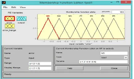
The error signal is the difference between the set point and output position of the motor. Following seven linguistic terms are used for the fuzzy sets i.e. negative big, negative medium, negative small, zero, positive small, positive medium, positive big which are denoted NB, NM, NS, ZE, PS, PM, PB respectively. The fuzzy sets are then defined by the triangular membership functions.
ISSN (Print) : 2320 – 3765 ISSN (Online): 2278 – 8875
I
nternational
J
ournal of
A
dvanced
R
esearch in
E
lectrical,
E
lectronics and
I
nstrumentation
E
ngineering
(An ISO 3297: 2007 Certified Organization)
Vol. 5, Issue 6, June 2016
Figure 4: Membership function of Changing Error
ISSN (Print) : 2320 – 3765 ISSN (Online): 2278 – 8875
I
nternational
J
ournal of
A
dvanced
R
esearch in
E
lectrical,
E
lectronics and
I
nstrumentation
E
ngineering
(An ISO 3297: 2007 Certified Organization)
Vol. 5, Issue 6, June 2016
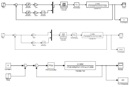
IV. PROJECT DESIGN
The idea of this project is to develop a Fuzzy Logic Controller (FLC) and conventional PID controller by using MATLAB/Simulink. The target of the project is control the position of the DC motor. The result for both simulations is elaborate and discuss in Chapter 4 and 5 in Result section.
Figure 6 Block diagram of position control of DC motor
Main controller of this project is to perform Fuzzy Logic Controller while PID controller is use to compare the performance of the controller. The FLC will provide modified control action to the existing PID control system.
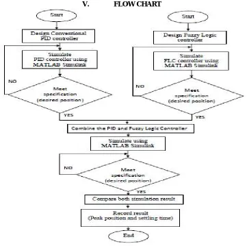
V. FLOW CHART
ISSN (Print) : 2320 – 3765 ISSN (Online): 2278 – 8875
I
nternational
J
ournal of
A
dvanced
R
esearch in
E
lectrical,
E
lectronics and
I
nstrumentation
E
ngineering
(An ISO 3297: 2007 Certified Organization)
Vol. 5, Issue 6, June 2016
VI. OVERVIEW OF SERVO SYSTEM
The review of servo system where set point is given through personal computer. The computer program (FIS) output is given to DAC which converts digital to analog signal. This analog signal is given to driver circuit of servo amplifier. From driver circuit output is given to servo amplifier which amplifies current to the motor. A potentiometer is connected to the shaft of the motor and a voltage of 5V is given to it, which is distributed over 360°. Thus the motor shaft position is converted in voltage signal and given back to PC through ADC as feedback signal.
From set point and feedback signal error is calculated the difference between the errors of two conjugative iterations gives change in error and this error and change in error is given as input to FIS which gives the output signal to achieve desired position.
TABLE 2SYSTEM PARAMETERS
Potentiometer sensitivity (Kp) 5.093 V/rad
Signal amplifier gain (Ka) 1
Back EMF constant (K) 15x10-3 V/rad/s
Armature Resistance (R) 2
Armature Inductance (Lr) 1mH
Motor Torque Constant (K ) 15x10-3 N-m/A r
Combined moment of inertia motor 42.6x10⁻⁶ Kg-m2 shaft & load referred to the
motor shaft side (Jm)
Viscous damping coefficient of the 47.3x10⁻⁶
motor referred to the motor Nm/rad/s
shaft side (Dm)
ISSN (Print) : 2320 – 3765 ISSN (Online): 2278 – 8875
I
nternational
J
ournal of
A
dvanced
R
esearch in
E
lectrical,
E
lectronics and
I
nstrumentation
E
ngineering
(An ISO 3297: 2007 Certified Organization)
Vol. 5, Issue 6, June 2016
VII. SIMULATION RESULTS
ISSN (Print) : 2320 – 3765 ISSN (Online): 2278 – 8875
I
nternational
J
ournal of
A
dvanced
R
esearch in
E
lectrical,
E
lectronics and
I
nstrumentation
E
ngineering
(An ISO 3297: 2007 Certified Organization)
Vol. 5, Issue 6, June 2016
ISSN (Print) : 2320 – 3765 ISSN (Online): 2278 – 8875
I
nternational
J
ournal of
A
dvanced
R
esearch in
E
lectrical,
E
lectronics and
I
nstrumentation
E
ngineering
(An ISO 3297: 2007 Certified Organization)
Vol. 5, Issue 6, June 2016
ISSN (Print) : 2320 – 3765 ISSN (Online): 2278 – 8875
I
nternational
J
ournal of
A
dvanced
R
esearch in
E
lectrical,
E
lectronics and
I
nstrumentation
E
ngineering
(An ISO 3297: 2007 Certified Organization)
Vol. 5, Issue 6, June 2016
ISSN (Print) : 2320 – 3765 ISSN (Online): 2278 – 8875
I
nternational
J
ournal of
A
dvanced
R
esearch in
E
lectrical,
E
lectronics and
I
nstrumentation
E
ngineering
(An ISO 3297: 2007 Certified Organization)
Vol. 5, Issue 6, June 2016
VIII. CONCLUSION
Here we Compare PID, Fuzzy PI and Fuzzy PID with respect to rise time, settling time, overshootsit is seen that the Fuzzy controller safeguards the fancied reaction, even within the sight of burden unsettling influence and changing contra1 situations. This guarantees the controller's vigor. Here we finalize the Fuzzy PID is best in terms of All parameters. The decision of guidelines and enrollment capacities has impressive impact on Fuzzy Controller execution, e.g., rise time, settling time, overshoots and so forth. It is watched that utilizing the superposition of various resulting dynamic at specific area of space, for the same mixes of forerunners, execution of FLC is enhanced impressively as far as settling time and overshoot. The blend of two arrangements of standards with same precursors however distinctive resulting diminishes the settling time and overshoot.
REFERENCES
[1] I. J. Nagrath and M.Gopal, “Control System Engineering.” Fifth Edition.
[2] Xiaodiao Huang and Liting Shi, “Simulation on a Fuzzy-PID Position Controller of the CNC Servo System”, Sixth IEEEInternational Conference on Intelligent Systems Design and Applications (ISDA’06), 2006.
[3] Dongmei Yu, QingdingGuo and Qing Hu, “Position Control of Linear Servo System Using Intelligent Feedback Controller”, Sixth IEEE International Conference on Intelligent Systems Design and Applications (ISDA’06), 2006.
[4] A. B. Patil, A.V.Salunkhe, “Temperature Controller Using Takagi-Sugeno Model Fuzzy Logic” Asian Conference on Intelligent Systems and Networks, 2006.
[5] MohdFua’adRahamat& Mariam md Ghazaly, “Performance Comparison between PID And Fuzzy Logic Controller in position Control System of DC Servomotor. Journal TeknologiMalayshia,45(D), 2006.
[6] K. S. Tang, Kim Fung Man,Guanrong Chen, and Sam Kwong, “An Optimal Fuzzy PID Controller” IEEE Transactions onIndustrial Electronics,48(4), 2001.
[7] Maki K. Habib, “Designing of Fuzzy Logic Controllers for DC Servomotor Supported by Fuzzy Logic Control Development Environment” IECON01:The 27th Annual Conference of the IEEE Industrial Electronics Society. 2001.
[8] C. C. Lee, “Fuzzy Logic in Control Systems: Fuzzy Logic Controller, Part II” IEEE Transactions on Systems, Man. andCybernetics,20(2), 2000.
[9] George K. I. Mann, Bao-Gang Hu, Raymond G. “Analysis of Direct Action Fuzzy PID Controller Structures, IEEETransactions on Systems, Man, and Cybernetics—Part B: Cybernetics,29(3), 1999.
[10] N. Thomas and D. P. Poongodi. 2009. Position Control of DC Motor Using Genetic Algorithm Based PID Controller. In: Proceedings of the World Congress on Engineering, London, U.K.
[11] M. F. A. Rahmat and M. M. Ghazaly. 2006. Performance Comparison between Pid and Fuzzy Logic Controller in Position Control System of Dc Servomotor. Journal Teknologi. 45: 1-17.
[12] P. I-Hai Lin, S. Hwang and J. Chou. 1994. Comparison on fuzzy logic and PID controls for a DC motor position controller. In Industry Applications Society Annual Meeting. Conference Record of the 1994 IEEE. 3: 1930-1935.
[13] P. A. Ahmed, Y. Mohan, A. Chauhan and P. Sharma. 2013. Comparative Study of Speed Control of D.C. Motor Using PI, IP, and Fuzzy Controller. International Journal of Advanced Research in Computer and Communication Engineering. 2: 2693-2697.
[14] S. R. Khuntia, K. B. Mohanty, S. Panda and C. Ardil. 2010. A Comparative Study of P-I, I-P, Fuzzy and Neuro-Fuzzy Controllers for Speed Control of DC Motor Drive. International Journal of Electrical and Computer Engineering. 5: 287-291.