c e-ISSN: 2348-6848, p- ISSN: 2348-795X Volume 2, Issue 11, November 2015
International Journal of Research (IJR)
Available at http://internationaljournalofresearch.org
Hybrid AC/DC Micro grid Control Using Decentralized
control for Power Management
Mr. P.D.V.S.K.Kishore *1& Mr.Mittapalli Naveen Kumar*2,
Asst.Professor, Department of Electrical and Electronics Engineering#1. M.tech Student Department of Electrical and Electronics Engineering#2.
Abstract
This paper proposes a hybrid ac/dc micro grid to reduce theprocesses of multiple dc–ac–dc or ac– dc–ac conversions in anindividual ac or dc grid. The hybrid grid consists of both ac and dcnetworks
connected together by multi-bidirectional
converters. Theproposed model is in such a way that the reliability of power can bemaintained during the whole day. This is obtained by connecting aPEM Fuel cell stack in parallel with the PV system. The proposedhybrid grid can operate in grid-tied or autonomous mode. Thecoordination control algorithms are proposed for smooth powertransfer between ac and dc links and for stable system operationunder various generation and load conditions. Uncertainty incharacteristics of wind speed, solar irradiation level, ambienttemperature, and load are also considered in system control and operation. A small hybrid grid has been modeled and simulatedusing the Simulink in the MATLAB. The simulation results show that the system can
maintain stable operation under the
proposedcoordination control schemes when the grid is switched from oneoperating condition to another.
I. INTRODUCTION
Even though three phase ac power systems have existed for over100 years due to their efficient transformation of ac power atdifferent voltage levels, keeping in mind the environmental issuessuch as global warming, pollution, depletion of fossil fuels timehad come to concentrate on renewable to concentrate on renewablesources of energy. More and more dc loads such as light-
emittingdiode (LED) lights and electric vehicles (EVs) cab be connected to ac power systems to save energy and reduce CO2 emission. When power can be fully supplied by local renewable power sources,long distance high voltage transmission is no longer necessary.A hybrid AC/DC micro grid [1] have been proposed to facilitatethe connection of renewable power sources to conventional acsystems. However, dc power from the renewable photovoltaic(PV) panels or fuel cells has to be converted into ac using dc/dc boost converter and dc/ac inverters in order to connect to an ac grid. In an ac grid, embedded ac/dc and dc/dc converters are required forvarious home and office facilities supplydifferent dc voltages .AC/DC/AC converters are commonly used as drives in order to control the speed of ac motors in industrial plants.
II. System Configuration and Modeling A. Grid Configuration
c e-ISSN: 2348-6848, p- ISSN: 2348-795X Volume 2, Issue 11, November 2015
International Journal of Research (IJR)
Available at http://internationaljournalofresearch.org
50kW Wind Turbine Generator (WTG) with Doubly Fed InductionGenerator (DFIG) is connected to an ac bus to simulate ac sources.A 65 Ah battery as energy storage is connected to dc bus througha bidirectional dc/dc converter. Variable dc load (20 kW–40 kW)and ac load (20 kW–40 kW) are connected to dc and ac busesrespectively.The rated voltages for dc and ac buses are 400V and 400V rms respectively. A three phase bidirectional dc/ac main converterwith R-L-C filter connects the dc bus to the ac bus through anisolation transformer.DUE TO increasing deployment of DGs in power systems,managing the power of different DGs and the grid hasraised a major concern [1]–[3]. In this field, microgrids havebecome a widely accepted concept for the superior connectionof DGs in power networks. Corresponding to the conventionalpower systems, ac microgrids have been established for mostand a variety of surveys have been reported particularly on thesubject of power sharing of parallel-connected sources [4]–[6].Since the majority of renewable energy sources, generate dcpower or need a dc link for grid connection and as a result of increasingmodern dc loads, dc microgrids have recently emergedfor their benefits in terms of efficiency, cost and system that caneliminate the dc-ac or ac-dc power conversion stages and theiraccompanied energy losses [7]–[10]. However, since themajorityof the power grids are presently ac type, ac microgridshare still dominant and purely dc microgrids are not expected toemerge exclusively in power grids. Therefore, dcmicrogrids areprone to be developed in ac types even though in subordinate.Consequently, linking acmicrogridswith dc micro-grids and employingthe profits of the both microgrids, has become interestingin recent studies [11]–[14]. The idea is tomerge the ac anddc microgrids through a bidirectional ac/dc converter and establishinga hybrid ac/dc microgrid in which ac or dc type energysources and loads can flexibly integrate into the microgrids andpower can smoothly flow between the two microgrids. Reference[11] proposes a hybrid ac/dc microgrid in which the renewableenergy sources and storages are
connected in a dc grid andsupplying power to the main ac grid and local ac loads. A hybriddc/ac microgrid configuration is proposed in [12], in which a dcpower line along with an energy conversion station are addedto the conventional three-phase power distribution system forthe integration of distributed domestic renewable sources. Themain idea is to use the locally generated energy and reducing thepower draw from the grid. Reference [13] proposes to combinea smart dc grid with the ac grid in order to suppress the dc busvoltage fluctuation using controllable loads and achieving thestabilization control of the ac grid using the grid-side converterinterlinking the dc and ac microgrids. A hybrid microgrid composedof various kinds of renewable energy sources is consideredin [14]. A coordinate control scheme is developed in orderto manage the whole system in different operating conditions.
Like othermicrogrids, the hybrid ac/dcmicrogrid can operateeither in grid-connected or in islanding modes and the controlsystem should be able to support the two operating modes aswell as transition between these modes. Therefore, a suitablecontrol strategy to coordinate the operation of dc sources, acsources and the IC is indispensable. This matter is more challenging the islanding operation of the hybrid microgrid wherethere is no dominant source in the grid and the load demandshould be shared among the existing sources. In such operatingcondition the IC is intended to manage the ac and dc power, thusthe control algorithm is supposed to be able to decide whetherto inject power to the dc or to the ac microgrid. In [15], a centralizedcontrol strategy is exploited for managing the powerin a hybrid ac/dc microgrid. However, the need for fast communicationlink along with the reliability concerns of this communicationsystem have propelled the microgrid managementinto the decentralized controllers among which droop control
c e-ISSN: 2348-6848, p- ISSN: 2348-795X Volume 2, Issue 11, November 2015
International Journal of Research (IJR)
Available at http://internationaljournalofresearch.org
methods have been proposed forac and dc microgrids [1], [5], [6], [16]. Despite standalone acor dc microgrids, sharing the power between ac and dc microgridcannot be achieved by the conventional droop methods.During the islanding operation, the IC at the same time takes therole of supplier to one microgrid and acts as a load to the othermicrogrid and shares the power demand between the existingsources. Another challenge is that since the generated powerin each microgrid is limited, the power management systemshould share the power demand between the existing ac and dcsources. Therefore, a specified droop method is needed to coordinatepower flows and to cover acceptable power sharing.In [16] hierarchical control method that is applied in ac powersystems for power dispatching is modified for controlling acand dc microgrids. The major focus in this study is to implementthe hierarchical control scheme for each microgrid individually.However, the operation of the interfacing convertersbetween ac and dc buses is not included. Autonomous operationof such hybrid microgrid is followed in and extendedin [19] by integrating an energy storage system to thedc microgrid. A droop control scheme is developed for controllingthe interlinking converters using a normalized bidirectionaldroop. A common per-unit range is defined and the droop characteristicsof ac and dc microgrids are mapped to common axesfor bidirectional power sharing. The strategy is to maintain theper-unit values of the voltage at dc side and the frequency at acside the same. By this control strategy the demanded load eitherin ac or dc microgrids can be shared among the whole microgridsources. However, it causes almost continuous operationof the interlinking converter for any load variations that willresult in more power loss in the converter. In order to reducethis operating losses, [20] proposes to progressively tune theenergy flow between the ac and dc parts using energy storage.This paper proposes a two-stage modified droop method forthe bidirectional power control of the IC during different operationmodes of the hybrid ac/dc microgrid. By measuring theac microgrid frequency and the dc microgrid voltage and
usingproposed droop characteristic, the power management strategyprovides the power reference for the IC. Through this controlstrategy, the two microgrids can be treated as a unified microgridin which the demanded load power can be shared betweenthe existing energy sources in this hybrid microgrid. Therefore,the installed power reserve can support the two microgrids commonlyand it allows reduced amount of reserve power for eachmicrogrid. This paper is organized as follows. In Section II, thehybrid ac/dc microgrid structure and operation modes are des-cribed.Droop control strategy for individual ac microgrids anddc microgrids is explained in Section III. Operating states of thehybrid microgrid and the proposed IC control during islandingare discussed in Section IV. Section V covers the modeling andsmall signal stability of the hybrid microgrid. In Section VI, theperformance of the proposed control strategy is demonstratedthrough time-domain simulations; and finally the conclusion isgiven in Section VII.
II. SYSTEM STRUCTURE AND OPERATION MODES
c e-ISSN: 2348-6848, p- ISSN: 2348-795X Volume 2, Issue 11, November 2015
International Journal of Research (IJR)
Available at http://internationaljournalofresearch.org
directly by the main utility grid and theIC primarily regulates the dc microgrid voltage and controlsthe power balance. In this oper-ating condition the dcsources can be made to gen-erate a constant power or can operate in maximumpower point from the renewable energy sources. In the islandingmode, and during light loading of the dc grid, the demanded power is shared among the dc sources usingtheP-Vdc droop characteristics. When over-loading happensin the dc part, the interlinking converter will also participateto share the load using the proposed ac-dc droop control.The theperfor-mance of the hybrid ac/dc microgrid isdescribed in both of these modes.
A. Grid-Connected Mode
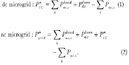
When the hybrid ac/dc microgrid is connected to the mainutility grid, DG sources in the ac microgrid are made to provide a either specified real/reactive power, or act as terminalvoltage regulator with a specified amount of active power and variable reactive power .Similarly, in dc microgrid, DG sources would be controlled to provide a specified active power. However, the utility grid isstill responsible for voltage support and power balance throughthe IC. According to Fig. 1 and neglecting the power losses, thismode can be described,
In this case the renewable energy sources in the microgridcan be operated in maximum power point, energy storages canbe charged and non-renewable sources can be managed.For Example forpeak shaving purposes, loss reduction or economical goals[4]. These power management
studieshave been studied in dc microgrids [7], [8] and it is not intendedto be followed in this paper.
B. Islanding Mode
The challenging situation among two is the islanding operation ac/dc microgrid. In this mode, the total load
demand should be shared and managed autonomo-usly by theexisting DGs in the twomicrogrids, which involves rapid andflexible active/reactive power control strategies to minimize themicrogrid dynamics. A proper load shedding strategy is also needed in case of short in locally generated power in orderto maintain the stability of the system [7]. This paper adopts decentralizedcontrol strategies based on droop control to manage thepower sharing among ac sources as well as dc sources, and betweenthe ac and dc microgrid. For judging the performance ofac/dc microgrid among different operating conditions, four are considered in the islanding mode, as follows:Islanding state I: This operation state corresponds to the islandingoperation of hybrid ac/dcmicrogrid during light load condition in both grids. The DGs ineach micro-grid will maintain its power to meet the load requirement. In thisstate, the IC halts transferring power either from onemicrogrid to other microgrid .This state is expressed by,
c e-ISSN: 2348-6848, p- ISSN: 2348-795X Volume 2, Issue 11, November 2015
International Journal of Research (IJR)
Available at http://internationaljournalofresearch.org
Islanding state III: This state is as same as state II, but the power deficit occurs in the dcmicrogrid and the ac microgridis in light load condition. Therefore, the ac sources suppliesthe needed power for dc microgrid. In this case,
Islanding state IV: This state corresponds to load demand in both microgrid are greater than the maximum available sources capacity. In this state, the IC stops transferringpower and a proper load shedding strategy must be run tostabilize the grids. This state is described by,
III. DROOP CONTROL STRATEGY FOR AC AND DC MICROGRIDS
A. Controlling DGS in the AC Microgrid
Power management using droop control is presently wellrecognized in ac microgrids. Real power generation of a DGis specified based on
frequency-droop (ω-P)characteristic[4]. The ideabehind this control is to improve the active power generation of DGs when frequency of system decreases. As same as this, for reactivepower management voltage-droop(V-P) characteristics have been exploited.ω-P and V – P
characteristics could be described mathematically by
As the reactive power is determined based on devi-ations in the bus voltage. Therefore, the DG source acts in responseto themeasured local voltage deviations caused by eitherthe system or the local load.
By this power control method, during the grid-connectedmode where the frequency of the system is fixed, real powergeneration of the DG is controlled byP°.
Fig.2. Configuration of the IC interfacing ac and dc microgrids.
c e-ISSN: 2348-6848, p- ISSN: 2348-795X Volume 2, Issue 11, November 2015
International Journal of Research (IJR)
Available at http://internationaljournalofresearch.org
B. Controlling DGs in DC Microgrid
Alternatively, to share the power among dg sources, voltage-droop (Vdc- P) control method is used.In general Vdc- P droop characteristicscan be expressed by
IV. PROPOSED IC CONTROL FOR ISLANDING OPERATION
In addition to adopting the power sharing strategies for thestandalone dc or ac microgrids, it is required to develop a propercontrol strategy for the IC to share the demanded power between these two microgrids. However, the power management for theIC control is different from standalone ac or dc microgrids control strategies. Moreover the IC is expectedto manage a bi-directional flow of power between the ac and dcMicrogrids. In addition the IC should cooperate in power sharingbetween the energy sources in both microgridswhich are having dissimilardroop characteristics. These challengingcan be handled by exploiting a proper control strategyfor the IC to transfer the required power between the microgrids. The following decentralizedcontrol strategy is adopted for this purpose.
The power management should be able to determine the amount of active power that the IC must transfer between the microgrid. In order to provide the power reference command, the dc bus voltage of the IC and the frequency of the ac microgrid are utilized as input to the power management system. By using these two
the power that has to be transferred between microgrid will be determined .and negative sign is used to represent the power transfer from dc to ac.Considering Fig. 2, the electrical energy stored in the dc capacitor is,
When switching losses in the converter are
assumed to be neglected Pdc=Pac,the dynamics in the dc capa-citor energy is the difference of power transfer betw-een ac and dc microgrids. Therefore,
On the other side, considering the w-P characteristic in the ac microgrid,
According to (22) and (23), using the forward Euler approximation with sampling period (Tc) [22] and assuming that the microgrid frequency is constant in this interval, a new droopcharacteristic for the IC called ―ac-dc droop‖ is defined as,
c e-ISSN: 2348-6848, p- ISSN: 2348-795X Volume 2, Issue 11, November 2015
International Journal of Research (IJR)
Available at http://internationaljournalofresearch.org
drop in dc and ac micro grids that the system is supposed to undergo load shedding.
Furthermore, since the IC is not the mere frequency or dcvoltage controller in the hybrid ac/dc microgrid, it is necessaryto participate in power sharing between ac and dc sources. Toimplement this scheme, the output of the ac-dc droop is fed totheVdc- Pandω-P droops of the IC.
It is necessary to mentionthat since positive sign for power transfer in the IC is consideredto be from dc to ac, the power forVdc- P droop shouldbe regarded with negative sign. Finally, according to
and the amount of power to be transferred via the IC is determinedby the two reference power calculated through these twoloops. A schematic block diagram of the proposed power managementstrategy for the IC is depicted in Fig. 4. The impact ofthe proposed droop control for the IC on the power sharing ofsources in each microgrid is illustrated within two load increasescenarios in each microgrid,
1) In the first scenario it is assumed that the dc microgridis near overloading and there is excess power in the acmicrogrid. Upon increasing the load in the dc microgrid,the dc voltage will accordingly decrease. If the voltagedrop is beyondδV, referring to the proposed ac-dc droop(Fig. 3) this voltage deviation produces a new referenceangular
frequency . This will then determinesthe reference power for the IC power controller using theconventional ω-Pdroop. This is the amount of power tobe transferred from ac to dc microgrid. Therefore, the ICtreats as a source for the dc microgrid and partly restoresthe voltage of the dc microgrid. On the other hand, the ICtakes the roll of a load for the ac microgrid and increasesthe power generation of the ac sources.
2) The other scenario happens when the ac microgrid is nearoverloading. When the ac load increases again, causes thefrequency to decrease below δώ. Referring to the proposedac-dc droop a new reference voltagev dc reference is
presented.Thisvd ref is actual dc bus voltage of the dc microgrid.Finally, by using the droop the required powerto be transferred to theVdc- P dc microgrid is determined. Therefore,according to these two scenarios whenever the loadincreases in one of the microgrids, the ―ac-dc droop‖ characteristicrelates the ac and dc microgrids using the dc linkperformance and the equivalent frequency droop characteristicof the ac micro-grid Will be determined by using the below mentioned equation.
By this power management strategy the response of IC indifferent islanding states is as follows:
Islanding state I: Throughout this state, Δω<δω andΔVdc² <δV² therefore the output of ―ac-dc droop‖ is
Fig.5. Overload blocking logic for real power controller of the IC.
Fig.6. Reactive power controller for the IC.
For dc micro grid and for ac
microgrid.Consequently, and IC transfers no power.
Islanding state II: In this state ΔVdc² < δV²
c e-ISSN: 2348-6848, p- ISSN: 2348-795X Volume 2, Issue 11, November 2015
International Journal of Research (IJR)
Available at http://internationaljournalofresearch.org
Islanding state III: In this stateΔω<δω butΔVdc² < δV² therefore, and IC supplies power to the dc microgrid.
Islanding state IV: During this state,
andΔVdc² <δV²shed. In order to block the IC for any power transfer, an overloadblocking logic shown in Fig. 5, is added at the output theproposed droop control in which by using an ―EXCLUSIVE OR(XOR)‖ logic, whenever both microgrids enter overloading theIC is blocked and no power will transfer.
The reactive power control of the IC is more straightforwardsince there is no reactive power in dc microgrid and the IC isdesignated to play as a voltage support in droop-control modeto share the reactive power with other DGs in ac microgrid.The reactive power sharing is based on the conventional droopshown in Fig. 6, the local RMS voltage is measured and usingthe droop, theV-Q
reactive power reference is determined.Since the active power transfer is the prime task of the IC, adynamic reactive power limit is added to the control block toconsider the capacity limit of the IC. The reactive limit is definedas,
Finally, a current control scheme [23] is utilized in IC controlfor tracking the reference active/reactive power calculated bythe power management system.
V. MODELING AND SMALL SIGNAL STABILITY ANALYSIS
Section IV describes the proposed droop method for the IC inthe hybrid AC/DC microgrid. This section investigates a smallsignalanalysis for the hybrid microgrid to analyze the stabilityof the system. In order to reduce system equations and for thebetter analysis of the proposed droop controller, the dc sourcesand their individual droops are aggregated to form one combineddc
source. This is also done for ac sources, dc and ac loadsas well. Therefore the hybrid microgrid shown in Fig. 1 is simplifiedfrom the perspective of IC, as shown in Fig. 7. Furthermore,as discussed in Section II, different scenarios can be consideredfor the operation of the hybrid microgrid, but for the stabilityanalysis only the worst case condition is considered whichis the islanding states II and III defined in Section II.
Fig.7. Simplified equivalent model of the hybrid microgrid.
Fig.8.Block diagram of the dc source.
A. DC Micro grid Modeling
The dc microgrid comprised of sources, loads and the dc network.Componentsmodeling are discussed in the following subsections.
1) DC Source Modeling:
c e-ISSN: 2348-6848, p- ISSN: 2348-795X Volume 2, Issue 11, November 2015
International Journal of Research (IJR)
Available at http://internationaljournalofresearch.org
controller can exactly follow the reference voltageand consequently the output voltage is equal to its referencevalue. The droop equation for the dc source is,
Linearizing (26) by using small-signal approximation leadsto,The represents the small-signal perturbation of the correspondingparameter. 2) DC Load Model:
The majority of loads in the dc microgridsutilize power electronic converters for grid connection since these converters are generally tightly regulated; theseloads behave as a constant power load (CPL) [26]. Therefore,the CPL load model is considered for stability analysis. Asshown in [26], the small signal model of CPL can be expressedby a negative resistance, as given by
3) DC Network Model:
The dc network is equivalentlymodeled as a series combination of resistance and reactance asshown in Fig. 7 The network equation can be represented asfollows,
Fig.9. Excitation system model of synchronous generator.
Fig.10. Governor and turbine model of synchronous generator.
B. Ac Micro grid Modeling
Similar to dc micro grid, the ac micro grid is also consists of acsources, ac loads and the ac network, as shown in Fig. 7. The aggregatedac source is a two-pole, three-phase synchronous machine,equipped with excitation and governor systems. Detailedsmall signal modeling of the synchronous machine is fully consideredin [27] and for the sake of brevity this is not presentedhere. A first-order excitation system is used for terminal voltagecontrol, as shown in Fig. 9. The equation of this system is,
Two first-order governor and turbine are adapted to controlthe frequency, as shown in Fig. 10.
c e-ISSN: 2348-6848, p- ISSN: 2348-795X Volume 2, Issue 11, November 2015
International Journal of Research (IJR)
Available at http://internationaljournalofresearch.org
C. IC Modeling
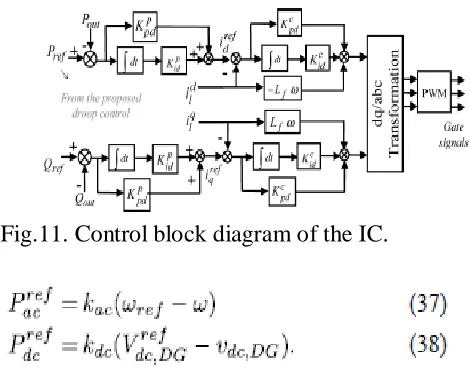
Fig. 11 shows the control block diagram of the IC in d-qreferenceframe. The real power reference is determined accordingto the proposed droop shown in Fig. 4. The active power controlloop generates the reference currenti*d using PI controller. Thecurrent control loop measures the output currents and controlsthe converter to follow the reference value using PI controller.
The droop characteristics for active power shown in Fig. 4can be expressed by,
This equation is being used to determine the reference frequency for generating required active power output for ac microgrid and voltage for generating required dc microgrod using droop cha-racteristic constant .Their the difference between reference speed and actual speed is used in determining the required voltage and reference voltage and actual voltage are used in determining the required frequency.The control block diagram is shown in Fig.11.
Fig.11. Control block diagram of the IC.
Combining (35) and (36), the reference power for the ac microgridis,
The linearized model of the proposed droop for the ac microgridcan be obtained as,
WhereVdc is the dc-bus voltage at the operating point.Similarly, the linearized reference power for the dc microgridcan be expressed by,
c e-ISSN: 2348-6848, p- ISSN: 2348-795X Volume 2, Issue 11, November 2015
International Journal of Research (IJR)
Available at http://internationaljournalofresearch.org
The parameters are defined in [28].
The linearized model of real power controller derived fromFig. 11 is [4]
Is represented by the linearized equation of the instantaneous real power in the d-q frame as,
Finally, the reference voltage for the PWM switching is followedby the current controller according to the reference current.The corresponding small-signal state space equation of thecurrent controller is,
Since the dc bus voltage in the IC is not fixed, the switchingprocess should also be considered for stability analysis.
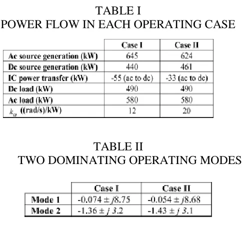
TABLE I
POWER FLOW IN EACH OPERATING CASE
TABLE II
TWO DOMINATING OPERATING MODES
Therefore, the converter and its output filter small signal model canbe represented by [29],
The small signal model of the hybrid ac/dc microgrid is developedby combining the state-space representation of eachac subsystem transferred to a global reference frame and thestate-space model of the dc microgrid.
D. Small Signal Analysis
The linearized model of the hybrid microgrid is used tostudy the small signal dynamics of the microgrid during autonomousmode of operation. Based on the system model andcorresponding parameters, the two dominating modes are:
Mode 1: Electromechanical mode of ac source which is selectedas a gas-fired turbine-generator
Mode 2: Related to the droop gain of the IC which is thefunction of .
The dominant modes are identified for two operating casesshown in Table I. The first case corresponds to the powertransfer from the ac to dc
microgrid with (thiscorresponds to the value for the proportional power sharingbetween the sources [4]) and the second relates to the powertransfer with .
c e-ISSN: 2348-6848, p- ISSN: 2348-795X Volume 2, Issue 11, November 2015
International Journal of Research (IJR)
Available at http://internationaljournalofresearch.org
amount of power participation for the ac source decreaseswhich increases the ac source damping (dominating mode).The same result can be deduced for the power transfer fromdcmicrogrid to acmicrogrid as well, in which increasing the ac-dc droop gain results inthe greater participation of dc sources in the power sharing andincreases the dominating mode damping.
Fig.12. Simulation results for Case 1.
VI. CASE STUDIES AND SIMULATION RESULTS
In order to validate the proposed power management control,a hybrid ac/dc microgrid is simulated in matlab/simulinkusing detailed switching model for the converters. Consideringthe schematic diagram of Fig. 1, the ac microgrid includes twogas-fired DG units with synchronous generators, excitation andgovernor control systems. Furthermore, the dc microgrid containstwo dispatch able dc sources. System parameters are presentedin Appendix. Different operating scenarios, configurationof loads and generation are considered in the simulations inorder to validate the performance of the proposed power managementmethod in controlling the IC in the hybrid ac/dc microgridand sharing the power between the ac and dc microgrids.
A. Case 1
In this case, the hybrid ac/dc microgrid is supposed to beconnected to the main utility grid. At first, dc sources generatea fixed power, a portion of the
demanded load is supplied bythe local sources in dc microgrid and the insufficient power isprovided through the IC. Att=1s, a large portion of the dcload switches off and the dc power generation is more than theload demand. The IC moves to the inverting mode and feedsthe surplus power to the ac grid. Similarly, at t=2sdc loadincreases and approximately matches the generated dc power.The IC power, dc load and the generated power of the dc sourcesalong with dc-bus voltage are shown in Fig. 12.
B. Case 2
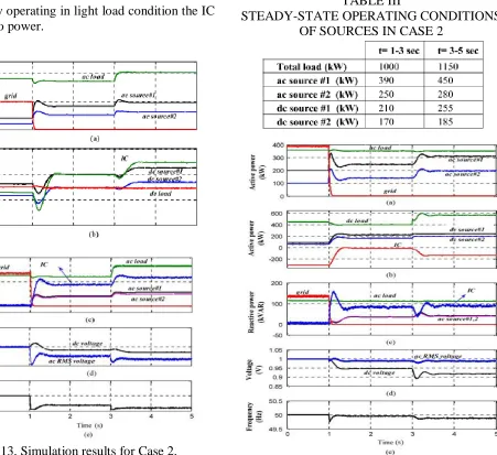
This case simulates the hybrid ac/dc microgrid operation intransition from grid-connected mode to islanding mode. Beforeislanding occurs, the dc microgrid is in light load condition andfeeds the surplus power to the ac grid. Att=1s the microgridis disconnected from the main grid, and the islandingevent is detected by the IC att=1.06s . A 60 ms delay is assumedfor typical islanding detection methods [31]. The IC controlstrategy is changed from the grid-connected to the proposedcontrol strategy for islanding control of the hybrid ac/dc microgrid.The demanded ac load is greater than the generated powerin the ac microgrid and causes the frequency drop. In order tobalance the power, the IC controller shares the surplus power inthe dc microgrid with the ac sources in the ac microgrid. Duringthe islanding operation att=2 s the ac load is increased furtherand this causes the IC to transfer more power from the dc to acmicrogrid. Simulation results are shown in Fig. 13.
C. Case 3
c e-ISSN: 2348-6848, p- ISSN: 2348-795X Volume 2, Issue 11, November 2015
International Journal of Research (IJR)
Available at http://internationaljournalofresearch.org
order to balance the power, the ICcontroller shares the surplus power in the ac microgrid with thedc sources in the dc microgrid. During the islanding operationatt=2s the dc load is increased further and this causes the ICto transfer more power from the ac to the dc microgrid. Simulationresults are shown in Fig. 14.
D. Case 4
In order to evaluate the performance of the proposed controlstrategy in different load profiles during the islanding operation,the islanded hybrid ac/dc microgrid is simulated in case 4. Thetwo microgrids
are initially operating in light load condition the IC transfers no power.
Fig.13. Simulation results for Case 2.
Att=1 s aload increase happens in the ac microgrid in which the power demandis greater than available ac generation, the IC detects the frequency drop and calculates the required power to be transferredfrom dc to ac microgrid and shares this power demandbetween sources. Then att=2 s again the load decreases and the ac microgrid enters the light load condition. After thatatt=3 s dc load is increased and the IC detects the voltagedrop and calculates the required power to be fed to dc microgrid and shares this power demanded between sources. Simulationresults are shown in Fig. 15.
TABLE III
STEADY-STATE OPERATING CONDITIONS OF SOURCES IN CASE 2
c e-ISSN: 2348-6848, p- ISSN: 2348-795X Volume 2, Issue 11, November 2015
International Journal of Research (IJR)
Available at http://internationaljournalofresearch.org
TABLE IV
STEADY-STATE OPERATING CONDITIONS OF SOURCES IN CASE 3
Summarized in Table V. It can be realized that the IC can reasonablymanage the power sharing and avoids any instabilityduring the autonomous operation of the hybrid microgrid.
Fig.15. Simulation results for Case 4.
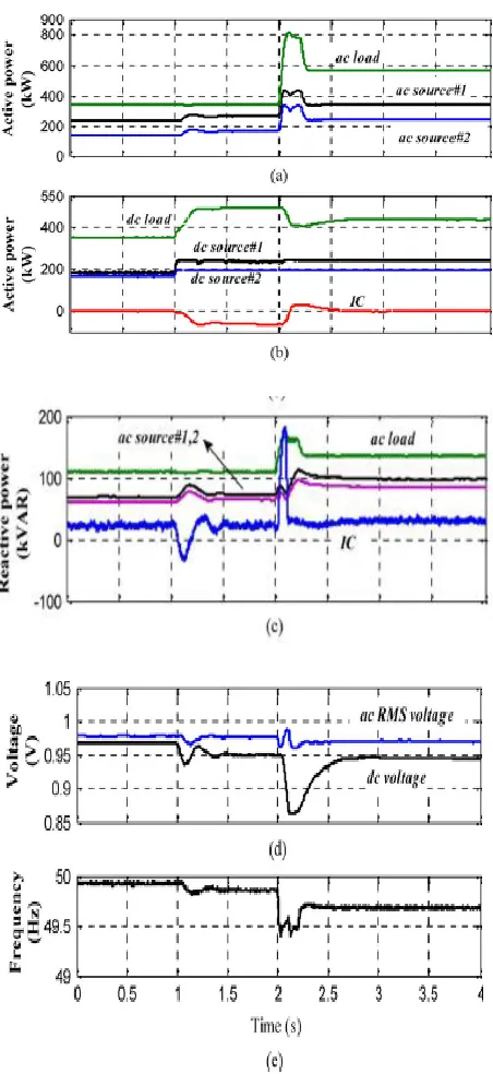
E.Case5
It simulates the performance of the IC facing over load condition on both ac and dc microgrids. Both microgrids both ac microgrid and dc micro grid are primarily operating in light load condition. Att=1 s the load power is increased from actual in the dc microgrid and causes overloading of the dc microgrid .In this condition the IC feeds the required power which is excess in ac microgrid. At
t=2 s the ac load is also increased and makes the ac microgrid overloaded. While both microgrids are over loaded, the IC transfers no power and each microgrid is responsible for the power management. Here both the grids are in overloaded condition .Due to power deficiency in bothmicro-
TABLE V
STEADY-STATE OPERATING CONDITIONS OF SOURCES IN CASE 4
Grids, dc voltage drops below allowable voltage range (0.9 p.u)and activates the dc load shedding system. On the other hand,the ac frequency also drops and a portion of ac load is shed tostabilize the ac microgrid. Fig. 16 shows the performance of thehybridmicrogrid and over load blocking logic in this study case.It is necessary to mentioned that if the overload blocking is notused, it makes the interconnection of the power managementcontrol between the ac and dc microgrids, which causes powerswing between ac and dc.
F. Case 6
c e-ISSN: 2348-6848, p- ISSN: 2348-795X Volume 2, Issue 11, November 2015
International Journal of Research (IJR)
Available at http://internationaljournalofresearch.org
Fig.16. Simulation results for Case 5.
For a similar load change in the ac microgrid. Simulationresults are shown in Table VI. When increases the participationof dc microgrid on the ac microgrid increases whichresults in smaller steady-state frequency deviation.
VII. CONCLUSION
A hybrid ac/dc microgrid is proposed and comprehensively studiedin this paper. The models and coordination control schemes areproposed for the all the converters to maintain stable systemoperation under various load and resource conditions. Thecoordinated control strategies are verified by Matlab/Simulink.In the proposed method since the PV system and the fuel cell stacksare cascaded reliability in dc supply can be maintained duringthe nights also. Various control methods have been incorporatedto harness the maximum power from dc and ac sources and tocoordinate the power exchange between dc and ac grid. Differentresource conditions and load capacities are tested to validate thecontrol methods. The simulation results show that the hybrid gridcan operate stably in the grid-tied or isolated mode. Stable ac anddc bus voltage can be guaranteed when the operating conditions orload capacities change in the two modes. The power is smoothlytransferred when load condition changes.It is also difficult forcompanies to redesign their home and office products withoutthe embedded ac/dc rectifiers although it is theoretically possible.Therefore, the hybrid grids may be implemented when some smallcustomers want to install their own PV systems on the roofs and arewilling to use LED lighting systems and EV charging systems.
TABLE VI
c e-ISSN: 2348-6848, p- ISSN: 2348-795X Volume 2, Issue 11, November 2015
International Journal of Research (IJR)
Available at http://internationaljournalofresearch.org
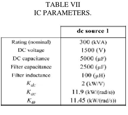
TABLE VII IC PARAMETERS.
REFERENCES
[1] F. Katiraei, M. R. Iravani, A. L. Dimeas, and N. D. Hatziargyriou, ―Microgridsmanagement: control and operation aspects of microgrids,‖IEEE Power Energy Mag., vol. 6, no. 3, pp. 54–65, May/Jun. 2008.
[2] R. H. Lasseter and P. Paigi, ―Microgrid: A conceptual solution,‖ inProc. IEEE-PESC’04, 2004, pp. 4285–4290.
[3] H. Nikkhajoei and R. H. Lasseter, ―Distributed generation interfaceto the certs microgrid,‖ IEEE Trans. Power Del., vol. 24, no. 3, pp.1598–1608, Jul. 2009.
[4] F. Katiraei and M. R. Iravani, ―Power management strategies for a microgridwith multiple distributed generation units,‖ IEEE Trans. PowerSyst., vol. 21, no. 4, pp. 1821–1831, Nov. 2006.
[5] C. K. Sao and P. W. Lehn, ―Control and power management of converterfed microgrids,‖ IEEE Trans. Power Syst., vol. 23, no. 3, pp.1088–1098, Aug. 2008.
[6] I.-Y. Chung, W. Liu, D. A. Cartes, E. G. Collins, Jr, and S. Moon,―Control methods of inverter-interfaced distributed generators in a
microgridsystem,‖ IEEE Trans. Ind. App., vol. 46, no. 3, pp. 1078–1088,May/Jun. 2010.
[7] N. Eghtedarpour and E. Farjah, ―Control strategy for distributed integrationof photovoltaic and energy storage systems in dc microgrids,‖J. Renewable Energy, vol. 45, pp. 96–110, Sep. 2012 .
[8] L. Xu and D. Chen, ―Control and operation of a DC microgrid withvariable generation and energy storage,‖ IEEE Trans. Power Del., vol.26, no. 4, pp. 2513–2522, Oct. 2011.
[9] M. E. Baran and N. R. Mahajan, ―DC distribution for industrial systems-opportunities and challenges,‖ IEEE Trans. Ind. App., vol. 39,no. 6, pp. 1596–1601, Nov./Dec. 2003.
[10] N. Eghtedarpour and E. Farjah, ―Distributed charge/discharge controlof energy storages in a renewable-energy-based DC microgrid,‖ IETRenew. Power Gen., vol. 8, no. 1, pp. 45–57, Jan. 2014.
[11] D. Bo,Y. Li, Z. Zheng, and L. Xu, ―Control strategies ofmicrogridwithhybrid DC and AC buses,‖ in Proc. 14th Eur. Conf. Power Electron.Appl. (EPE 2011), pp. 1–8.
[12] A. Karabiber, C. Keles, A. Kaygusuz, and B. B. Alagoz, ―An approachfor the integration of renewable distributed generation in hybrid DC/ACmicrogrids,‖ J. Renewable Energy, vol. 52, pp. 251–259, Apr. 2013.
[13] K. Kurohane, T. Senjyu, A. Yona, N. Urasaki, and T. Funabashi, ―Ahybrid smart AC/DC power system,‖ IEEE Trans. Smart Grid, vol. 1,no. 2, pp. 199–204, Sep. 2010.
c e-ISSN: 2348-6848, p- ISSN: 2348-795X Volume 2, Issue 11, November 2015
International Journal of Research (IJR)
Available at http://internationaljournalofresearch.org
[15] M. N. Ambia, A. Al-Durra, and S. M. Muyeen, ―Centralized powercontrol strategy for AC-DC hybrid microgrid system using multi-converterscheme,‖ in Proc. IECON 2011—37th Annu.Conf. IEEE Ind.Electron. Soc., Nov. 2011, pp. 843–848.
Mr. P.D.V.S.K.KISHORE was born in India in the year of 1979.He received B.Tech degree in Electrical and Electronics Engineering in the year of 2002 &M.Tech degree in Power Electronics and Industrial drives in the year of 2010 from JNTUH, Hyderabad. He was expert in power electronics and power system subjects.He is currently working as an
Asst.Professor in Narasaraopet Engi-neering College,
Narasaraopet, Andhra Pradesh State , India.
Email id:[email protected]
Mr. MITTAPALLI NAVEEN KUMAR MTECH (POWER ELECT-RONICS
AND ELECTRICAL DRIVES) PURSUING IN Nara-saraopet