Performance Evaluation of Wireless Power
Transfer through Various Coil Shapes
R.Karthikeyan1, P.Mahalakshmi2, N.GowriShankar3, S.Elangovan4
Assistant Professor, Dept. of ECE, Velammal Institute of Technology, Chennai, Tamilnadu, India1
Assistant Professor, Dept. of ECE, Shakthi Engineering College, Chennai, Tamilnadu, India2
Assistant Professor, Dept. of ECE, Meenakshi Sundarajan Engineering College, Chennai, Tamilnadu, India3
Assistant Professor, Dept. of ECE, Sree Sastha Institute of Technology, Chennai, Tamilnadu, India4
ABSTRACT: Wireless power transmission is the transfer of power without any physical contact or without any man made conductors. In this paper we introduce the basic concepts of wireless power transfer using electromagnetic induction type and compare the performance changes during using various shapes of coils for transmission and receiving. The results are verified with an experimental prototype.
KEYWORDS:Wireless power transmission, electromagnetic induction, Efficient Communication, System Security.
I.INTRODUCTION
The human dependency on the gadgets such as smartphone and tablets has increased over the decade. People use them constantly to connect with the cyber world through emails, texting and playing online games. For the average user the battery in these gadgets can last up for a day but due to the extensive use of this gadget the power need of the devices increases and manufactures are forced to have big storage capacity which increases the weight and cost of the devices. Public wireless stations charging may be an option to reduce such problems i.e. changing the devices wireless way. Wireless charging has many applications in the medical environment where charger contacts, such as plugs can corrode easily with liquid disinfectants. The intergraded wireless charging can be extensively used for medical instruments can be encapsulated completely which can prevent contamination and risk of corrosion. Wireless power supplies can eliminate many of the risks and quality control issues associated with charger contacts.
The section 2 of the paper gives the overview about the history of the Wireless power transfer and Section 3 explains the working of the inductive coupling. Section 4 explains the implementing method followed in this paper and also Section 5 shapes of the coils used for comparisons. In section 6 the paper is concluded.
II.
HISTORY OF WIRELESS POWER TRANSFERISSN (Print) : 2320 – 3765 ISSN (Online): 2278 – 8875
I
nternational
J
ournal of
A
dvanced
R
esearch in
E
lectrical,
E
lectronics and
I
nstrumentation
E
ngineering
(An ISO 3297: 2007 Certified Organization)
Vol. 3, Issue 10, October 2014
Some of the common form of wireless power charging is done by using direct induction followed by using resonant magnetic induction. Other methods are taking into account electromagnetic radiation in the form of microwaves or laser and an electric wire with natural media. Some of the most common methods used for the wireless transmission of electricity are Electromagnetic induction, Electrostatic induction, Electromagnetic radiation, Microwave method, Laser method and Electrical conduction.
1)Inductive coupling: The resonant coupling [6] effect between coils of two LC circuits enables the wireless power transfer. The maximum efficiency is achieved when distance between the transmitter and receiver is less.
2)Laser: The Laser is a coherent beam of electromagnetic energy where all the waves have the same frequency and phase. NASA [7] used this mechanism to send energy point to point in a line of sight for a remote-controlled aircraft wirelessly. An infrared sensitive photovoltaic cell act as the energy collector to convert Laser to electrical energy. 3)Piezoelectric principle: The piezoelectric effect [8] is the relation between a mechanical stress and an electrical voltage in solids. This method has feasibility of wirelessly transfer energy using piezoelectric transducers capable to emit and collect vibratory waves.
4)Radio waves and Microwaves: For Long distance high power energy transmission Microwaves [9] are ideal choice and Also, there is a whole research field for rectennas which are antennas capable to collect energy from radio waves.
III.ELECTROMAGNETIC INDUCTION TYPE WIRELESS POWER TRANSFER
Inductive coupling consists of placing two coils of wire in close enough proximity to the other such that they act like a weakly coupled air-core transformer as it transfers energy by inductive coupling between its winding circuits ,the magnetic field radiating from the transmitting coil induces current in the receiving coil[10].The wide bandwidth associated with inductive coupling alone implies lower voltage gain, and thus less power transmitted to the load due to the gain-bandwidth trade off as discussed in. Resonant inductive coupling can be achieved by loading a coil with capacitors so that the inductor-capacitor (LC) combination will resonate at a specific frequency[11]. The narrow bandwidth and higher gain associated with resonant coupling will improve power transfer efficiency. Using inductive coupling power can be transferred only in short distances (upto 10cms).
Advantages of Inductive Coupling:
(a) Simple Design – The design is very simple in theory as well as the physical implementation. The complexity of the circuits built is less and the component count is very low too.
(b) Lower Frequency Operation – The operating frequency range is in the kilohertz range. This attribute makes it easy to experiment and test in breadboard. Furthermore there is low risk of radiation in the LF band.
(c) Low Cost - The entire system is designed with discrete components that are readily available. No custom order parts were necessary for the design.
(d) Practical for Short Distance – The designed system is very practical for short distance as long as the coupling coefficient is optimized.
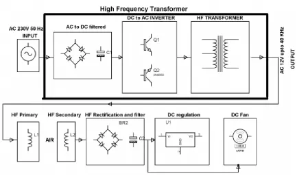
IV.IMPLEMENTING METHOD
Fig. 1 Implementing Block diagram
The Parallel-parallel and series-series compensations are discussed in the literature[12,13] are the basic structures in this paper we take the series-series compensation to demonstrate CT. Figure 2 shows the equivalent circuit model of a system with two coils, in which, RS, R2(R3), L2(L3), C2(C3), M23 and RL represent the internal resistance of the voltage source, the coil parasitic resistances, the coil self-inductances, the resonant capacitors, the mutual inductance and the load resistance, respectively.
Fig. 2 Equivalent diagram of Inductive coupling coils.
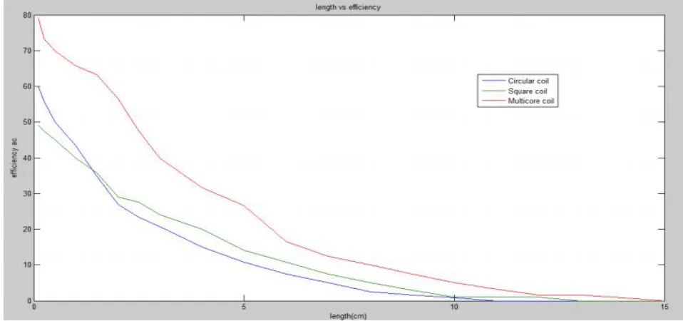
Different shapes of coils were used in implementing our project and for finding efficiencies of the respective coils reading were taken and were plotted using MATLAB.
ISSN (Print) : 2320 – 3765 ISSN (Online): 2278 – 8875
I
nternational
J
ournal of
A
dvanced
R
esearch in
E
lectrical,
E
lectronics and
I
nstrumentation
E
ngineering
(An ISO 3297: 2007 Certified Organization)
Vol. 3, Issue 10, October 2014
Fig. 3Various types of Coils used for experiment.
V. COMPARISON OF COILS
The transmission and received coil is kept in straight line and input supply is fed to the transmission coil. The distance between the two coils is kept low at the beginning and increased further while the transmitted voltage is measured at the receiving end. The experiment is continued further by changing the different types of coils with changing coil shapes.
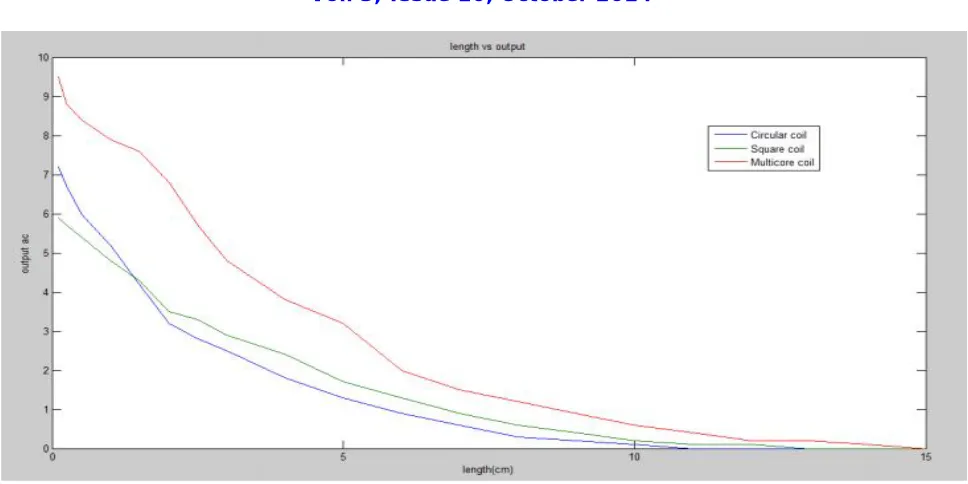
Fig. 5 output energy transmitted vs length between two coils.
VI.CONCLUSION
In this paper wireless power transfer using electromagnetic induction type and compare the performance changes during using various shapes of coils for transmission and receiving. The results shows that the circular twisted pair of coil higher performance while compared to other shapes of coil. The performances of the coils are plotted in graph by using the prototype models of the coils.
REFERENCES
[1] Brown, W.C. The history of power transmission by radio waves. IEEE Trans. Microw. Theory Tech.1984, 32, 1230–1242.
[2] Brown, W. Experiments in the Transportation of Energy by Microwave Beam. In Proceedings of the IRE International Convention Record, New York, NY, USA, 21–25 March 1966; pp. 8–17.
[3] Glaser, P.E. Power from the sun: Its future. Science 1968, 162, 857–861.
[4] Brown, W.C. Status of the microwave power transmission components for the solar power satellite (SPS). IEEE Trans. Microw. Theory Tech. 1981, 29, 1319–1327.
[5] Kurs, A.; Karalis, A.; Moffatt, R.; Joannopoulos, J.D.; Fisher, P.; Soljacic, M. Wireless power transfer via strongly coupled magnetic resonances. Science 2007, 317, 83–86.
[6] Basset, P., Andreas Kaiser, B. L., Collard, D. &Buchaillot, L. (2007). Complete systemfor wireless powering and remote control of electrostatic actuators by inductivecoupling,IEEE/ASME Transactions on Mechatronics12(1).
[7] NASA (2003). Beamed laser power for uavs,Dryden Flight Research Center
[8] Hu, H., Hu, Y., Chen, C. & Wang, J. (2008). A system of two piezoelectric transducers and a storage circuit for wireless energy transmission through a thin metal wall,IEEE Transactions on Ultrasonics, Ferroelectrics, and Frequency Control55(10).
[9] Glaser, P. E. (1973). Method and apparatus for converting solar radiation to electrical power,U.S.A Patent.
[10] Sample, A.P.; Meyer, D.A.; Smith, J.R. Analysis, experimental results, and range adaptation of magnetically coupled resonators for wireless power transfer. IEEE Trans. Ind. Electron. 2011,58, 544–554.
[11] Raju, S.; Wu, R.; Chan, M.; Yue, C.P. Modeling of mutual coupling between planar inductors in wireless power applications. IEEE Trans. Power Electron. 2014, 29, 481–490
![2,3 Dihydro 1H pyrrolo[1,2 a]indole 9 carbonitrile](data:image/gif;base64,R0lGODlhAQABAIAAAP///wAAACH5BAEAAAAALAAAAAABAAEAAAICRAEAOw==)