7671
LAYOUT AN INEXPENSIVE ELLIPTICAL POLARIZED
PRODUCTIVE INTEGRATED TRANSCEIVER
1LWAY FAISALABDULRAZAK, 2FAHAD LAYTH MALALLAH
1Lecturer, Computer Science Department, Cihan University- Slemani, Sulaimaniya, Iraq
2Computer and Information Technology / Engineering Collage Ninevah University, Mosul, Iraq
E-mail: 1[email protected], 2[email protected]
ABSTRACT
This paper reveals a detailed modeling and simulation of active transceiver with elliptical polarization. Simplifying the complexity of merging these components: amplifiers, coupler, patch antenna and power divider using ADS (Advanced Digital System) software to have a system operates at 2.4GHz with less than -11dB return loss. By connecting the proposed transceiver components, it was found that antenna bandwidth was varying from 60o to 70o for both H and E plan. While a 3dB extra power was the gain of designed Active Transceiver above the Passive one.
Keywords: Active Integrated Transceiver, Elliptically Polarization, 2.4ghz Frequency Band, Wireless, Parasite Components
1. INTRODUCTION
A full package of antenna system included in one transceiver experienced is an increasing interest for most of the specialists who want to reduce the cost and size, and increase the overall system performance. Consequently, such a system is tremendously required for indoor WLAN (Wireless Local Area Network) at 2.4 GHz frequency band. A few good assumptive backgrounds had enriched this kind of paper with a large information on simulation actions and adjusting validation especially with the resultant return loss, gain and T-junction isolator between transmitted and received channels. Practically, an excellent prototype is not improved yet. Therefore, this paper will certainly prove that pragmatically as well as discuss the integration process step by step, until we reach the optimum combination between the both transmit and receive channels.
Items are identified are: four sides patch antenna in a diamond shape, T-junction electronic power divider, two Electronic MOSFET amplifier for Rx and Tx channels, and rat-race coupler. All these items simulated individually with ADS software from Agilent. Afterward we tend to match these items together and progressed through fabrication process to have a resonant frequency at 2.4GHz.
An elliptically polarization radiation pattern was obtained by simulation and measurements results. However, the antenna was tested in both
transmitting and receiving mode after the items integration. This work has limitation in power consumption as well as long time of modeling.
Properly this research paper was arranged into eight sections: introduction, literature review, elements aspects specifications and design simulation, Full design assembly, fabrication process, radiation pattern, gain and power strength measurements results for passive elements, radiation pattern measurement for whole antenna analysis in the active case, validation of elliptical polarized antenna with the monopole antenna, and eventually we closed this article by a conclusion.
2. LITERATURE REVIEW
Recently, a great revolution happen in the field of active transceivers design, fully integrated package of communication system appeared in 1928 for the first time [1]. Just then, the electronic tube used with 1 MHz frequency carrier for wireless communication. In 60's and 70's of last century when transistors materialized for high frequency necessity of active transceivers was urgent, it has popped up to cover the markets needs at that time. Many benefits of active transceiver were discussed in [2]. More complexities were discussed in [3], However a functions of receiving components
simultaneously integrated with the active
7672 very interesting for many researchers at 2 GHz frequency carrier especially when full size had been reduced in the proposed design. Another design was proposed in [4], where diode operates at the top of antenna as a mixer, they interdicted the frequency mixer (FET), while Frequency mixer was used to cutoff higher frequencies. Antenna cavity was supported by special type of diodes named Schottky, by mixing radio with the power a good signal could be detected with minimum needs of connection devices. Proposed structure was highly interested for many purposes like radar system wireless communications and paging systems.
Linearly polarization and simultaneous
progression was presented in [5], where Active elements are positively sighted with dual array operations in receiving and transmitting devices it resonant at 4GHz. linear polarization was the most important feature of the radiation pattern on the antenna array, So the transmitting channel was perpendicular with the receiving channel and channel offset could be different base on type of communication channel used.
An integrated hybrid design was mentioned in [6] where Integrated nonlinear Active component had been designed and analyzed for Transmitting and signal reception. The antenna resonant at 2 GHz and Bipolar Transistor was used for the circuit fabrication. While measurements were compared using two different finite domain time difference models. Good circular polarization was mentioned in the results with above than 25dB in the main beam location. A novel idea in [7] suggested separating the transceiver ports as much as possible in the integrated design. The design named Dual Polarized Microstrip patched antenna with a forward feeder, the forward feeder has significantly gave a good overall performance resultant from the isolation. The main reason behind this suggestion was to increase the performance by reducing the thermal noise level especially when single frequency was used.
A terrific optical lively antenna employing integrated FET inverted reel line repair, was provided in [8]. Good return loss and radiation patterns were very obvious in this design. However, the intensity of mixer diode was changed to get an impedance matching with the patch in order to produce 6dB gain. It was found that received signal to noise ratio (SNR) was function to rectified DC voltage while the FET Diode was off. The work defined in [9] was a circuit modulation influenced by Adjustable NP Diode encapsulated within a microstrip plate of antenna with parasitic
components. These strengthen the antenna includes, depending on canal diode prejudice voltage. The outcomes extracted from antenna radiation pattern illustrate that a production of 5.8 MHz in bandwidth could be realized if a small modifications in tunnel diode is loaded. An active microstrip slot-ring antenna was proposed in [10] for the reception of FM microwave indication. Specialists discovered that monolithic behavior of an active slot-ring antenna as a lock-in amplifier. Hypothetical study coupled with fresh outcomes shows works well in a multi-channel setting because of the outstanding noise-squelching home of your shot Locked Gunn Oscillator.
Right now there had been several discussions specifically in [11] when a folded slot machine active point antenna pertaining to 5.8GHz radio applications is provided. It gifted a 10 dB return burning bandwidth of 5.65-6.55 GHz. The research workers claim that a fantastic agreement amongst the simulated and measured final results is discovered. It has great things about compact proportions and bigger bandwidth than previously reported structures.
Portrayal of active integrated antennas in terms of inters modulation distortion and compression place inside of a parallel plate cell was presented in [12]. Some decent commitment amongst the two solutions shows that the evaluation on the overall linearity behavior of arbitrary intricate integrated antennas and can function a contrasting tool in the event the common advised process may not be applied. Through integrating a good pair of zeroth-order resonators with some cross-coupled pair, initially a zeroth order oscillatory active built-in antenna (AIA) was developed in [13]. The proposed AIA, functional at 0.92 GHz, give an excellent DC-to-RF ratio of 52%, a Effective Isotropic Radiation power (EIRP) of 8.9 dBm, and a minimum phase noise of -124.7 dBc/Hz at a 1000 KHz offset adjacent to the carrier frequency. Some patch antenna and category B electrical power amplifier will be integrated pertaining to size decline and substantial power improved efficiency through
harmonic suppression in [14]. Harmonic
7673 increased harmonic controlling slits for anyone protected polarizations.
We present here a full design, simulated, evaluated and executed in a high level of functionality. The proposed design gives a low-cost full layout of transceiver depending on previous techniques viewed in the literature. It is found base on literature that a good evolution is possible to achieve and a promising design of transceiver base on active elements layout is an urgent need to fulfill industry requirements.
3. ELEMENTS ASPECTS, SPACIFICATIONS AND DESIGN SIMULATION
Designing an active integrated transceiver with a low cost is a target of this step, and then it is necessary to list down component of transceiver which are: Transistors, Coupler, Power divider and Circular Polarization Patch Antenna, Technology of amplifiers with basing circuit is empowered on this design using two transistors. Whereas the power divider designed with T-Junction shape to connect the input/output ports with the transceiver channels. An electronic circuit of Rat-race usually used to connect the emitter to the microstrip transmitter; in addition to that it is widely used to separate transition and reception channels [15][16].
Light weight and low profile and cost along with an acceptable radiation pattern are the good advantages of microstrip antenna. Accordingly in recent years an impressive research work emphasized on developing the production of these types of antennas. The Microstrip narrow bandwidth could be an authentic weakness due to the low profile characteristics. Therefore, it is important to mention that antenna bandwidth is a sub-factor of patch territory like: thickness, height, resonance frequency, and substrate dielectric constant [17][18].
In order to calculate microstrip width, the equation is given as follows in (1):
r
f
c
w
2
(1)Where c is light speed, f = operating frequency at
2.40 GHz and
ε
r = 4.60 .It is found that the widthshould be 2.9140 cm. Bt knowing that height h-1.6mm, Consequently we can calculate the Effectiveness of dielectric constant and Cutback for each edge Δ as following in (2) and (3):
W
H
r r eff10
1
1
2
1
)
1
(
2
1
(2)We got: εreff = 4.2460,
8130 . 0 / 2580 . 0 2620 . 0 / 30 . 0 4120 . 0 H W H W H eff eff
(3)We got: Δ=0.073cm. In view of that we can easily bring to a close the length value using the following equation (4):
2
2
f
effc
L
(4)Then, we got: L=2.8870cm
7674
Figure 1: Microstrip antenna has a rectangular shape.
[image:4.612.93.295.158.332.2]With a 0.3cm edge cutting we can get the final diamond shape of our design as in Figure 2:
Figure 2: Diamond shape antenna with a cutting one corner.
The effects of S11 finite method were definitely
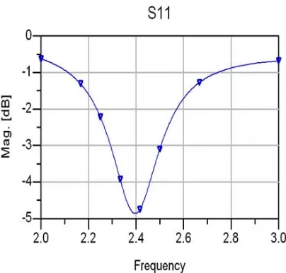
revealed in Figure 3 just for the square block antenna configuration. The antenna designed in a good schematic unit to reach -4.9dB at 2.4GHz frequency range accordingly a nice tuning happen to produce good layout.
[image:4.612.92.294.469.662.2]
Figure 3: S11 simulation results for square antenna Layout
It was found base on simulation results appeared
from Figure 2, that S11 is -3.780dB, and pulse
signaling impedance was 122.00 Ohm (ZL).
To boost up the return loss S11, we applied the
following equation (5):
0 0 11
Z
Z
Z
Z
S
L L
(5)A sector with a 25% of wave transformer introduced between transmission line and microstrip, this addition has improved the overall
antenna return loss. The impedance of ZL and Z0 are
reveled and impedance of quarter waving
transformer ZT is 78 Ohm. Referencing to these
values by LineCalc prick in ADS, the approximate
microstrip width of (W2) and length of (L2) we
determined to be: W2=1.22 millimeter, L2 =17.3
millimeter.
The simulation results of the printed antenna
layout and central circular polarization (S11) were
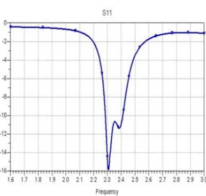
issued and demonstrated in Figure 4 and Figure 5, respectively.
With a width of microstrip width (w) of 30
millimeter, and length (L) of 28.5 millimeter,
7675
[image:5.612.97.421.60.582.2]
Figure 4: The Circular polarized antenna layout.
Figure 5: The return loss (S11) simulation results.
While in Figure 5 the obtained return loss reached to -16 dB, this return loss was functional within the range of 2.28 GHz until 2.41 GHz.
[image:5.612.315.522.114.236.2]By simulating the square antenna using ADS software, it appears that the radiation pattern was not perfectly circular. That leads to a very obvious outcome which is the radiation pattern is more to be elliptical as shown in Figure 6.
Figure 6: Elliptical polarization issued after simulated the radiation pattern of proposed square antenna.
This result in a fact is very effective in the antennas markets. However, having an elliptical radiation pattern makes the antenna behave to be a semi-omni direction. This is very favorable for indoor wireless local area communications.
Since a good results issued, times come to move for fabrication process, the FR4 materials had been used and etched using chemical materials to generate the parts of transmitter. Components were added to the design like couplers, mixers, modulators, Automatic signal level controller (ASLC), and double hybrids which are necessary to combine or separate signals. These components have a good voltage standing wave ratio, typical resistance and insertion loss with a good directivity over bandwidth [19].
With 1800 (1π) phase difference between the
output signals the Hybrid was designed which is similar to the 1/2 π except one different in phase.
Figure 7 shows the behavior of rat-race elements
for 1800 hybrid. As the Ring characteristic
impedance calculated by (2* Zo)0.5 for -3dB hybrid,
where Zo is the calculated value of the input and
output impedance ports.
However, using Rat-Race coupler will allow us to connect both transmitter and receiver channel simultaneously and keep these channels separated
for the same antenna. Accordingly, ZR (Ring
impedance) will be calculated as: (2* Zo)0.5= 70/71
Ω. This value had been used in the simulation of
ADS system.
[image:5.612.93.295.390.582.2]7676
[image:6.612.93.305.67.293.2]Figure 7: The Rat-race coupler design
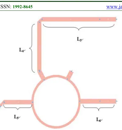
[image:6.612.94.523.69.279.2]Following collecting all basic calculations of rat-race metal coupler is simulated with schematic unit which is demonstrated in Figure 8 and presented in well done form as in figure 9 along with the proven physique.
Figure 8 Schematic circuit mapping of Rat-race coupler.
Figure 9: Schematic simulation to highlight the axial ratio effect of rat-race coupler.
The designed Ring width was 0.15 cm, while the quarter wavelength was calculated to be 1.724 cm, with a 3.292 cm diameter. The result of the residual incrimination in 3 ports length of the transmission line rely on the tuning options to achieve the toning compatibility in L3 , L4 ,L5 ,L6 ,W3 and Radius.
Final Simulation Results:
W3 = 0.153 cm, L3 = 5.226 cm
L4 = 3.118 cm, L5 = 2 cm
L6 = 2.585 cm, Diameter = 3.296 cm
For rat-race coupler phase (s-parameters), it is desirable to mention that the S42 was -90. 3 intended for 2.4GHz volume transporter and 12 was varying around 90.24dB. These values show the best response to the design and style dimensions of rat-race coupler component. However, Rat-race component was fabricated using a FR4 materials and modeled microstrip measured using wet etching technique for the microstrip plate, and outcomes evaluated using Network Analyzer.
Upcoming element is definitely the T-Junction electrical power divider panel, the following factor is vital to link up the transmitted and received alerts combined together with the input/output plug-ins (ports). With this research implemented impedance intended for T-Junction electric source divider was
Z=70.7Ω, as determined priory. Although this
[image:6.612.89.301.400.613.2]7677
[image:7.612.90.294.285.420.2]Figure 10: The schematic scheme of designed T-Junction produced by ADS software.
Figure 11: The Layout scheme of designed short T-Junction produced by ADS software.
To be able to match T-Junction electrical power divider panel considering the whole effective antenna enterprise, the diffusion line part should be higher which is portrayed in Figure 12, the tuning
solutions for L7, L8, L9, W4 the ranges changing
though tuning finite result is normally found with Figure 13. However, Final Simulation Results for
the extended mentioned parameters were: W4 =0.15
cm, L7 = 1.452 cm, L8 = 0.843 cm, L9 = 1.756 cm.
Figure 12: longer adjusted transmission line produced by ADS software.
Figure 13: Scattering-parameters simulation results produced by ADS software for T-junction electronic
power divider
Undoubtedly, S21 and S31 values are changing
while L8 is tuned, and S21 and S31 values are
changing while L7, L8, L9 is tuned.
T-junction electronic power divider panel can be then fabricated with a microstrip items (FR4) using soaked chemical etching approach, proper measurements done using Networking Analyzer to validate the results.
[image:7.612.315.519.358.536.2]7678 First combination done without adding patch antenna it was modeled by connecting the coupler to the amplifier. Nevertheless, the objective of such a combination was simulating two spited channels for the transmitting and reception. Whereas in second stage our objective was simulating the gain of transmitting channel as well as the gain of receiving channel using the transceiver which is the antenna.
[image:8.612.316.523.87.217.2]The combining of coupler and amplifier may be taken out quickly in schematic style design since viewed with Figure 14, where rate-race coupler have a good position in four ports data item as well as the amplifier is definitely shaped simply by two jacks data item.
Figure 14: Coupler and amplifier combination of in ADS software
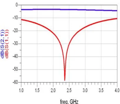
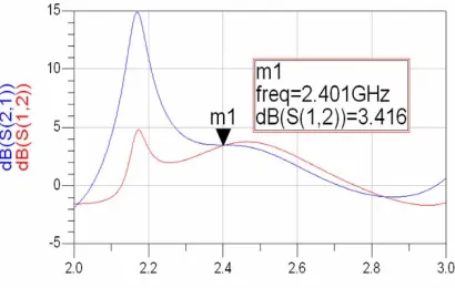
The coupler scattering parameters is imported as a data Item from the simulated graphs. The amplifier scattering parameters was an input into a Mini-circuit file first and then imported into Data Item from this file. Simulation result is shown in
Figure 15.
The scattering parameters of coupler were brought in into Info Item through the ruse chart file. The amplifier scattering parameters were insight into Mini-circuit record first after which imported in to Information Item from this data file. Simulation effect is demonstrated in Figure 15.
Figure 15: Simulation results of scattering parameters of coupler isolation
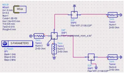
[image:8.612.90.298.294.417.2]Combining all the designed components except the antenna was depicted in Figure 16, where a schematic sketch simulation used to elaborate the circuit components. T-junction power divider with a three ports had been adding to the simulation and the results of s- parameters could be extracted from figure 16.
Figure 16: Whole circuit except antenna in ADS software
Figure 17 shows the abilities of obtaining good
S-parameters after tuning L9 to gain a good
performance from the transmitted and receiving channel.
[image:8.612.314.523.376.514.2]7679
Figure 17: Adjustable L9 values to get the best gain the Rx and Tx channels.
[image:9.612.92.297.344.474.2]The simulated axial ratio response throughout the resonant band is necessary to validate the performance of elliptically polarized antenna.
Figure 18: Tx and Rx gain simulation results.
5. FABRICATION OF LAYOUT AN INEXPENSIVE ELLIPTICAL POLARIZED PRODUCTIVE INTEGRATED
TRANSCEIVER
The final layout an inexpensive elliptical polarized productive integrated transceiver is shown in figure 20, the passive plate patch, capacitor and resistor components ports and conductive elements are fixed by soldering on the FR4 plate.
Figure 19: layout an inexpensive elliptical polarized productive integrated transceiver.
A wet chemical etching used to fabricate the Rat-race ring with the FR4 plate, while the measurements done using Marconi device and network Analyzer.
Adding the T-Junction power divider will facilitate the input and output ports and connect them to the received and transmit channel, it was
found that best impedance could be Z=70.71 Ohm,
while Z= (2*Zo)^1/2. It is worthy to mentioned that
the transformer quarter wave length of the
transmitter (W4) was 0.15 cm while the 1/4 wave
length was 1.724cm.
By initiating all required formulas it was found that the scheme of T-junction power divider has the
following values: L9 = 1.756cm, L7 = 1.452, W4
=0.151 cm, cm and L8 = 0.843 cm, these
dimensions values of T-Junction power divider were used in the fabrication process by wet etching technique and Network Analyzer. The design assembly is depending on adding the whole circuit without the antenna; combination will include the coupler and the amplifier to simulate the isolation of received and transmitted channels, then to find the channel proper gain.
6. RADIATION PATTERN, GAIN AND POWER STRENGTH MEASUREMENTS RESULTS FOR PASSIVE ELEMENTS
7680
[image:10.612.268.515.66.331.2]Figure 20: Measurement of antenna radiation pattern setup.
Figure 20 shows that Active antenna used as a transmitter and the signal received by a horn antenna (the reference antenna). This scenario will be reversed in a case when the active antenna used as a receiver. A DC motor mounted directly under the fabricated Integrated Active Antenna and used to give rotation torque and allow us to measure the resultant polarization [20].
Figure 21 and 22 show the measured radiation pattern of the fabricated active integrated antenna, we found a good and wide coverage can produced by shedding this antenna power on the anechoic Chamber area.
[image:10.612.91.315.72.254.2]Figure 21: Radiation pattern of the Passive Antenna for E-copolarization
Figure 22: Radiation pattern of the Passive Antenna for H-copolarization.
Bothe H-Plane and E-Plan have 700 of Half
Power Beam Width (HPBW). It is clear from the H-plane and E- H-plane that there are no much differences between both patterns, and we found that the co-polarization is very similar to the cross polarization which make us admit that this antenna is circular polarized antenna. Figure 23 shows the
return loss S11 of the circular polarized passive
[image:10.612.93.294.465.704.2]antenna was measured using the Network Analyzer.
Figure 23: The measures Return loss in comparison with the simulated result.
[image:10.612.314.520.478.649.2]7681 and it is attractive for many applications. As a good outcomes obtained from ADS Simulation had shown an excellent harmonization with the fabricated design. The achieved return loss (S11) in ADS simulation was -22dB at centre frequency of 2.4GHz. On the other hand, bandwidth was improved in a better way. However, the phase different from port 4 until port 2 (-90o) and phase
different from port 1 to port 2 (90o) is 180o. The
obtained Return loss after measurements was -24dB at 2.4GHz, the phase difference from port 4 to port
2 (-107.5o) and port 1 to port 2 (77.5o) is 185o which
is almost 180o.
Validating the estimated comes from the
simulation using ADS by the reaction
measurements after fabrication process a
great result appeared. In term of Return loss, a good result of lower than -15.5 dB harvested at 2.4GHz with an impressive Bandwidth (BW). The measured gain from port 1 to port 2 and port 1 to port 3 was -4.6 dB (46.5%), which reflect a wise choice of material used because of good harmonization with the simulation results. The amplifier circuit was connected to 68 Ohm resistor and 1x10⁻¹⁰ Farad capacitor to an ATF transistor to achieve the bases, all together was soldered in one line and connected to the pitch.
7. RADIATION PATTERN
MEASUREMENT FOR WHOLE ANTENNA ANALYSIS IN THE ACTIVE CASE
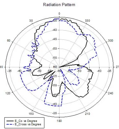
[image:11.612.316.517.90.309.2]The whole system radiation pattern was demonstrated in Figure 24 and 25, for Active Integrated Antenna, and the measurements had been done inside the anechoic chamber.
[image:11.612.104.282.518.713.2]Figure 24. The H-plane of return loss in Active mode.
Figure 25. The E-plane of return loss in Active mode.
The Active mode radiation pattern analysis shown in Figure 24 and 25 emphasize that the antenna has an almost symmetrical cross polarization because both of H-curve and E-Curve are alike.
When a validation applied between active and passive results, we found that passive results are better because of the Transistor instability, which cause a reduction in the transmitted power at some points. For this Active antenna the HPBW as a
transmitter was 670 for E-plan and 640 for H-Plan.
On the reception side the HPBW was 650 in E-Plan
and 620 for H-Plan.
8. VALIDATION OF ELLIPTICAL POLARIZED ANTENNA WITH THE MONOPOLE ANTENNA
7682
Figure 26: Comparing the gain of monopole antenna with the current active antenna gain.
Figure 27: Comparing the gain of monopole antenna with the current active and passive antenna gain.
9. CONCLUSION
The aim of this research is in conformity with occurrence format on Integrated Microstrip Active Transceiver, T-junction Power Divider, special Rat-race Coupler, and Amplifier’s Biasing with the
utilization of ADS software, yet using these
designs in accordance with construct prototype. All those Prototypes have already been examined to check on their capability to produce successful, powerful and solid item. All designs had been simulated analyzed built fabricated and measured in a good form of integrated antenna. A good gain issued from the integration process, improving such a gain will lead to a very impressive technology would help to reduce the weaknesses of MIMO antennas systems. Ultimately, this research was specially designed and fabricated successfully on single plate intends is compatible with the planned objectives.
REFRENCES:
[1] H. A. Wheeler, Fundamental limitations of
small antennas, Proceeding of IRE, vol. 35, 1947, pp. 1479-1484.
[2] J. R. Copeland, W. J. Roberston, and R. G.
Verstraete, Antennas-verters and antennafier arrays, IEEE Trans. Antennas Prop., vol. AP-12, 1964, pp.227-233.
[3] K. Kurokawa, Active integrated antenna
technique, Proc. IEEE, Vol. 2 No. 1, 2004, PP:133-140.
[4] Yexi Song, Yunqiu Wu, Jie Yang, Yin Tian,
Wei Tong, Yijun Chen, Cetian Wang, Xiaohong Tang, Johannes Benedikt, Kai Kang, A Compact Ka-Band Active Integrated Antenna With a GaAs Amplifier in a Ceramic Package, Antennas and Wireless Propagation Letters IEEE, vol. 16, 2017, pp. 2416-2419.
[5] Philippos Assimakopoulos, Vitawat Sittakul,
Anthony Nkansah, Nathan Gomes, Martin Cryan, David Wake, Comparison between remote Antenna Units with Detachable antennas and Photonic Active Integrated Antennas for indoor applications, General Assembly and Scientific Symposium 2011 3rd URSI, 2011,pp. 1-4.
[6] Wenzhang Wang, L.W. Pearson, A highly
controllable MESFET active patch
antenna/oscillator, Antennas and Propagation Society International Symposium. IEEE. Digest, vol. 1, 1997, pp. 34-37.
[7] S. L. Karode, Dual Polarized Microstrip Patch
Antenna Using Feedforward Isolation Enhancement for Simultaneous Transmit receive Applications, IEE National Conference on Antennas and Propagation, 1997, pp. No. 461-469.
[8] J. A. Navarro, L. Fan and K. Chang, Novel
Quasi-Optical Active Antenna Using Integrated FET Inverted Stripline Patch, Electronics Letters, No. 8, 1994, pp. 655-657.
[9] Rakesh N. Tiwari, Prabhakar Singh, Tunnel
Diode Loaded Microstrip Antenna with Parasitic Elements, Journal of Electromagnetic Analysis and Applications, vol. 04, 2012,pp. 177.
[10] S. Chatterjee, B. N. Biswas, Active
Slot-Ring Antennas As A Receivers, Progress In Electromagnetics Research Letters, Vol. 32, 2012, pp.59-68.
[11] Sudhir Bhaskar, Sarthak Singhal, Amit K.
[image:12.612.93.291.276.418.2]7683
[12] Evgueni Kaverine, Sebastien Palud,
Franck Colombel, Mohamed Himdi,
Dominique Lemur, Intermodulation Distortion and Compression Point Measurement of Active Integrated Antennas Using a Radiative Method, Progress In Electromagnetics Research M, Vol. 54, 2017, pp.145–152.
[13] Yu Wei Chang, Tzyh Ghuang Ma,
ZerothOrder SelfOscillating Active Integrated
Antenna Using Cross Coupled Pair, IEEE
Transactions on Antennas and Propagation, Vol.65, No. 10, 2017,pp. 5011 – 5018.
[14] Ali Khoshniat, Taha Yekan, Reyhan
Baktur, Karl F. Warnick,
Active Integrated Antenna Supporting Linear a nd Circular Polarization. IEEE Transactions on Components, Packaging and Manufacturing Technology, Vol.7, No.2, 2017,pp. 238 – 245.
[15] JOHN WILEY & SONS, INC. RF and
Microwave Wireless Systems. 2000.
[16] Robert J. Mailloux, Phased Array Antenna
Handbook, 2nd ed. British: Publication. 2005.
[17] Girish Kumar K. P. Ray, Broadband
Microstrip Antennas, ARTECH HOUSE, INC. 2003.
[18] THOMAS A. MILLIGAN, Modern
Antenna Design, 2nd ed. A JOHN WILEY & SONS, INC., PUBLICATION. 2005.
[19] Ali K. Aswad, Lway Faisal Abdulrazak
and Tharek Abd. Rahman, Design and
Development of High-Gain Wideband
Circularly Polarized Patch Antenna, Proceeding of IEEE International RF and Microwave Conference, Malaysia. 2008.
[20] Rukmini T S Rao, Performance Analysis
of Wide Band Circularly Polarized EBG
Microstrip Antenna for Base Station
Applications, International Journal of Applied
Engineering Research, Research India