SIMULATION RESULTS ON A NEW NON SYMMET-RICAL COPLANAR ISOLATOR STRUCTURE USING MAGNETIC THIN FILM
S. Kirouane, E. Verney, and D. Vincent DIOM Laboratory
Saint-Etienne University
23 rue Paul Michelon, St-Etienne, Cedex 42023, France
A. Chaabi LHS Laboratory Constantine University
Route Ain el Bey Constantine, Algeria
Abstract—The non reciprocal effect of such devices as microstrip and coplanar isolators can be based on the field displacement phenomenon induced by a magnetized ferrite material. The structure under study is made from a ferrite thin-film deposited on a alumina substrate. A non symmetrical coplanar line is put on the ferrite film and the absorber is made from either a graphite film or a Tantalum Nitride film or a copper slab. In order to work in millimeter wave range the barium ferrite was selected. Moreover, the size of the component could be less than the circulator one. The small size and simple shape are the principal advantages of a coplanar isolator structure.
1. INTRODUCTION
Isolators constitute essential components used in telecommunication systems. A possible way to design isolators suitable for integration consists in using ferrite thin films. To reach millimeter wave band, ferrites having a high magnetocristalline anisotropy must be used (in high frequencies bands from 28 GHz to 40 GHz and 50 GHz to 65 GHz for LMDS and WLAN applications). Moreover, the use of permanent magnets is not allowed and the magnetic material must
be self-biased [1–4] to achieve the passive component integration on a microwave circuit. All efficient non reciprocal components use the field displacement phenomenon to obtain the non reciprocal effect.
One way to create an isolator consists in using a circulator with one matched port. Then, the signal propagation is only possible in the forward direction and not in the backward one. Even if the size of the circulator becomes small in high frequency bands, it should be possible to reduce it by designing a two port component such a line structure isolator. Stripline and microstrip structures were used for making line isolators [5, 6]. However, the coplanar topology simplifies the connections between components and planar low-cost devices can be made.
First, Wen proposed a coplanar isolator [7]. However, in this work, the non reciprocal effect is based on the gyromagnetic resonance phenomenon. Even if a high isolation can be reached, insertion losses still remain too important. Although the author apparently obtained good performances in low frequency bands, they become wrong in higher bands and the component cannot make use.
So, the following structure proposed here, is made from a non symmetrical coplanar line on a ferrite thin-film which was deposited on a alumina substrate. The field displacement phenomenon is used to produce the non reciprocal propagation. The absorber is made from either a graphite film or Tantalum Nitride (TaN) film or a copper slab. In this approach, our objective is not to completely design a component, but to perform a feasibility study. We have no comparison (no reference) between our coplanar structure and microstrip line isolator at this frequency range.
2. COPLANAR ISOLATOR STRUCTURE
3. SIMULATION RESULTS AND DISCUSSION
The results were obtained from Ansoft HFSS software, a three dimensional electromagnetic finite elements simulator.
Figure 1. Cross-sectional view and top view of the coplanar isolator.
45 46 47 48 49 50 51 52 53
-24 -22 -20 -18 -16 -14 -12 -10 -8 -6 -4
S12 S21 S11
Frequency (GHz)
S-parameters (dB)
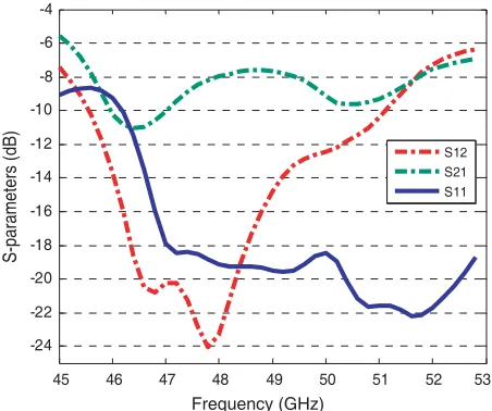
Figure 2. S-parameters of isolator with 100µm graphite absorber and 15µm ferrite thin film and 5 mm isolator length.
The choice of the magnetic material is carried out on barium ferrite. This material has been extensively studied due to its potential applications in recording and millimetre wave devices. This material has a strong uniaxial anisotropy about 1.7 T and a high frequency gyroresonance in the range of 40–50 GHz.
only polycrystalline material without oriented easy axis, so, at this time, without suitable material the first results are simulation results assuming self-biased and mono crystalline magnetic material. Results obtained with a graphite absorber are shown in Figure 2.
The curves show that the structure behavior is the isolator one: there is a great nonreciprocal effect. The isolation reaches 24 dB while the insertion value is 8 dB around 48 GHz. Non reciprocal effect requires the location of an absorber material at one side of the structure. So, an asymmetrical field distribution in the structure and the location of the absorber on one side induce more losses in the backward propagation where a field displacement phenomenon takes place. As expected, this nonreciprocal effect exists only if a perpendicular polarization of the ferrite thin film is applied and if an absorber is located at one coplanar line side. The dimensions of the asymmetrical coplanar line are chosen to keep a quasi-TEM propagation mode [8, 9], as S = 72µm, W1 = 40µm, W2 = 1200µm,
h = 635µm, physical length 5 mm and 100µm thickness of graphite. A taper is added for a good matching (50 Ω).
3.1. Influence of the Applied D.C. Field and the Thickness of the Thin Magnetic Film
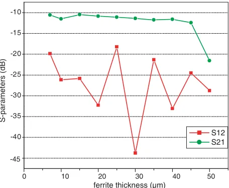
Figures 3 and 4 show the influence of the ferrite thickness and the applied field intensity on the isolator performances. According to these
-100 0 100 200 300 400 500 600 700 800 -26
-24 -22 -20 -18 -16 -14 -12 -10 -8
S
-P
a
ra
m
e
te
rs
(d
B
)
Applied field (mT)
S12 S21
0 10 20 30 40 50
-40 -35 -30 -25 -20 -15 -10
S-par
amet
ers (
dB)
ferrite thickness (µm)
S12 S21
-45
Figure 4. Variation ofS-parameters according to the ferrite thickness (µm) with 100µm graphite-layer thick at 48 GHz.
results, the best performances are obtained when the external applied field value is 500 mT. Even if the insertion losses slowly increase when the thickness of the ferrite film increases (apart from the last point), the non reciprocal effect is better for around 30µm ferrite thickness value.
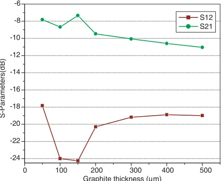
3.2. Influence of the Graphite Thickness and Its Location Results in Figure 5 show the impact of the graphite thickness on the insertion lossesS21 and the isolationS12. The insertion losses increase
with the graphite thickness contrary to the isolation. So, the 100µm thickness value which gives the best result is kept.
Other materials could replace the graphite absorber for improving the isolator performances. So, simulations have been done with Tantalum Nitride and copper (the thickness of copper equal to: 2µm) and the results are shown in Figure 6 and Figure 7.
0 100 200 300 400 500
-24 -22 -20 -18 -16 -14 -12 -10 -8 -6
Graphite thickness (µm)
S-Para
meters(d
B)
S12 S21
Figure 5. Variation of S-parameters according to the graphite thickness (µm) (15µm of ferrite-film thick) at 48 GHz.
porosity. . .). However, the copper thin layer should not be considered as a pure absorber, even if a conductor with a finite conductivity as a pure absorber, even if a conductor with a finite conductivity creates losses.
In our isolator design (see Figure 1), the coplanar line and the thin copper layer constitute a waveguide filled with ferrite on one side of the line. So, when the field displacement takes place (for backward propagation), important losses occur which could due to several phenomenon like gyromagnetic resonance (predominant real part of the propagation constant), magnetostatic waves (forward volume waves) [10, 11] . . . .
The effect of the absorber location has been studied. It was
Table 1. Variation of the insertion losses according to the conductivity of the absorber material. (for bulk at low frequencies).
Materials Graphite TaN Copper Conductivity (Ω−1m−1) 70000 7400 580·106
Insertion losses (dB) 8.19 10.73 5.3
Thickness (µm) 100 100 2
located between the ground plane on one side and the central strip. Results are not presented here but simulations showed that the best absorber position is equal to W1 from the central strip to the right
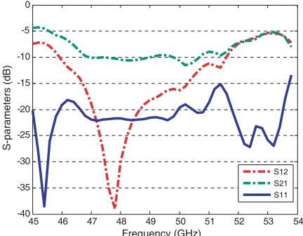
side of asymmetrical transmission line (see Figure 1) under the ferrite thin film. That gives the best performances about the isolation and insertion losses and makes the fabrication of the component easier. The best results are shown on Figure 8 with a copper absorber for 10 mm length and 2µm thickness. Even if the insertion losses still remain too high, (around 10 dB/cm) the bandwidth can be evaluated to 1.5 GHz when the isolation is higher than 20 dB. Although simulations were carried out on the same structure (see Figure 7) the isolator length is increased twofold giving slightly different results. The difference between the curves obtained from the two samples is probably due to the FE software which has to make a new mesh. This is the reason why the Figure 8 is added and permits us to evaluate the bandwidth. On other hand, in order to improve the performances, metamaterials could be used as absorber, since they can create high losses in a fixed frequency range [12]. Results should be presented in a future article. This kind of isolator devices requires oriented barium thin film which is not easily available at present time. That still remains a technological problem to make a prototype and to perform some measurement.
45 46 47 48 49 50 51 52 53
-24 -22 -20 -18 -16 -14 -12 -10 -8
S12 S21 S11
Frequency (GHz)
S-parameters (dB)
45 46 47 48 49 50 51 52 53 -22
-20 -18 -16 -14 -12 -10 -8 -6 -4 -2
S12 S S11
Frequency (GHz)
S-parameters (dB)
21
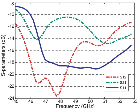
Figure 7. S-parameters of isolator with 2µm copper (absorber) and 15µm ferrite thin film and 5 mm isolator length.
45 46 47 48 49 50 51 52 53 54
-40 -35 -30 -25 -20 -15 -10 -5 0
S12 S21 S11
Frequency (GHz)
S-parameters (dB)
Figure 8. S-parameters of isolator with 2µm copper (absorber) and 15µm ferrite thin film and 10 mm isolator length.
4. CONCLUSION
various values of external applied field has been done from Ansoft HFSS software. Acceptable nonreciprocal transmission characteristics have been obtained. The small size and the linear shape of this isolator is an advantage for MMIC devices. The making of the component is limited because the oriented barium thin film is not easily available at present time. This study must be continued and improved by using oriented BaM ferrite film and carrying out demonstrator device.
REFERENCES
1. Capraro, S., T. Rouiller, M. Le Berre, J. P. Chatelon, B. Bayard, D. Barbier, and J. J. Rousseau, “Feasability of a self biased coplanar isolator with barium ferrite films,” IEEE Transactions on Components and Packaging Technologie, Vol. 30, No. 3, 411– 415, September 2007.
2. Capraro, S., T. Rouiller, M. Le Berre, J. P. Chatelon, B. Bayard, D. Barbier, and J. J. Rousseau, “Exploration of the integration of passive coplanar isolator based on thin magnetic films,” Microwave and Optical Technology Letters, Vol. 46, No. 5, 435– 437, September 2005.
3. Zuo, X. and C. Vittoria, “Self-biased circulator/isolator at millimeter wavelengths using magnetically oriented polycrystalline strontium M-type hexaferrite,” IEEE Trans. Microwave Theory Tech., Vol. 39, No. 5, 3160–3162, September 2003.
4. Pardavi-Horvath, M., “Microwave applications of soft ferrites,” Journal of Magnetism and Magnetic Materials, Vol. 215–216, 171– 183, June 2000.
5. Courtois, L. and M. De Vecchis, “A new class of nonreciprocal components using slotlines,” IEEE Trans. Microwave Theory Tech., 511–516, June 1975.
6. Hines, M. E., “Reciprocal and nonreciprocal modes of propagation in ferrite stripline and microstrip devices,” IEEE Trans. Microwave Theory Tech., Vol. 19, No. 5, 442–451, 1971.
7. Wen, C. P., “Coplanar waveguide: A surface strip transmission line suitable for nonreciprocal gyromagnetic device application,” IEEE Trans. Microwave Theory Tech., Vol. 17, No. 12, 1087–1090, 1969.
including conductor-loss effects,”IEEE Trans. Microwave Theory Tech., Vol. 41, No. 1, 45–52, January 1993.
10. Stancil, D., Theory of Magnetostatic Waves, 101–107, Springer, 1993.
11. Tsutsumi, M., K. Kikui, and T. Ueda, “Characteristics of slot line with yttrium iron garnet substrate and its application,” Proceedings of APMC 2001, 1219–1221, Taipei, Taiwan, R.O.C., 2001.