ISSN 2286-4822 www.euacademic.org
Impact Factor: 3.4546 (UIF) DRJI Value: 5.9 (B+)
Performance Evaluation of the Low Head Type Pico
– Hydro Electric Generating System (LH-PHEGS)
ADRIANO B. SINGIAN Don Honorio Ventura Technological State University Bacolor Pampanga, Philippines
Abstract:
Proper utilization of advance Renewable Energy Technologies such as the modified Low Head Type Pico-hydro Electric Generating System (LH-PHEGS) will reduce monthly electrical bill and increase environmental awareness among the residents. The study was focused on the testing and evaluation of the performance of the LH-PHEGS. Methods of evaluation were based on the data stipulated on the manual of standard and primarily directed on the efficient and reliable supply of electrical power. It took into account the results of the climatological, hydrological and electrical application of the system. The study made use of the on-site evaluation method. The laboratory, library and internet research methods are the primary techniques used. Different parameters of computations, testing and measuring instruments/devices were utilized to attain reliable results and a significant conclusion. The concluded result of the study showed that there is a viable significance in terms of social and economic impact when using the device than the usual commercial grid supplied electric power system. The LH-PHEGS can be utilized to address the minimum off-grid electrical power requirements needed by our marginalized people of rural areas who cannot afford the high cost of commercial electricity but have vast supplies of hydro resources coming from different tributaries.
Introduction
Our society is very much dependent on utilizing imported fossil fueled electrical power source. This and other key findings were discussed in the various technical conferences and symposia. The study finds escalating demand for electricity, coupled with frequent power outages that posed a serious threat especially to the Philippine economy. On the other side, some local power producers cannot strategically provides an open window for an affordable power supply opportunity for the increasing demand of the consuming public especially the small households living in the remote uplands such as the Aetas who up to this time are among the poorest member of the society.
There are two types of energy sources that can be used to produce electric power, the conventional type which uses coal, oil wood and the like and the non-conventional type which uses solar, hydro-electric, wind, ocean , geothermal and others. Conventional sources produce lots of carbon dioxide that adds to the greenhouse effect in the atmosphere, while the non-conventional uses renewable type of energy as they are all free, inexhaustible and emit no carbon dioxide (biomass does, but it prevents the production of methane which is a greenhouse gas 21 times more dangerous than CO2).
tube and three secondary components such as: (a) the debris strainer assembly, (b) the power controller assembly, and (c) the base and brackets as shown in Figure 1.
Figure 1. The modified LH-PHEG System Layout
The LH-PHEGS is a portable hydro-generator being run by the average rapid downpour of water (±70 liters/sec.) coming down from the two main streams at the foot of Mount Arayat in Pampanga, Philippines. The water channel which is made up of GI sheet gauge # 16 will serve as the water reservoir of the system and where the Hydro-Generator assy. is mounted. The turbine/propeller of the machine rotates at an average speed of 247.5 rpm because of the velocity and force of discharged water passing through its fins and directly passing into the drop tube which is also attached at the bottom part of the water channel. The discharged water from the LH-PHEGS then goes into the main canal to be utilized for cascading application and for the irrigation needs of the farmers.
Objectives of the Study
The general objective of this study is to test and evaluate the performance of the modified type of Low Head type Pico- Hydro Electric Generator system in terms of functionality, usability and reliability. Specifically, the study aimed to test and find solutions to the problems: a) efficiency of the electrical power output (quality audit); b), the physical performance of the project; c, noise and vibration condition and d), realize the socio-economic benefits it can create.
Framework
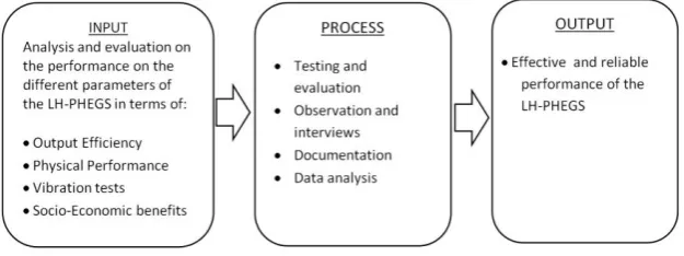
The conceptual model provides the general structure and guide in the development of the study as presented in Figure 2.
Figure 2 Conceptual Framework
Materials and Methods
According to Michael Q. Patton (1990), when one examines and judges accomplishments and effectiveness through careful data collection and thoughtful analysis, one is engaged in evaluation research. The emphasis throughout is on gathering information and generating findings that are useful in evaluating the LH-PHEGS efficiency, while the interviewing, observation, and analysis methods presented in this study are relevant to qualitative purposes. The researcher observed and collected data regarding the installed modified Low Head type Pico Hydro Electric Generating System (LH-PHEGS) used to address the needs of electrical power of the evacuees inside the Arayat National Park in Pampanga, Philippines. First hand data and other significant information were obtained from personnel of the Municipal Social Welfare and Development (MSWD), personnel attending the evacuees, Park Protection and Management Office (PPMO), Provincial Environment and Natural Resources Office (PENRO) and the evacuees to formulate rational and sound basis for the study.
The researcher referred to the book of hydrological standards and other reading references regarding the guidelines required in the system installation of pico hydro-electric generators. Internet and library research were also done along with other data-gathering methods.
The study was conducted with several homogeneous groups of individuals, who served as the primary respondents such as personnel’s from different concern government offices and the evacuees (victims of typhoon Ondoy) where electricity plays an important role in the course of their daily needs and operations.
electric power produced by the LH-PHEGS while the respondents are observing. Thereafter, the respondents did the same procedures as how it was demonstrated.
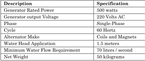
The LH-PHEG System was installed, utilized and tested based on the standard specification as shown in Table 1.
Table 1. LH-PHEG-500 specifications
Three major test categories were conducted in presenting the technical and performance evaluation of the device such as (1) water volume, velocity and displacement test, (2) equipment performance and stability (EPS) test and (3) the on-grid and off-grid power quality audit or (PQA) of the entire power and performance system. Basic electrical hand tools and testing instruments were employed in the electrical circuit installation in testing and determining intrinsic safety performance and efficiency of the modified LH-PHEG system and connected loads.
Water Volume, Velocity and Displacement Test
The 200 cu.m volume of water was computed based on the internal dimensions of the concrete main water reservoir located at the downhill of Mount Arayat at San Juan Baño, Arayat, Pampanga. Water volume displacement was computed in terms of the incoming water volume from the two main water springs and the discharge of water coming out from the two spill-over outlets of the main reservoir as shown in Figure 3.
Description Specification
Generator Rated Power 500 watts
Generator output Voltage 220 Volts AC
Phase Single-Phase
Cycle 60 Hertz
Alternator Make Coils and Magnets
Water Head Application 1.5 meters
Minimum Water Flow Requirement 70 liters / second
Figure 3. The main concrete water reservoir of Arayat National Park.
The water velocity (Wv) from the main stream (as shown in Figure 4) was also computed using the volume of the discharge water (Q) divided by the area of the water stream/channel (Ac). Wv = Q/Ac
Figure 4. The main water stream coming from the main water reservoir
Power and Quality Test
with each other. In other words, the phase angle is zero as shown in Figure 5.
Figure 5. The sinusoidal waveform from the oscilloscope showing voltage and current are in phase and cross the neutral horizontal line (abscissa) concurrently.
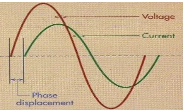
The Power Factor Test
Power Factor (Pf) was also computed to measure how effective the AC system operates. Power factor can be express in two ways; PF = actual power (kW) / apparent power (kVA) or W = V x PF where we used a wattmeter to measure the watts and the ammeter and voltmeter to measure the volt amperes as cosine ϕ. Using inductive loads (electric fans) as test models, the sinusoidal waveform on Figure 6 shows that the current crosses the abscissa after the voltage that cause phase displacement. This displacement relates to the power factor.
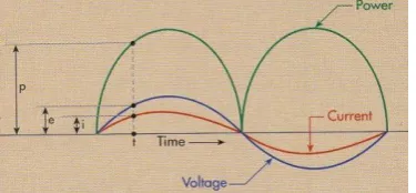
The Energy Loss Test
The product of instantaneous current (i) and instantaneous voltage (e) gives an instant power result. When both “e” and “i” are in the negative part of the abscissa their product (power) is positive. See Figure 7. The system is expending power throughout the cycle and delivering it to the connected loads. Also, for any period of time we applied the power into the loads, there is an expenditure of energy (energy loss) equal to power loss times the time involved. Both of these losses (power and energy) are inherent in the LH-PHEG power system.
Figure 7. The sinusoidal waveform showing the graph patterns of instantaneous voltage (e) and instantaneous current (i) in relation with their instant power product.
The Phase and Power Draw Back Test
Figure 8. The graph patterns between the relationships of phase value of voltage, current and output power.
Pico-Hydro Electric Generator Physical Performance Tests
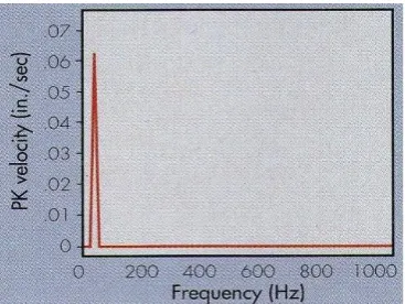
Hydro Generator Vibration Test
Under average water volume and flow rate of 74.52 liters /second during daytime of operations, the vibration test was conducted on the LH-PHEG’s alternator assembly. The graph of the accelerometer tester shows that the velocity and frequency vibration spectrum along with other harmonics of sub components such as bearing stability in the main shafting, alignment and clearances are stable as shown Figure 9.
Figure 9. The amplitude at rotational frequency at water average volume as an indicator of balanced alternator’s rotation
Water Channel Vibration Test
the force and volume of the incoming water from the main stream and the velocity of discharged water from the drop tube. The graph displayed on the monitor of the tester shows that a group of enclosed band-pass changes on different intensity of graduation spectrum as shown in Figure 10.
Figure 10. The graph on the monitor of the tester showing the group of frequency bands that indicates changes on the vibration spectrum of the water channel.
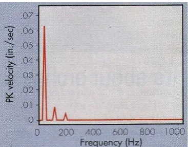
The Vibration Test of the entire LH-PHEG’s System during night time.
Using the average water volume and flow rate of 82.28 liters /second as basis during night time (till dawn) of operation, a vibration test was conducted on the entire LH-PHEG’s assembly. The displayed graphical format on the monitor of the vibration meter tester (PCE-VT 204) on Figure 11 shows that the volume and velocity of the incoming water from the main stream is the primary factor causing the frequency of vibrations. Aside from this, the interaction of equipment’s sub-components such as the machine’s water channel, shafting and bearings and the attached draft tube assembly further contributes to the vibration.
Figure 11. The graphical patterns of vibration frequencies oscillations as shown on the monitor of the PCE-VT 204 vibration tester
Results and Discussion
Table 5. Results of the evaluation, analysis and observation on the functions of the LH-PHEGS
After the test and evaluation on off grid no-load to full-load capacity especially in the peak of summer season,the modified Low-Head type Pico Hydro Electric Generating System INDICATORS LH-PHEGS
Functionality The low head type pico hydro-electric generating system is an
ecological friendly portable hydro-generator being run by the average rapid velocity and force of discharge water that produced at least 500 watts of electrical output power. It produces a regulated single phase 220 volts output (±0.5 potential tolerance), 60 hertz of alternating current.
Usability It can be simultaneously used as an alternative source of electrical
energy to light up lightings fixtures and supply electrical power for small appliances loads system of not exceeding 80% of its capacity rating. The user may support the unit with power back-up system that can also be used during night time loading. The LH-PHEGS can be used in a cascaded method
Reliability Aside from its reliable feature of fast and easy deployment, the unit
possess simple operation and promotes complete supply of regulated of electrical energy required for small wattage rating requirement and processes. User operator manual is provided to guide and ensure the user of reliable operation of the system to continuously supply (24/7) needed electrical power source.
Performance The operation of the entire system is based on the power
continuously performed efficiently and effectively. It was also observed that in the late afternoon till dawn of the day, water volume and velocity coming down from the main reservoir increases to ±76 liters per second. The maximum water flow rate of 46m³/hr. per cycle is what makes the equipment works efficiently in terms of its current and power output. The vibration level coming from the water channel of the LH-PHEGS also increases due to the force of the incoming water and rotation of the turbine. It was known during the testing period that by fully extending the length of the improved drop tube, the output voltage of the unit increases at about 228 volts on its output terminals and drawn a maximum average power output of 510.8 watts. Minimizing the travel distance of the main transmission conductors from the LH-PHEGS gives better results in the flow of current and voltage due to a lesser potential drop in the system. As temperature rises in the coils of the alternator, its resistance decreases that resulted in the increase of current flow.
The LH-PHEGS can be operated under two duties: continuous and periodic. In the continuous duty, the system provides the user an un-interruptible supply of electric power once the main controller was energized. Thereafter, the system will automatically carry out the produced power into the sub-feeder system up to the last connected load of the circuit. This time, the LH-PHEGS will not be interrupting any current flow from the grid because it will be working independently on its connected loads. On the other hand, the periodic duty will provides the user an interrupted supply of electric power from the LH-PHEGS in a pre-determined time of operation. The end user used the power coming from the grid so to meet the minimum amount of bill requirement from the local electric provider to sustain the installed kilo watthour meter.
periodic duty is interrupted, the operation of electric flow will be cut off and the end user will energized the manual transfer switch of the LH-PHEG system to utilize the stored electric power of the system. Also, the user can monitor the level of LH-PHEGS operation through the display panel and LED indicator with a beeping sound if there is a circuit trouble occurring in the system.
Furthermore, the test and evaluation results on the LH-PHEG system performance show the detailed power output during the peak of summer season, the test was conducted on randomized design under normal and abrupt water flow conditions. It was a combination test of water flow rate, rotor speed and temperature factors as shown in Table 6. At daytime, the average flow of water into the system is ±74 liters per second and ±82 liters per second during nighttime (till dawn).
Table 6. The results of the machine’s physical performance test
The result of on-grid evaluation that covers the existing feeder and branch line circuits, fixtures and system controllers of the test model (Evacuees tents, MSWD Office and Park’s perimeter lights) shows that the ampacity of circuit protection is too large to blow-up in case of over-loading of circuit occurs and the size Time of Testing
(Hours)
Water Flow Rate (liters./sec.)
Rotor Speed (rpm)
Environment Temperature ( ⁰C)
LH-PHEG Output Voltage (V) Un-Controlled
Controlled (± .5V)
6:00 AM - 7:00 AM 79.6 – 76.2 257 - 251 29.2 – 30.8 221 - 218 220
8:00 AM - 9:00 AM 75.2 – 73.7 247 - 235 31.5 – 32.7 217 - 216 220
10:00 AM -11:00 AM 72.4 – 71.6 233 - 230 331 – 34.8 216 - 215 220
12:00 NN – 1:00 PM 72.1 – 73.9 231 - 235 35.1 – 36.4 216 - 216 220
2:00 PM – 3:00 PM 73.2 – 74.6 234 - 239 36.6 – 37.6 216 - 217 220
4:00 PM – 5:00 PM 75.5 – 76.2 242 - 245 37.5 – 36.4 217 - 217 220
6:00 PM – 7:00 PM 77.7 – 79.4 247 - 249 35.8 – 34.3 219 - 221 220
8:00 PM – 9:00 PM 78.9 - 81.7 249 - 254 33.5 – 32.4 221 - 222 220
10:00PM – 11:00PM 82.6 – 84.4 257 - 261 32.2 – 31.7 222 - 223 220
12:00 MN – 1:00 AM
85.4 - 84.8 265 - 263 30.9 – 29.4 224 - 223 220
2:00AM – 3:00 AM 84.7 - 83.9 263 - 261 28.8 – 27.4 223 - 221 220
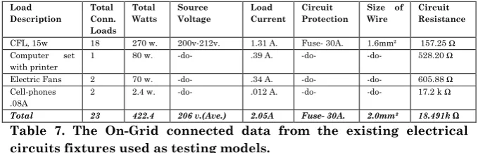
of the feeder wire used is small to efficiently carrying out the installed loads as shown in Table 7.
Table 7. The On-Grid connected data from the existing electrical circuits fixtures used as testing models.
After conducting all on-grid system tests and gathering all the necessary information and data, all electrical circuits and system to be used in performing the Off-Grid full-loading system were installed. All the vital contributing factors and related activities were taken before and during the conduct of testing and evaluations using the modified LH-PHEG System. The test and evaluation on the different parameters were based on the ambient temperature of 31⁰ C, the two pertinent variables, the equipment performances obtain in terms of mean optimum capacity and mean maximum power efficiency were obtained. As shown on Table 8, the researcher installed a lower ampacity of circuit protection device and changes the feeder wire into a larger diameter size that can efficiently hold the load capacity of the circuit.
Load Description Total Conn. Loads Total Watts Source Voltage Load Current Ckt. Protection
Size of Wire
Circuit Resistance
Compact Lamps, 15w
18 270w. 220 v. 1.23 A. CB- 10A. 2.0mm² 178.86 Ω
Computer set with printer
1 80 w. -do- .36 A. -do- -do- 611.11 Ω
Electric Fans 2 70 w. -do- .32 A. -do- -do- 687.5 Ω
Cell-phones .08A
2 2.4 w. -do- .011 A. -do- -do- 20 k Ω
Total 23 422.4 220v 1.921 A. CB- 20A. 3.5mm² 21.477 k Ω Load Description Total Conn. Loads Total Watts Source Voltage Load Current Circuit Protection
Size of Wire
Circuit Resistance
CFL, 15w 18 270 w. 200v-212v. 1.31 A. Fuse- 30A. 1.6mm² 157.25 Ω Computer set
with printer
1 80 w. -do- .39 A. -do- -do- 528.20 Ω
Electric Fans 2 70 w. -do- .34 A. -do- -do- 605.88 Ω Cell-phones
.08A
2 2.4 w. -do- .012 A. -do- -do- 17.2 k Ω
Table 8. Data gathered during the full-load test of the Off-Grid connected data from the existing electrical circuit fixtures as testing models using the LH-PHEG System.
Comparative Financial Aspects and other related ratios.
Based on the electrical bill with a cut-off date of May 28 - June 27, 2010 and bearing the Statement of Account No.3810455 from MSWD Office, a table of load analysis was established as shown on Table 9. Reflected are the description and other related information of the existing loads which are normally connected into the commercial/normal power lines of the Pampanga I Electric Cooperative Inc.(PELCO-I) without any intervention of the LH-PHEG System.
Table 9. The billed electrical loads and computations (May – June 2010) for MSWD which utilized the commercial power supplied by PELCO I.
Using the same MSWD office as the test model for the LH-PHEG System utilization, some changes and improvements were done on the existing fixtures and wiring installation. Selected electrical loads and circuits of the test model were transferred and connected to the LH-PHEG System for one month. Other electrical loads and circuits remained connected into the local power distributor source and both were utilized by the end-users. After one month, the total amount saved by the Government was seven hundred eighty one 78/100 pesos as shown in Table 10.
Load and Description Total Conn. Loads Total Watts
Total No. of Hours Used Per day
Total Kw./hr. Consumed (per day)
No. of days Utilized
Total Kw. used per Month
Amount of Power Consumed Fluorescent
Lamps, 20w 6 120 w. 7 hrs./day .840 Kw 30 days. 25.2 Kw. ₱170.30 Television set 1 75 w. ±11 hrs./day .803 Kw. -do- 24.09 Kw. ₱167.25 Electric Fans 2 150 w. ±20 hrs./day 3.0 Kw. -do- 90.00 Kw. ₱607.22 Refrigerator 1 120 w. 24 hrs./day 2.88 Kw. -do- 86.40 Kw. ₱580.49
Load and Description Total Conn. Loads Total Watts
Total No.
of Hours
Used Per day Total Kw./hr. Consumed (per day)
No. of
days Utilized
Total Kw. used per Month
Amount of Power Consumed
CFL @ 15 w.
ea. 6 90 w.
±7 hrs./day.
.630 Kw 30 days. 20.01
Kw.
₱127.76
Electric Fans (MSWD Office)
2 150
w.
±20
hrs./day 4.0 Kw. -do- 90 Kw. ₱605.36
Charging Outlet
2 5 w. ±18hrs./day .024 Kw. -do- 17.2 Kw. ₱48.66
Total --- 8 240w. --- 3.630Kw. 30 Days 108.90 ₱ 781.78
Table 10. Some electrical loads of MSWD office that were directly connected into the LH-PHEG system for 30 days and saved seven hundred eighty one 78/100 pesos.
Total Amount Saved = Total Bill Amount – Current Bill Amount
Total Amount Saved = PhP. 1,525.26 – PhP. 743.48 (as shown on Accounts No. 3848616)
Total Amount Saved = PhP. 781.78
Loads that were connected to the local power distributor Load and Description Total Conn. Loads Total Watts
Total No. of Hours Used Per day Total Kw./hr. Consumed (per day)
No. of days Utilized
Total Kw. used per Month
Amount of Power Consumed
Television set 1 73 w. ±11 hrs./day
.803 Kw. -do- 24.00 Kw. ₱162.19
Figure 14. The copy of the electrical bill for the month of June 28-July 27, 2010
Load and Description Total Conn. Loads Total Watts Total No. of Hours Used Per day Total Kw./hr. Consumed (per day)
No. of days Utilized Total Kw. used per Month
Cost of Power Consumed per Month
Cost of Power Consumed per Year
CFL @ 15 w. ea. (Tents and Park lights)
16 240 w. ±8 hrs./day.
1.92 Kw 30 days. 57.6Kw. ₱389.26 ₱4,671.12
Computer with printer @ 75 w. ea. (MSWD Office)
1 70 w. ±20 hrs./day
3.0 Kw. -do- 90 Kw. ₱608.22 ₱7,298.64
Cell-phone
Charging 2 5 w. ±2
hrs./day .01 Kw. -do- .30 Kw. ₱ 2.03 ₱ 24.36
Total --- 19 395w. --- 4.93 Kw. 30 days 147.9kw ₱ 999.51 ₱ 11,994.12 Table 12. Computed yearly savings of the Government on the electrical bill using the modified LH-PHEG system.
NOTE:
Data used for the above computation were as follows:
Source of the cost data: Pampanga I Electric Cooperative Inc.
1. Utilized alternator power output was only 80% of the 500 watts full capacity.
2. Voltage drop tolerance was ± 0.5 volts for every 15 meters distance of feeder wire.
3. The present base amount of ₱ 6.758 per kilowatt hour was used in the cost computations.
4. 30 days per month of continuous operation was the basis for one year period computation.
Socio-economic impact of the project
environmental stewardship and awareness among the residents especially the marginalized people of the community in particular.
Limitation of the Study
The LH-PHEGS is used to harness the potential hydro energy and applicable to small load / power utilization whose current rating is within the average capacity of the machine’s power output (e.g. 425 watts max. or 85% of the total rated power), 220 volts, 60 Hz., single phase (1ϕ) two wire system. The study focused on testing, evaluation and functions of the LH-PHEGS. The methods were primarily directed on evaluating the operations and performance of the devices and contribute in the efficient supply of electrical power. The evaluation was based on the researcher’s point of view as guided by the existing data stipulated on the manual of standard.
Summary and Conclusion
least 51.26% decrease on amount of beneficiary’s regular monthly electrical bill. Aside the monetary savings and system’s efficiency, the test and evaluation process guarantees its effectiveness due to continuous supply of electrical power (24/7) even at the peak of summer season. On the financial aspect, not only that it is positive to invest in this particular LH-PHEG System but also a higher internal rate of return is expected in this technology. With the utilization of the generated energy from the improved Pico-hydro system in the area, there was a great acceptance and appreciation to the technology.
Recommendation
The organizational programs must be established based on the needs assessment that will be done in this project program. With the active participation of non-government sectors or private individuals, the same corporate or single proprietorship form of organization can be adopted where the equipment and its facility will be considered as their investments.
However, the Government must intervene and support the project, a more comprehensive organization must be suggested for the project facility program where minimum fee shall be collected for battery charging and the amount shall be prorated with its size and type and other similar facility utilization for the maintenance of the LH-PHEG system.
Acknowledgement
Office (MSWDO), Community Environment and Natural Resources Office (CENRO) Park Protection Management Board (PPAMB) and 703 Infantry Brigade of the Armed Forces of the Philippines.
REFERENCES
Beale W. T. (2007) Solar Powered Free Cylinder Stirring Engine, Atlanta, Georgia USA.
Chutima P. (2005) Micro-Hydro Generators Designs and Experiments, Chulalongkorn, Bangkok, Thailand
DOE Annual Report Journal 2008, page 21. DOE Annual Report Journal 2009, page 45.
EC&M Magazine December 2009 edition, Vol. 104, page10 EPRI Research Manual 2009, Vol.45 pages 12-28.
Gapgo Energy Development. 2009.
http://www.gapgo.ca/hydro.html
Motor Maintenance Handbook, Joseph R. Kinsley, 5th Edition, pp.90-95.
Williamson S.J. et al., Low head pico hydro turbine selection using a multi-criteria analysis
http://www.sciencedirect.com/science/article/pii/S096014811200 3710?np=y