IJEDR1402163
International Journal of Engineering Development and Research (www.ijedr.org)2302
Effect of prime mover speed on power factor of Grid
Connected low capacity Induction Generator (GCIG)
1Mali Richa Pravinchandra, 2Prof. Bijal Mehta, 3Mihir D. Raval 1PG student, 2Assistant Professor, 3 Proprietor
1,2
Electrical Engineering Department, Sarvajanik College of Engineering & Technology Surat, India 3National Infotech, Surat, India
1[email protected], 2[email protected], 3[email protected]
________________________________________________________________________________________________________
Abstract - Ability of Induction Generator (IG) to convert mechanical power into electrical power over wide range of rotor speeds has given rise to an interest in study of Grid Connected Induction Generator (GCIG). Induction machine as an induction generator is used in different applications and becoming more popular because it reduces the system cost considerably compared to synchronous generator. But poor power factor is a major drawback of Grid Connected Induction Generator under varying prime mover speed. Hence, capacitor banks are connected across induction generator to fulfill the reactive power demand. It also helps to minimize losses and excitation process which assists the utility grid. This paper presents a simple model of grid connected low capacity induction machine operated from motoring mode to generating mode and effect of power factor with varying speed is discussed. The simulation model and results were obtained in MATLAB/SIMULINK software tool and a practical setup of 1 Hp GCIG is made with a suitable prime mover. Different readings were taken for speed and power factor compared with simulation results.
Index Terms— Induction Machine (IM), Grid Connected Induction Generator (GCIG), Power factor, Reactive power, MATLAB
I.INTRODUCTION
Nowadays, Induction Machine operated as an Induction generator is widely recognized, in order to conserve global resources. Induction generator plays an important role in electricity generation. It is used as either an isolated system or interconnected with power system network. Induction machine can be operated under two conditions namely, motoring mode and generating mode. Induction machine is operated from motoring mode to generating mode, giving negative slip. As speed during the generating mode is higher than synchronous speed, Induction Generator (IG) is also called as asynchronous generator. IG has relative advantageous features over DC Generator and Synchronous Generator, such as its simple construction, ease of maintenance, good transient performance, robustness, smaller size, absence of DC power supply for field excitation and low unit cost. [3-4]
Power factor is a priority to any electrical utility company, since if power factor is less than unity, company has to supply more current to the user for given amount of power use and so more line losses occur in the system. Power factor is defined as the phase difference between voltage and current. It can also define as the ratio of active power to the apparent power. Unlike Synchronous Generator, an IG needs reactive power for its excitation to convert the mechanical power into electrical power. Hence, this reactive power requirement must be supplied externally by capacitor bank, which is excellent source of reactive power. Thus it will improve the power factor of system if operating with reactive power consumption.
However, the major drawback of IG is that it is compulsory to provide external leading reactive power to generate electrical power. IG consumes some amount of reactive power under varying rotor speed, which results in poor power factor [4]. This paper deals with experiment with Induction Machine in generating mode, if it rotated at speed above synchronous speed and the generated power is fed back to the supply system. GCIG develop their excitation from the utility, but they require sufficient amount of capacitor bank to improve power factor under varying speed condition. The value of capacitor is not constant under varying speed of prime mover, but numbers of capacitors are needed to maintain power factor. In this paper, Grid connected low capacity Induction Generator with varying speed is simulated in MATLAB software tool and its effect on power factor been discussed with simple circuit model of IG.
II.INDUCTION GENERATOR
An IG is one type of AC electrical generator that uses the principle of Induction Machine. IGs are operated by mechanically turning their rotor in generating mode, giving negative slip. Regular Induction Machine is used as a Generator without any internal modification. An Induction Machine connected to an AC source of appropriate voltage and frequency can be operated either as a motor or as a generator. IG is rotated faster than synchronous speed and speed is decided by the supply frequency and the number of poles of the machine. For typical four pole operating on 50 Hz electrical utility grid, synchronous speed is 1500 RPM and same motor operate on 60 Hz electrical utility grid, synchronous speed is equal to 1800 RPM.
In motoring mode, stator flux rotation is higher than the rotor rotation. These initialize stator flux to induce rotor currents and it creates rotor flux with magnetic polarity opposite to stator. In this manner, rotor is dragged along behind stator flux, by some value equal to slip. In generating mode, a prime mover drives the rotor above the synchronous speed. Stator flux still induces currents in the rotor, but the opposing rotor flux is now cutting the stator coils, which produce active current in stator coils and now motor is operating as a generator.
IJEDR1402163
International Journal of Engineering Development and Research (www.ijedr.org)2303
generating mode. This means that machine needs reactive power and in varying speed condition of prime mover, IG suffered from the poor power factor. Low power factor is a problem in domestic area as well as in industry where numbers of motors are used so there is requirement to correct the power factor. Thus it require capacitor bank to fulfill the reactive power demand.The GCIG takes its excitation from the line and generates real power via slip control when driven above the synchronous speed. The operation is relatively simple as voltage and frequency are governed by the grid voltage and grid frequency respectively [4].
Figure 1 shows that a three-phase Induction Generator (IG) acting as a GCIG i.e. IG fed to the grid with capacitor bank. The induction generator requires an external source of reactive power. In figure 1 Qc indicates the reactive power of capacitor bank. This reactive power can be supplied either from the connected utility grid or from capacitors connected to the stator terminal of the IG. The capacitor bank is used for compensating the reactive power of the induction generator [1-4]. Pgrid and Pig are the active power of grid side and induction generator side and they are supplied from induction generator to grid. Qgrid and Qig are the reactive power of grid side and induction generator side and they absorbed by induction generator.
Fig. 1 Block diagram of IG feeding to the grid with exciting capacitor.
III.EQUIVALENT CIRCUIT ANALYSIS
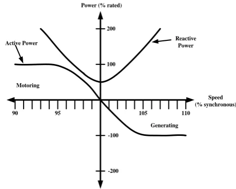
Figure 2 shows the relationship between active (real) power and reactive power as a function of a rotor speed at rated voltage for an induction machine operated as a motor and as a generator. This figure shows that the negative sign of the active power means that the active power supplied from induction generator to the grid in generating mode and positive sign of the active power absorbed by the induction machine i.e. motoring mode. The reactive power always absorbed by the induction machine like operating as motor and generator [2].
105 110
95 90
Power (% rated)
Speed (% synchronous)
Active Power Reactive Power
Motoring
Generating 200
100
-200 -100
Fig. 2 Motor and Generator Electrical Characteristic [2-3]
Motor: , (1)
So, motor slip ( ) is positive.
Generator: , (2)
So, generator slip ( ) is positive. Where, = synchronous speed
IJEDR1402163
International Journal of Engineering Development and Research (www.ijedr.org)2304
P = number of polesS = slip
Figure 3 shows the typical per phase equivalent circuit of a GCIG. In this circuit, Rs and Xs are stator resistances and stator reactance, Rr and Xr are rotor resistances and rotor reactance, Rm and Lm are magnetization resistance and inductance, respectively.
Vt
Rs
-RR/s
Rm Lm
XR
Xs
Is Im IR
Vag
Fig. 3 per phase equivalent circuit of the GCIG [4]
The input power,
(3)
The active power,
(4)
The reactive power,
(5)
Where,
V1 = stator voltage (V) I1 = stator current (A) ωr = rotor speed (rad/sec)
IV.SIMULATION AND DISCUSSIONS
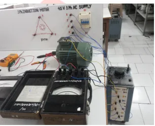
The simulation model shows the effect on power factor for varying speed of prime mover. This simulation is carried out in MATLAB software tool. Figure 4 show that the Grid connected low capacity Induction Generator without VAR compensation. In this simulation, 1Hp, 3phase, 415V, 50Hz, 1440rpm, star connected induction machine is being used. Equivalent circuit parameters of induction machine were found by using no-load test and blocked rotor test on physical 1 Hp motor [5-6]. Figure 5 show the practical setup of the no load test and blocked rotor test of induction machine and equivalent parameters are listed below:
Stator resistance Rs = 10.1 Ω, Stator reactance Xs = 15.81 Ω, Rotor resistance Rr' = 9.8546 Ω, Rotor reactance Xr' = 15.81 Ω and Mutual reactance Xm = 245.8954 Ω.
IJEDR1402163
International Journal of Engineering Development and Research (www.ijedr.org)2305
-K-rpm to rad/s
-K-rad/s_rpm XY- Graph v + -V A B C a b c Vabc Iabc Pf_ Pg Qg Subsystem
S peed and Torque Signal 1 Speed Variation signal rms signal rms w m A B C Induction machine i + -I Pf Q P I V speed Iabc Vabc N
A B C
415 V, 50 Hz
Fig. 4: Simulation of Grid connected Induction generator without capacitor bank
Fig. 5: No load and blocked rotor test for induction machine
V.SIMULATION RESULTS
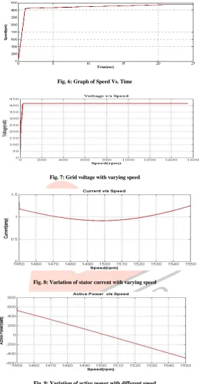
In Figure 4 induction Machine works in both motoring mode as well as generating mode at speed ranging between 1450 rpm to 1550 rpm. Figure 6 shows the speed variation with time. Figure 7 and figure 8 shows the grid voltage and stator current with different speed variation without compensation respectively. Figure 7 shows the grid voltage is constant throughout varying speed and current is changed as speed changes. The variation in active power for both motoring and generating mode is shown in figure 9.
IJEDR1402163
International Journal of Engineering Development and Research (www.ijedr.org)2306
Fig. 6: Graph of Speed Vs. TimeFig. 7: Grid voltage with varying speed
Fig. 8: Variation of stator current with varying speed
Fig. 9: Variation of active power with different speed
IJEDR1402163
International Journal of Engineering Development and Research (www.ijedr.org)2307
Fig. 11: Variation of power factor with speed of the induction machineVI.PRACTICAL SET UP OF INDUCTION GENERATOR AND RESULTS
The practical setup of IG is shown in figure 12. In motoring operation, rotor always turns slower than synchronous speed by amount known as slip. In generating operation, additional active current created in stator coils, but it will be back to the grid.
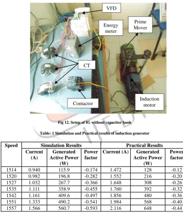
Fig 12. Setup of IG without capacitor bank
Table: 1 Simulation and Practical results of induction generator
Speed Simulation Results Practical Results
Current (A)
Generated Active Power
(W)
Power factor
Current (A) Generated
Active Power (W)
Power factor
1514 0.940 115.9 -0.174 1.472 128 -0.12
1520 0.982 196.8 -0.282 1.552 216 -0.20
1527 1.032 267.7 -0.366 1.648 308 -0.26
1535 1.111 358.9 -0.455 1.760 392 -0.32
1542 1.161 409.6 -0.497 1.856 480 -0.36
1551 1.333 490.2 -0.541 1.984 568 -0.40
1557 1.566 560.7 -0.593 2.116 648 -0.44
The purpose of this experiment is to study the behavior of low capacity motor when used as generator connected to utility grid and effect of varying speed on parameter of the system. As shown in figure 12, Variable Frequency Drive (VFD) and energy meter is used with IG. Different speed variation of prime mover is achieved by VFD and at same time related parameter like power factor, active power, average current are measured by energy meter. When speed above 1500 rpm was achieved, contactor is on than it started acting as a generator. Table 1 shows the practical results and simulation results of IG.
VFD
Energy meter
Contactor CT
IJEDR1402163
International Journal of Engineering Development and Research (www.ijedr.org)2308
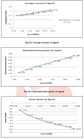
In above table, the practical result show that current is change with changing the speed of prime mover. Above 1500 rpm, active power is taken from prime mover and power factor is poor with increase in speed. Figure 13, 14 and 15 shows average current, generated active power and power factor is changing with varying the prime speed respectively.Fig 13: Average current v/s Speed
Fig 14: Generated active power v/s speed
Fig 15 Power factor v/s Speed
VII.CONCLUSION
IGs are used to produce useful power at wide range of rotor speeds. IGs are generally inexpensive and more reliable than synchronous generator and DC generator. They can be used for remote site and even the low capacity motor can work as generator. Simulation results and experiment results shows that the power factor is change with varying speed of prime mover speed and it is increasing but it is poor. Thus the capacitor bank is required to improve power factor. It also shows that, induction motor i.e. below synchronous speed consumes both active and reactive power and induction generator i.e. above synchronous supplies the active power to the grid and consumes the reactive power.
ACKNOWLEDGMENT
The authors sincerely thank to Electrical Engineering Department, SCET, Surat for providing continuously guidance and other facility to carry out this work.
REFERENCES
IJEDR1402163
International Journal of Engineering Development and Research (www.ijedr.org)2309
[2] B. Sawetsakulanond, P. Hothongkham and V. Kinnares, "Investigation on the performance between standard and high efficiency induction machines operating as grid connected induction generators," Sustainable Energy Technologies, 2008. ICSET 2008.IEEE International Conference on , vol., no., pp.848,853, 24-27 Nov. 2008.[3] V. Kinnares, B. Sawetsakulanond, “Characteristics Requirements of a Small Scale Squirrel Cage Induction Generator for Effective Electricity Generation from Wind Energy”, Energy Procedia 34(2013) 26-49.
[4] Li Wang; Ching-Chung Tsao, "Performance analyses of a three-phase induction generator connected to a utility grid," Power Engineering Society Winter Meeting, 2001. IEEE , vol.3, no., pp.1398,1402 vol.3, 2001
[5] Kumar, S.R.; Raja, P.; Selvan, M.P., "Virtual laboratory environment using MATLAB-GUI for teaching of induction generators," Dec-2012 Annual IEEE, vol., no., pp.676, 681.
![Fig. 3 per phase equivalent circuit of the GCIG [4]](https://thumb-us.123doks.com/thumbv2/123dok_us/8505169.1392648/3.595.37.453.154.454/fig-phase-equivalent-circuit-gcig.webp)