University of South Carolina
Scholar Commons
Theses and Dissertations
2015
Material Considerations for Development of 3D
Printed Bronchial and Tracheal Stents
Nidah M. Hussain
University of South Carolina
Follow this and additional works at:https://scholarcommons.sc.edu/etd
Part of theBiomedical Engineering and Bioengineering Commons
This Open Access Thesis is brought to you by Scholar Commons. It has been accepted for inclusion in Theses and Dissertations by an authorized administrator of Scholar Commons. For more information, please [email protected].
Recommended Citation
Material Considerations for Development of 3D Printed Bronchial and Tracheal Stents
by
Nidah M. Hussain
Bachelor of Science
University of South Carolina, 2013
Submitted in Partial Fulfillment of the Requirements
For the Degree of Master of Science in
Biomedical Engineering
College of Engineering and Computing
University of South Carolina
2015
Accepted By:
David Rocheleau, Director of Thesis
Damon Kolok, Reader
DEDICATION
To my late paternal grandfather, Ahmad Hussain, whom I lost to an illness this stent
may someday save others from, and to my maternal grandparents, Brig. Taimur Tareen and
Shameem Tareen, for inspiring me from an early age to pursue knowledge, be it science,
ACKNOWLEDGEMENTS
I would like to extend my thanks to all those hardworking individuals without whom
I would not have been able to achieve this degree. In particular, I would like to thank Dr.
Goodwin, from the University of South Carolina School of Medicine, for his helping me to
find a good direction to take my masters project in. My wonderful thesis director Dr.
Rocheleau has my gratitude for his continual guidance and sage advice throughout the course
of my project, and for giving me this opportunity to gain valuable experience in mechanical
engineering as well as my core biomedical training. My thanks to my fellow team members,
Zach Schwab for all his design and 3D printing work, and Caroline Horton for being my
liaison with the collagen team; without them this thesis would not have come together. I
extend my thanks to Dr. Tarbutton, also of the University of South Carolina, for taking a
chance with this project and cooperating with our lab to join biomaterial science and
three-dimensional printing to make these stent prototypes possible; also a thank you to Dr.
Tarbutton’s graduate student Taylor Corbett for his help and trouble-shooting with our 3D
printer. For my parents’ unending support and encouragement, I am thankful. Also, to
everyone else who helped in each of the many individual steps along the way, you all have
ABSTRACT
Tracheobronchial malacia is a commonly under-diagnosed condition that results
in difficulty breathing. The use of a tracheobronchial stent is the best course of treatment
for patients whose quality of life has deteriorated due to malacia; unfortunately stents
need replacing after issues with inflammation, migration, or eventual stent-breakdown
resulting in fistula formation.
The purpose of this thesis is to use three-dimensional (3D) printing technology to
improve on existing stents through designing and printing a bioresorbable/biodegradable
tracheobronchial stent that can treat tracheobronchial malacia. This was undertaken by
testing three biologically favorable materials, type I collagen, polycaprolactone (PCL),
and thermoplastic polyurethane (TPU), with desirable qualities that may result in
producing stents with idealized properties. These materials underwent print-compatibility
testing to determine whether, following a simple tubular stent geometry similar to the
Dumon silicone stent, these materials can be manufactured into a prototype stent via
innovative 3D printing methods. The resulting stents were mechanically tested and
compared to the industry standard Dumon silicone stent.
We demonstrated that PCL is fused deposition modeling (FDM)
printing-compatible, that TPU is potentially viable as a silicone alternative that is biologically
degradable, and that type I collagen can potentially be cured, using injection molding
TABLE OF CONTENTS
DEDICATION ... iii
ACKNOWLEDGEMENTS ... iv
ABSTRACT ... v
LIST OF FIGURES ... viii
CHAPTER 1:UNDERSTANDING THE PROBLEM MEDICALLY ... 1
1.1 History of Stents 1.2 Stents Today CHAPTER 2: THREE DIMENSIONAL PRINTING AS ASOLUTION:PROMISES AND SHORTCOMINGS ... 10
2.1 Tracheobronchial Stents and 3D Printing 2.2 Materials for Printable Stents 2.3 Stent Printing Process CHAPTER 3: STENT TESTING ... 21
3.1 FDA Non-Clinical Evaluation Requirements 3.2 Expandable or Self-expanding vs. Solid Stents CHAPTER 4: TYPE ICOLLAGEN STENT ANALYSIS ... 26
4.1 Designing and Manufacturing A Simple Tubular Collagen Stent 4.2 Collagen Stent Results CHAPTER 5: POLYCAPROLACTONE STENT ANALYSIS ... 31
5.2 Printing a Simple, Tubular PCL Stent
CHAPTER 6: THERMOPLASTIC POLYURETHANE STENT ANALYSIS ... 38
6.1 Printing a Simple, Tubular TPU Stent 6.2 Comparisons of All Materials CHAPTER 7: SUMMARY AND CONCLUSIONS ... 44
CHAPTER 8: FUTURE WORK ... 47
REFERENCES ... 48
LIST OF FIGURES
Figure 1.1. A Montgomery t-shaped tube stent ... 2
Figure 1.2. Silicone studded Dumon stent ... 3
Figure 1.3. A self-expanding silicone Polyflex mesh stent ... 5
Figure 1.4. Metal stents used today ... 6
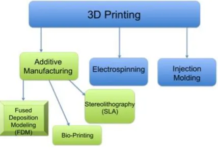
Figure 2.1. A sample of the different types of 3D printing and 3D manufacturing available today…. ... 10
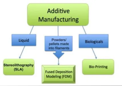
Figure 2.2. Examples of forms of additive manufacturing which are specialized for particular material types ... 13
Figure 3.1. Some stent characterization tests... 21
Figure 3.2. Balloon-expandable stent ...23
Figure 3.3. Schematic of a self-expanding stent and delivery catheter ...24
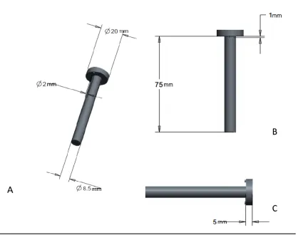
Figure 4.1. Rod designed using CAD software ... 26
Figure 4.2a. Shell of the mold, designed using CAD software... 27
Figure 4.2b. Body of the mold shell ... 28
Figure 4.3. Cap of the mold, designed in CAD ... 28
Figure 5.1. PCL filament extruder schematic ... 31
Figure 5.2. Extruder built for creating medical-grade PCL filament ...33
Figure 5.3. Medical-grade PCL filament tensile testing ...34
Figure 5.4. Comparison of medical-grade PCL filament vs. medical-grade silicone ...34
Figure 5.6. Compression testing set up ...36
Figure 5.7. Compression testing of PCL and Dumon stents ...37
Figure 6.1. Tensile testing experimental setup using the Tinius Olsen 5000 ...38
Figure 6.2. ‘Ninjaflex’ TPU filament tensile testing ...39
Figure 6.3. Compression testing of printed TPU stents vs. Dumon silicone stent ...40
Figure 6.4. Comparison of linearized sections of compression data from silicone and TPU stents ...40
Figure 6.5. Raw material comparison of PCL, TPU, and silicone ...41
C
HAPTER1.
U
NDERSTANDINGT
HEP
ROBLEMM
EDICALLY1.1 History of Stents
This research proposes the use of three-dimensional printing technology to create
implantable tracheobronchial stents. To examine this, a detailed overview of stent
technology over the course of history, as well as modern technology employed today,
will be presented.
Tracheobronchial malacia is a commonly under-diagnosed acquired condition in
adults, occurring within an estimated 10% of the population [1]. This condition is
characterized by tracheal cartilage flaccidity, a reduced anterior-posterior airway caliber,
and a widened posterior membranous tracheal wall; all of which result in a temporary
collapse of up to 50% or more of the trachea during eating, coughing, crying, and in
extreme cases, exhaling [2, 3, 4]. Type I and Type III tracheobronchial malacia are our
targets. Type I is congenital (birth defect) associated with esophageal atresia, or
trachoesophageal fistula formation. Type III is acquired through inflammatory conditions
like relapsing polychondritis (constant inflammation of cartilaginous structures of the
nose, ears, and laryngotracheobronchial tree in particular) or chronic tracheal infections,
as well as from prolonged intubation for medical reasons. Long-term treatment for this
condition involves the use of stents to improve the peripheral airway clearance and
Airway stents have been around and in use for close to 100 years. The earliest
among them appearing in 1915 through the work of Gustav Killian, known as the ‘Father
of Bronchoscopy’, and his students Brünings and Albrecht [5]. Many of the modern
airway stents began as endoprosthesis developed for implantation into the vascular
system. These implants were then adapted through minor modifications for central airway
usage. While in the early 1900s, the first airway stents were rubber, 1933 marked the use
of the first metal-based stent to treat laryngeal bony stenosis of a 2-year-old boy, by
Canfield and Norton [6]. Montgomery (Fig. 1.1) closely followed this in 1965 via the
creation of a silicone-rubber, T-shaped tube stent [7]. The year 1990 saw stent placement
officially become an acknowledged clinical, endoscopic treatment when Dumon
introduced a stent made of silicone, specialized for the trachea and bronchi [8]. Since
then, Dumon silicone stents are the most commonly implanted stent types in
tracheobronchial surgeries globally.
1.2 Stents Today
Today stents like the Dumon (Fig. 1.2) are employed for three major reasons:
primarily to reestablish airway patency, to provide support to weakened cartilage rings
when malacia occurs, or for providing a sealant when dealing with dehiscences and
fistulas in the esophagus [9]. Though not all prototypes were able to withstand the
passage of time, many types of stents still exist, and can be labeled as one of four chief
categories: metallic stents, covered metallic stents, polymer stents (like the Dumon), or
hybrids of metal combined with polymers such as silicone (like the Dynamic stent) [9].
Metal stents tend to be made of either stainless steel or Nitinol, a nickel and titanium
alloy, while polymer stents are almost primarily silicone [10]. Tissue response to a stent,
and the overall outcome of an endoscopic procedure, relies heavily on the material
composition of a stent and its resulting biomechanical properties [9], justifying the
documented use of the abovementioned materials historically.
Currently used stents are variable, depending on the nature of the particular
disease intended to be treated. Each of these stents uses materials foreign to the body,
although made biologically inert through modification. Much research of the following
stent types and designs, principally those developed or studied by Lutz Freitag, will be a
beneficial basis for future research at the University of South Carolina for a fresh,
innovative range of stent materials. These are to be based instead on bioresorbable or
biodegradable, polymeric materials better suited to integration and gradual breakdown in
the body, bringing the idealized stent closer to reality.
1.2.1 Polymer Stents
Among the stents of today, polymer stents like the aforementioned and popular
Dumon stent are most frequently used, and have become the ‘de facto gold standard’ of
the endoscopic world [8,11]. Composed of coated silicone, the shape resembles a hollow
tube with small rounded studs along the outside, while the interior surface is extremely
smooth. Partly due to their simplicity, Dumon stents are extremely versatile and come in
a range of sizes to allow for treatment of tracheal and bronchial stenosis from children
through adults. The stent can be repositioned and replaced with ease. These stents are
also prone to migration occasionally.
A polyester-mesh stent, very similar in design to the Dumon, is known as the
Polyflex stent (Fig. 1.3), and is even more adaptable than tube-shaped stents. This
flexibility is due to its circumferential length change when local compression is applied.
The addition of ‘tungsten spots’ at particular points in the mesh allow for visibility of the
stent in chest X-rays. The smoothness of the surface of the Polyflex stent makes it much
more prone to migration compared to other solid body tube stents. Correction of the
migration risk was attempted by the addition of spike-shaped silicone structures to the
exterior of the Polyflex and tested in animal models. This, however, was found to cause
severe granulation of local tissue [12].
The Montgomery stents have been modified slightly from the original 1965
design, having changed the composite material and the diameters of the T-tube; they are
primarily employed to treat tracheal stenosis starting from the vocal cords to further into
the trachea and bronchi. Stent migration is not possible with the Montgomery, as the use
of this stent necessitates a surgical tracheostomy in addition to the procedure. However,
this affects patient speech capability. Lymphatic flow and blood flow are not impaired in
any way, making this stent safest to employ for tracheal stenosis in this anatomical region.
1.2.2 Metal Stents
Metal stents like the Palmaz steel stent (Fig. 1.4) are mesh stents requiring
balloon expansion during deployment into the tracheobronchial region; these were
originally developed for use in the biliary duct and blood vessels [13], and have been
vivo, via manipulation with dilatation forceps or an angioplasty balloon. Epithelialization
(the migration of living cells into the implant to integrate the implant into the surrounding
tissue) occurs within weeks of implantation, but the stent is plastically inflexible as far as
the mechanical properties are considered. Although granulation formation is far less than
other metal stents, fluctuating pressure from coughing could permanently deform the
stent, requiring that serious caution be exercised when choosing this treatment route.
Implantation is limited to the region of the trachea or main stem bronchi.
Figure 1.4. Metal stents used today. Products of Boston Scientific. The Palmaz stent (4a), Wallstent (4b), and Ultraflex Strecker covered stent (4c), are all flexible mesh stents.
The Wallstent (Fig. 1.4) is also a woven metallic mesh, but is coated with a
polyurethane layer [14]. This design will not collapse when bent or compressed, making
throughout the trachea and less-uniform regions of the bronchial tree. Like many metallic
stents, the Wallstent shares a similar problem of causing granulation tissue formation.
As the Wallstent is completely compressed, lengthening occurs, while when partially
compressed the stent will shorten. The uncovered edges are slightly pointed, thus any
movement against the local mucosa will cause a tissue granulation response.
Another metal stent, the Ultraflex Strecker Stent (Fig 1.4), is better adapted to
kinked, irregularly shaped, or particularly smooth airways [9]. The wire filaments, which
are knitted to form this stent, are made of Nitinol and allow for epithelialization of the
stent such that functioning cilia can exist within the stent. The Ultraflex can be used to
treat a broad range of tracheobronchial stenosis, including those caused by tumors, and
can be used to seal airway fistulas to the pleural cavity, or to the esophagus. Although the
mesh allows for function of the mucociliary escalator within the airway, once again
granulation tissue formation is a problem to be considered with this stent, along with
tissue growth between the mesh.
A summary of each of these stent types, their material composition and subtypes
included, are found in Table 1.1. Additionally, benefits and shortcomings of each stent
Table 1.1. Summary of current major airways stent types and advantages or disadvantages [10].
1.2.3 Idealized Stent
As mentioned throughout, these existing materials do not satisfy all requirements
for an ideal stent, though many are functional and useful tools. Nearly all have reported
some form of complications, usually formation of tissue granulation (mainly in metal
stents), mucostatis due to necrosis or occlusion of the ciliary system within the airways,
and stent migration (particularly in Dumon, Noppen, and Polyflex polymer stents)
authors. These much desired and superlative properties require that stents are limited in
the amount of migration, tissue morbidity and mortality, additionally are easily removed
and placed, result in minimum granulation tissue formation, and maintain the potency of
the laminal tissue which the stents are placed in contact with [10,15] such that the natural
mucociliary escalator system in the airways is undamaged. In addition, an economical or
C
HAPTER2.
T
HREED
IMENSIONALP
RINTINGA
SA
S
OLUTION:
P
ROMISESA
NDS
HORTCOMINGS2.1 Tracheobronchial Stents and 3D Printing
Figure 2.1. A sample of the different types of 3D printing and 3D manufacturing available today. While the fasted growing of the categories is AM, and of that, FDM and Bio-printing, the ‘bio-printing’ process is still experimental and under development.
In this research, FDM (Fig. 2.1) printing is the primary method employed for
biodegradable/biocompatible stent design. Among its many benefits is the advantageous
feature of obtaining a device directly from the input 3D design within a matter of hours,
which makes it the most established and practical additive manufacturing (AM) method
Creation of a three-dimensional stent requires specialized equipment. While an
idealized stent needs to fit certain biological parameters and a set of engineering
parameters to make such a stent possible, economical parameters such as
cost-effectiveness are equally crucial. Depending on the material state, the stent is
three-dimensionally manufactured using a particular specialized process. For liquid-state
materials, such as liquefied metal alloys, stereolithography (SLA) is employed. For solid
materials in filament form, fused deposition modeling (FDM) is used. In this research we
focused on fused deposition modeling printing. Among its many benefits, FDM printing
allows manufacturing of stents that are customizable for individual patients; a design
aspect in much demand in the medical sector. With rapid advancements in this 3D
printing field married to medicine, pioneering the creation of the ideal stent can be that
much closer at hand.
2.1.1 Techniques of 3D Printing
Various methods of manufacturing stents are used today (Fig. 2.1), and all of
these methods are regarded as “three-dimensional” (3D) printing. However each method
has advantages and disadvantages. In this section, we describe the various 3D printing
methods. For tracheobronchial stents, the method of manufacture depends heavily on the
material.
Metallic stents are traditionally manufactured with subtractive manufacturing, in
which a laser cuts a piece of metal according to input parameters from a computer aided
design (CAD) type software to create a special netted wire mesh; 3D printing methods for
alloy powders are partially melted locally in order to conglomerate and form a solid
netted stent layer by layer [19-22]. Once cut, the stent is then prepared for coating using
techniques like chemical finishing and laser deburring. The stent can then be coated via
electroplating, or simply undergo electro-polishing. These processes are undertaken in
order to improve biocompatibility or to bestow biologically inert characteristics to the
stent [19, 20].
Metal injection molding is a method in which liquefied metal is forced through a
mold to create the final product geometry [21]. Assembly of wire filaments is a method in
which metal or metal alloys are made into filaments and assembled into a final mesh
design. These are alternative methods that can be employed when manufacturing a metal
stent, but depend on the metallic stent design in question [19].
Injection molding methods are primarily used for silicone polymer stent
manufacturing. Formation of the mold, however, must be completely personalized to the
patient, leading to great expense and time-consumption to achieve the final cured
geometry [23]. Because of this, many of the silicone stents available on the market today
are simply tubular structures, similar to the ‘gold standard’ Dumon stent (Fig. 1.2).
While customization of a mold is time consuming from a manufacturing
standpoint, customization of products is the ideal standard for reducing overall cost and
care-time in the health sector, particularly from the standpoint of the patient and of
healthcare companies. For this type of personalized manufacturing (that is, for stents
made of metal and silicone), additive manufacturing (AM) is the de facto method [24-27].
AM is the fastest growing printing method, particularly in the medical sector [18]; this is
AM can make use of three types of materials, using different specialized sub-techniques
for building with each material. As aforementioned, SLS manufacturing, a type of AM, is
used for solid materials, but specifically metal; for polymer resins in liquid form,
stereolithography (SLA) is preferred, although metal powders can also be combined with
liquid polymer to create a finished metal part [73]; both powders and pellets are made
into filaments for which fused deposition modeling (FDM) is the method of choice, both
of these also being AM subtypes.
2.2 Materials for Printable Stents
Figure 2.2. Examples of forms of additive manufacturing which are specialized for particular material types. Metals and metal-alloys are used in powder form and are processed using SLS printing; many polymers and ceramics come in powder form, although polymer resins are also available for SLA printing methods. Polymers are also found in filament form and available as spools. Biologicals involve
All material considerations for stents in this research were required to be either
bioresorbable, biodegradable, or biocompatible; therefore these key terms must be
clarified for the reader. The generally accepted definitions are as follows.
Materials that are ‘bioresorbable’ are completely eliminated from the body via
natural pathways like metabolizing or filtration of the byproducts, after bulk degradation
of that material [28, 29].
‘Biodegradable’ materials are defined as solid materials (including gels, grafts,
and implants), often of polymeric nature, that undergo macromolecular degradation in
vivo. This breakdown results in byproducts or fragments that do not necessarily exit the
body, but are removed from the site of action [28, 29].
While there is a broader definition for those materials termed ‘biocompatible’, the
FDA and European Society for Biomaterials (ESB) accepted definition of a medical
device that is biocompatible states the material should not elicit any undesirable systemic
or local effects, (such as toxicity or carcinogenic effects) [30, 31]. It is further stated that
the biocompatible material should elicit an ‘appropriate and beneficial’ cellular or tissue
response for that given situation.
Existing stents tend not to be biocompatible, but rather are biologically inert at
best, and employ a limited set of material types, namely silicone, metal-alloys such as
Nitinol, other metals such as Teflon [32, 33] or stainless steel [34], or a combination of
any of the aforementioned elements. In order to more closely achieve an idealized stent,
other materials with better biocompatibility are a necessity. Material science has grown in
leaps and bounds, producing many polymers with biomimicry capabilities, or substances
from the body via the usual rheological route. Elements native to the body have also been
aggressively studied and put to novel uses while maintaining the natural properties that
they are biologically specialized for.
In this research, we are focusing on FDM, which has certain material
requirements. Three types of materials were investigated for this research—ranging from
most natural and biodegradable, to least natural but biologically compatible. The first,
collagen type I, is a native, biological material; the second, middle-spectrum material,
polycaprolactone, is highly biocompatible and biodegradable but is also a
synthetic/soft-biopolymer; the third, thermoplastic polyurethane (TPU), is a promising biocompatible
polymer. These materials have yet to be tested for stenting, or yet to be proven as
manufacturable through the novel methods of FDM printing to create functional
tracheobronchial stents.
Collagen is the most natural of the materials we investigated; it is also the most
abundant in the mammalian body, making up 25-35% of the body’s total protein content
[35, 36]. This material is type I “fibrillar protein” collagen. On the nano-scale with its
highly organized alpha helices base, throughout till the micro-level with its intricately
structured fiber bundles, the architecture of collagen type I boasts high tensile strength
[37-40]. Viscoelastic properties of collagen, particularly as a hydrogel [41, 42], also favor
the use of type I collagen as a biomaterial for stent making. Additionally, cells easily
attach to and degrade collagen, allowing for reintegration of living tissue and production
of new collagen intercellularly in areas surrounding the implanted biomaterial [36].
Collagen is optimized for laying the structural foundations for a variety of tissues
suffering from symptoms of atresia or malacia. Fibrillar protein collagen is also very
versatile; capable of being reconstituted into hydrogels, macro-scale constructs such as
tissue grafts, microspheres for drug-delivery, or cell-seeded scaffolds, all of virtually any
shape and size [36].
While type I collagen holds much promise, few documented attempts have been
successfully made in creating a mostly- or fully-collagenous stent. Of all recorded papers,
the closest few, as of today, include an artificial tracheal collagen-coated mesh prosthesis
which was attempted as a basis for wound healing [33], with a similar type
collagen-coating attempted for a drug-eluting vascular stent [43]; an experimental carinal
reconstructive prosthesis conjugated with collagen coating was documented [44], and a
PLGA-collagen hybrid scaffold, reinforced with a copolymer stent and hydrogel, was
more recently attempted as a means of tracheal defect repair [45]. All these attempts had
relative success, underscoring the potential of collagen as a viable biomaterial for
tracheobronchial stent design.
With the aid of novel manufacturing methods such as 3D printing, in combination
with advancements in today’s technological equipment, this research could successfully
lay the groundwork for a type I collagen, resorbable tracheobronchial stent.
While materials, like type I collagen, which are inherently found in the body may
hold the best solution for compatibility and eventual reintegration of stents for long-term
recovery, materials that are highly biocompatible and/or bioresorbable are also very
promising. Among these is polycaprolactone (PCL), a semi-crystalline aliphatic
biopolymer that has biodegradable and biocompatible traits [46, 47, 48]. Unlike fibrillar
rate, undermines its effectiveness in allowing cell adhesion and eventual reintegration
into local tissue [49, 50, 51]. However, PCL can be broken down by microorganisms
outside the body quickly, while within the body it is slowly resorbed after the initial
hydrolysis-based degradation takes place [52]. Surface erosion, or degradation, occurs
when the surface-level polymer backbone is being cleaved hydrolytically, resulting in
external polymeric thinning while internally the molecular weight is basically unaffected
and will remain unchanged while degradation occurs [53]. With erosion of the polymer
occurring in this fashion, the lifetime of the breakdown process can easily be predicted,
and release rates for drug eluting implants and similar medical devices are readily
calculable [54]. This feature gives PCL the ‘bioresorbable’ property that has made it
popular for implants and tissue engineering scaffolds, sutures, wound dressings, and
dental devices, among many other medical uses [29].
Materials that are deemed bioresorbable tend to double as being biocompatible,
given that the body’s tissues tolerate that same material well [55]. Being both
biocompatible and bioresorbable, PCL has ideal rheological properties and can easily exit
the body harmlessly, while its viscoelastic properties mean production and manipulation
of the polymer are easy, and degradation time can be specifically tailored to fit the
particular, necessary device lifetime [29, 54]. Because of its many favorable traits,
attempts have been made to use PCL to fabricate a tracheobronchial stent for airway
remodeling in the past [56, 57]. None of these attempts thus far employed novel 3D
printing methods, or have proven that this material is 3D printing-compatible.
The third material studied in this research, TPU, is biologically compatible [58]
of this thermoplastic polyurethane (TPU) compound would make the printing of a great
variety of personalized stents easily plausible. TPU has high strain recovery and is highly
tunable or “smart”, meaning it will return to its initial shape; it is light weight and easy to
process, making it ideal for 3D printing, in addition to being low cost, which makes it
economical [59, 60].
FDM methods like 3D printing require filamentous material input; the heat-based
extrusion process has the potential to alter material properties, particularly of
thermoplastic or thermally sensitive substances like TPU. Extruded TPU under repeat
cyclic-loading and unloading, which are conditions an implanted stent is likely to
experience during reflexive events such as coughing, eventually exhibit inelastic effects
such as residual strain, hysteresis loss, and stress-softening; this is usually under maximal
strain, however [61]. Given thermoplastic polymers have high resilience and low stiffness,
while handling friction well [62], and because these polymers have shown higher strain
capability and strain recovery values when copolymeric sequences are more randomly
distributed [63], the aforementioned problem of inelastic/plastic deformation can be
worked around.
An additional concern for thermoplastic composites in general includes the
plasticizing effect which moisture absorption has on the material [64, 65]. Medical grade
thermoplastic polyurethanes have been used in completely moist of fully humid
environments such as the mouth or intravenously, either for orthodontic purposes or
vascular grafts, respectively [63, 66]. Based on this information, it can be deduced that if
TPU can successfully be cross-linked in a manner that creates material insolubility, it is
material has been used in combination with 3D printing in the past, there is no
documented use of TPU in tracheobronchial stent design as of today.
2.3 Stent Printing Process
For this research, FDM printing is the primary method employed for
biodegradable/biocompatible stent design, given the advantageous feature of obtaining a
device directly from the input 3D design, which makes it the most-established AM
method in the medical field today [17, 18]. FDM traditionally only makes use of the
filament-form of any material; that substance is then directly deposited using a system of
layers building upon earlier layers, until the final device is formed. Silicone stents have
been manufacturing using a very similar technique, but often must be injection molded
and require a lengthy curing process afterward [67, 68, 69]. TPU polymers are flexible
and share many mechanical properties which are similar to the traditionally used silicone,
but TPUs are designed to be more 3D printing friendly, while polymers like PCL, or
biological materials like type I collagen, have not been successfully printed using FDM
technology; attempting this pioneering process with these materials is also part of the
focus of this research.
As newly available biological materials that increasingly emulate natural tissues
are becoming widely accepted for use in the medical field, these materials show great
promise for the future of endoprosthesis [70]. In combination with an innovative stent
design and manufacturing technique, the creation of a prototype stent not made of
silicone or metal, but with materials of ideal mechanical properties like thermoplastic
57, 71], as well as a biomaterial like fibrillar protein collagen with potential for resorption
into the airway [36], would provide a novel, unique edge to research at the University of
C
HAPTER3.
S
TENTT
ESTING3.1 FDA Non-Clinical Evaluation Requirements
The FDA requires certain mechanical properties be quantified for non-clinical
evaluation of stents [72]. However, no widely accepted, industry-standard protocol exists
for obtaining these properties for airway stents. The FDA publishes specific guidelines
for vascular stents that can be adapted for airway stents. For this research we performed
certain basic mechanical analyses, such as tensile testing and compression testing, to
characterize both the raw materials for each of the stents proposed, as well as the
post-processed form (stent) itself. The significance of these properties to airway stent
performance will be described in this section.
After a stent is designed, documented testing is necessary in order to demonstrate
safety and proper functionality in accordance with FDA guidelines. This allows
physicians to determine under what conditions, and where, the best stent placement
should be.
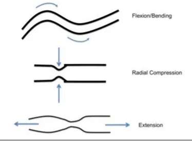
While no particular FDA protocols are given for airway stents, there are certain
mandatory, non-clinical engineering data or properties that the FDA requires be
quantified. Among these requirements are forms of uniaxial compression or elongation
(extension) testing (Fig. 3.1), to characterize a stent’s performance under short and
long-term external loading/unloading [72]. Stent stress and strain responses delong-termine stent
Figure 3.1. Some stent characterization tests. Angles of forces applied to stents during various standard tests that will determine maximal stress or strain the stent can withstand.
yield strength), and its maximal deformation limit, (known as the ultimate tensile strength
point) for each stent will directly correlate with its clinical performance.
For certain stent designs, for example mesh stents and expanding stents, the FDA
also requires particular radial strength and radial stiffness testing unique to each stent’s
specific dimensions. Material composition also requires certain additional tests for yield
strength, elastic (Young’s) modulus, and endurance limit, among others [72]. Again,
these quantify the strength of the stent.
3.2 Expandable or Self-expanding vs. Solid Stents
The stents manufactured in this research are all termed ‘solid’ stents, having the
delivered using rigid bronchoscopy, and are already in the final conformation state they
have while deployed within the trachea or bronchi; therefore these are not considered
‘expandable’ stents.
In contrast, an expandable stent changes shape after insertion. Expandable stents
are further divided into either balloon-expandable or self-expanding stents.
Balloon-expandable stents are usually delivered via the flexible bronchoscopy method (this
procedure does not require general anesthesia), and as the name implies, such stents are
maneuvered into place prior to being expanded to their final conformation. Stents of this
type are usually tightly wound over a flexible catheter tipped with a small balloon (Fig.
3.2), which is used to guide the stent into place, then inflated by the physician in order to
deliver the stent. The balloon is deflated once the stent is placed, and the catheter itself is
removed.
Figure 3.2. Balloon-expandable stent. Mounted on a flexible catheter and delivered to the
Self-expanding stents are ‘spring loaded’ into special catheters. Once the catheter
is correctly positioned, the stent is released from the device and immediately expands to
achieve its final conformation (Fig. 3.3).
Figure 3.3. Schematic of a self-expanding stent and delivery catheter. In 3.3A, both the loading of the stent into, and the delivery out of, the instrument is facilitated via a netted sleeve. Illustrated in 3.3B, the stent is being compressed as it is loaded into the netted sleeve such that it may deploy and expand to appropriate geometry when delivered into the airway.
Additional properties to report for balloon-expanding and self-expanding stents
are required by the FDA to determine the recoil and radial outward force exerted by the
stent on the surrounding tissue. Forces that are too great risk a possibility of damaging
tissue local to the stent. Weak expansion forces may result in a partially deployed stent,
which in turn could occlude the area in which the stent was placed, or cause the stent to
migrate out of the target location. Foreshortening, or the potential change in stent
Testing that exceeds FDA requirements has been undertaken in past research to
study stent migration and behavior. Such testing includes stent behavior in the tracheal
region under conditions of coughing, in vivo studies, or development and modeling of
stent behavior using complex simulation software [75-77]. Such testing is beyond the
C
HAPTER4.
T
YPEI
C
OLLAGENS
TENTA
NALYSIS4.1 Designing and Manufacturing A Simple Tubular Collagen Stent
One of the goals of this research was to create a simple, smooth-walled stent
similar to a basic Dumon silicone tube stent. We created three tubular collagen stent
prototypes with the injection-molding 3D printing process. Such stents allow for
comparison of the material properties of each the 3D printed stents to the Dumon silicone
stent that holds de facto go-to status for non-metallic stents.
While direct FDM printing of gel-like collagen would be most advantageous (see
Chapter 2), such is not yet possible. Our procedure was to use SLA methods to print a
mold (Figures 4.1-4.3) from an acrylonitrile butadiene styrene (ABS)-like material. This
mold was subsequently used for the 3D injection molding of the collagen stent. Injection
molding was most conducive to working with raw type I fibrillar collagen. A team
member, using a CAD package, designed the individual parts of the 3D printed mold.
The collagen was obtained and prepared from the hide of an 18-month-old bovine
Figure 4.1. Rod designed using CAD software. It is placed in the center of the mold, allowing for construction of patent inner lumen of tube. Various angles are shown here along with respective measurements.
Because collagen was demonstrated to be more conducive to the injection
molding 3D printing method than to the FDM method, simple collagen tubes were
manufactured via injection molding using standardized methods, and were mechanically
tested (Appendix A).
The collagen tubes were already primarily cross-linked via pH crosslinking, in
order to set each tube in its respective mold. Next, the tubes were further polymerized
using UV cross-linked via a UV Stratalinker 2400 introducing 0.12 millivolts of UV light
at a wavelength of 166.7 nm in each burst. Polymerization was done to further increase
Figure 4.2a. Shell of the mold, designed using CAD software. This design was intended to determine the outer diameter of the tube stent. The pinpoint holes in the body of the shell are in the micrometer range; these are intended to release pressure when collagen is injected in, as the formation of air bubbles compromises stent integrity.
The detailed collagen preparation and concentration procedure is included in
Appendix A. Collagen concentration was determined by a weight percent (wt%)
calculation:
𝑤𝑡% 𝑐𝑜𝑙𝑙𝑎𝑔𝑒𝑛 = 𝐷𝑟𝑦 𝐶𝑜𝑙𝑙𝑎𝑔𝑒𝑛𝑊𝑒𝑡 𝐶𝑜𝑙𝑙𝑎𝑔𝑒𝑛 𝑥 100% (Eq. 1)
The experimental range of wt% used started with the lowest concentration of 0.5 wt%,
the next being 0.77 wt%, another concentration at 0.83 wt%, and the highest
Figure 4.2b. Body of the mold shell. Again, the pinpoint holes of 1.25μm diameter intended to release pressure from injecting fibrillar type I collagen. The 2.01mm indent is where the cap will snap securely into place on either end of the mold shell.
4.2 Collagen Stent Results
The objective of this research was to use 3D printing methods to manufacture a
simple cylindrical tube-like collagen stent and test its mechanical properties. These
stress-strain properties were to then be compared to the average total radial pressure force
(35kPa) that a tracheomalacial patient’s trachea will experience due to flaccid smooth
muscle collapse during exhalation. The collagen tubes had a tendency to shrink slightly
after removal from the molds and storage in HEPES buffer solution.
Collagen tubes having varying levels of polymerization (0X, 10X, 40X, and 80X)
were cut into sections of 2.5mm thick, 7mm diameter discs. Compression testing of the
resulting collagen tubes was undertaken using a rheometer. Individual Young’s moduli
were calculated, along with stress-strain data, and were plotted (Appendix A).
Those collagen discs that were only pH cross-linked enough to maintain their
tubular conformation, yet did not experience UV-polymerization (0X cross-linking), were
expectedly extremely weak. These discs would deform irreversibly at around 8,500Pa of
compressive force. However, the average compressive force experienced by the trachea
of a tracheomalacial patient is 35kPa (Appendix A). No significant differences in
compressive strength were demonstrated between UV polymerized (10X, 40X, 80X) and
un-polymerized (0X) collagen discs of the same wt% collagen. Collagen discs at 3 wt%
of all cross-linking levels displayed greater compressive strength compared to those of
C
HAPTER5.
P
OLYCAPROLACTONES
TENTA
NALYSIS5.1 Preparing a PCL Filament
Few pure polycaprolactone stents have been manufactured in past studies,
particularly for use in the airway; among these few publications, medical grade PCL has
primarily been used with other 3D printing methods such as liquid-based SLA or
injection molding [56, 57, 74]. Prior to this research, medical grade PCL has not been
demonstrated to have been processed into a filament, or, by extension, used in
combination with FDM printing.
In accordance with the objectives of this research, the PCL filament was created
via the use of an extruder built for this purpose, its optimal FDM printing conditions were
determined, and a tubular PCL stent of similar geometry to the Dumon silicone stent was
printed. This was then mechanically tested to characterize and compare the PCL stent to
the industry standard Dumon silicone stent.
In order to determine if PCL was capable of being FDM printed, and what the
temperature specifications of printing were, 12oz of hobbyist quality ‘Instamorph
moldable plastic’ polycaprolactone pellets were purchased from Instamorph [78]. Using a
DSM Xplore Micro 5cc Twin Screw Compounder, the Instamorph polycaprolactone
pellets were extruded into a 3m long, 1.90mm diameter filament at 90oC, 1.7kN, and
On a Solidoodle FDM printer, the Instamorph PCL filament was printed at
various temperatures, beginning with its usual melting point at approximately 60oC,
until an optimal temperature and maximal speed of printing were determined. Based
on this data, we determined that polycaprolactone was FDM printing compatible.
Similarly, 500g of medical-grade polycaprolactone (Mn 80,000) was ordered
from Sigma-Aldrich [79] and was processed into a filament using a DSM Xplore
Micro 5cc Twin Screw Compounder with similar parameters as above. However, a
higher temperature of 93-95oC was required to extrude pellets into the final 1.6mm
diameter filament form.
As the Twin Screw Compounder was not optimized for extruding material
having the particular viscosity of medical-grade PCL, the Compounder began to singe
the PCL filament. Burning results in alterations of the properties of the PCL filaments.
In order to prevent introduction of error, an extruder was specially built to process the
medical-grade PCL filament. Filament was extruded at 60-65oC.
Figure 5.2. Extruder built for manufacturing medical-grade PCL filament. Attached is a thermocouple providing heat for the extrusion process. A team member designed the extruder. The stainless steel extruder body is 13.45cm long with a 33.30mm outer diameter. The opening of the 14.85mm diameter brass tip is 1.58mm diameter. Pellets are poured into 21.55mm inner diameter Teflon body, then the plunger is pushed in using a 12-ton hydraulic shop press.
Tensile testing of extruded medical-grade PCL filaments was undertaken to
characterize material properties compared to the medical-grade silicone of the Dumon
stent. On a Tinius Olsen 5000, a 1.44mm diameter PCL filament was tested to
determine material mechanical properties of stress and strain. The Tinius Olsen 5000
was hooked up to a data acquisitioning device (DAQ) reading voltage output for
displacement and force into LabView SignalExpress software. Exported data was
Figure 5.3. Medical-grade PCL filament tensile testing. Average of all trials reported above. PCL filament began necking immediately, but was able to continue to stretch without further decrease in filament diameter for a maximal 12 inches, prior to concluding the test.
Figure 5.4. Comparison of medical-grade PCL filament vs. medical-grade silicone. A strip of silicone 2 inches long and 5mm in diameter was compared to the 2 inch stretch of 1.44mm diameter PCL. Average trials of both being compared, results suggest that PCL can handle a greater force load compared to silicone for a longer period of time.
0 5 10 15 20 25 30
-0.01 0 0.01 0.02 0.03 0.04 0.05 0.06 0.07 0.08 0.09
Str e ss (N ) Strain (%) 0 5 10 15 20 25 30
-0.02 0 0.02 0.04 0.06 0.08 0.1 0.12 0.14
Str e ss (N ) Strain (%) PCL Silicone
EPCL = 9.90 MPa
EPCL = 9.90 MPa
5.2 Printing a Simple, Tubular PCL Stent
PCL stents were printed using a Solidoodle FDM printer. The basic schematic
is as follows (Fig. 5.2). Filament is fed between the driver and idler gear. Using
torque, the gears then feed the filament further into the nozzle where it is then heated;
the semi-solid material then exits the nozzle tip to print the final product onto a
temperature-controlled stage that can be raised or lowered.
Figure 5.5. Schematic of an FDM printer. The driver motor turns the toothed primary or ‘driver’ gear, while the secondary smooth ‘idler’ gear aids in feeding filament into the nozzle. At the end of the nozzle is the heating element that melts the filament, allowing it to be extruded through the tip of the print head and used to print a stent.
printer, printability of Instamorph PCL as a biomaterial was tested. At 70oC the
filament was extruded consistently at 5 minute printing intervals, supporting that PCL
is viable 3D print-capable material.
Similarly, using a Solidoodle FDM printer, higher quality medical-grade PCL
filament was printed at 200oC, generating a 30mm diameter ring. Parameters were
further adjusted and a prototype simple tubular stent of 7.85 x 103 mm3 material
volume was printed in a vertical orientation.
Printed stents were then compression tested using a Bose Electroforce 3200
load frame system (Fig. 5.6), applying 1N of force across the full length of the stent,
at a crosshead speed of 0.001m/sec. Compression testing methods used in this
research are similar to the previous stent-testing procedures used by Saito et al., 2002
and Liu et al., 2011. The medical-grade PCL stents were compared to industry
standard Dumon silicone stents (Fig. 5.7).
Figure 5.7. Compression testing of PCL and Dumon stents. The PCL stent segment that was compression tested was then normalized along the final length of the final intended stent geometry of both the TPU and Dumon silicone stents. However, the PCL compression testing was not successful.
The final FDM printed PCL stent tested was not the exact length of the testing
standard Dumon stent. Therefore, a smaller segment of the PCL stent was
compression tested following the above-mentioned procedure for compression testing.
The resulting data for the stent segment was then normalized along the final length of
a PCL stent that would be geometrically identical to the Dumon stent in length. This
normalized data was then compared to silicone compression results.
0 0.01 0.02 0.03 0.04 0.05 0.06 0.07 0.08 0.09
0 0.5 1 1.5 2 2.5 3 3.5
Str e ss (N ) Strain (%) Silicone
C
HAPTER6.
T
HERMOPLASTICP
OLYURETHANES
TENTA
NALYSIS6.1 Printing a Simple, Tubular TPU Stent
A spool of colorless, 1.30mm diameter thermoplastic polyurethane material
was purchased from Fenner Drives (trade name ‘Ninjaflex’) [80]. The material was
already in filament form.
Tensile testing of a 1.30mm diameter TPU filament was undertaken using a
Tinius Olsen 5000 tensile tester. Force recording was set to 5% force-recording range
of the total 5000lb load cell, and extension-recording range was set to a maximum of
25 inches (Fig. 6.1). All data was collected via a DAQ device using LabView
SignalExpress software, and exported for processing to Excel (Fig. 6.2).
Figure 6.2. ‘Ninjaflex’ TPU filament tensile testing. Average of all trials reported above. TPU filament was able to elastically recover after each test, returning to its same morphology after undergoing maximal stretching of 10 inches, prior to slipping out of tensile clamps.
On a Solidoodle FDM 3D printer, printability of Ninjaflex thermoplastic
polyurethane as a biomaterial was tested. At 205oC the filament was extruded
consistently onto a 60oC heated bed. The standard print speed of 30mm/s was
maintained. The resulting proto-stent measured 18.61mm diameter x 3mm thick x
30mm length. Evidence supports that TPU is viable 3D print-capable material for the
design of implantable airway stents.
Resulting TPU stents were then compression tested using a Bose Electroforce
3200 load frame system (Fig. 5.6), applying 1N of force across the full length of the
stent, at a crosshead speed of 0.001m/sec. Stress-strain curves as well as percent
displacement were determined (Figures 6.3 and 6.4). Compression testing methods
0 5 10 15 20 25 30
0 0.5 1 1.5 2 2.5 3 3.5
Str
e
ss (N
)
Strain (%)
used in this research are in accordance with previous stent-testing procedures used by
Saito et al., 2002 and Liu et al., 2011.
Figure 6.3. Compression testing of printed TPU stents vs. Dumon silicone stent. The smaller diameter TPU stent’s radial stiffness ran nearly identical to the silicone stent of the same geometry.
Figure 6.4. Comparison of linearized sections of compression data from silicone and TPU stents. This graph more obviously displays the smaller diameter TPU stent’s radial stiffness ran nearly identical to the silicone stent of the same geometry.
0 50 100 150 200 250 300 350 400 450
0 0.5 1 1.5 2 2.5 3 3.5
Str
e
ss (Pa)
Strain rate (%)
TPU Small Stent
Silicone Stent 0 0.05 0.1 0.15 0.2 0.25 0.3 0.35 0.4
0 10 20 30 40 50
Str
e
ss (N
)
Strain (%)
TPU Small Stent
Silicone Stent
ESi = 20.48 MPa
All polymer stent tensile (Fig. 6.5) and compression (Fig. 6.6) testing results were
compared and plotted. The elastic moduli (E) were also calculated and compared in
Table 6.1. It was noted that TPU was capable of further displacement during tensile
testing, however, extension beyond the 12in displacement maximum was disregarded
as being beyond the scope of research parameters.
Figure 6.5. Raw material comparison of PCL, TPU, and silicone. Each filament’s average is plotted
above. While PCL underwent immediate necking, then maintained load bearing steadily, TPU continued to elastically deform. Silicone immediately reached maximal load bearing ability, then maintained its load for a brief period, prior to slipping from the testing clamps.
0 5 10 15 20 25 30
-0.02 0 0.02 0.04 0.06 0.08 0.1 0.12 0.14
Str e ss (N ) Strain (%) PCL average Silicone average TPU average
EPCL = 13.94 MPa
ESi = 4.14 MPa
Figure 6.6. Stent compression comparison. PCL, while having a higher elastic modulus than Silicone or TPU, lacked the stiffness of the other stent materials of identical size. PCL compression test failure meant the data was not included.
Testing parameters and results are supported by previously published results
for elastic moduli of silicone, PCL, and TPU materials. The general acceptable range
for silicone modulus is between 2-6MPa [82], although up to 10-15MPa is not
uncommon for medical grade silicone, particularly for airway stents [19, 83]. The
general elastic modulus for medical grade PCL (Mn 80,000) is approximately
14-16.9MPa, although changes in polymer chain microstructure can affect this [84]. For
TPU, the modulus range begins at 10MPa and goes up to approximately 5GPa,
depending on the specific purpose for TPU [85].
Elastic modulus values for a standard tubular stent made from each respective
material differ from the raw material values. Unfortunately, the specific elastic
0 0.5 1 1.5 2 2.5 3 3.5 4 4.5
0 0.5 1 1.5 2 2.5 3 3.5
Str e ss (N ) Strain (%) Silicone TPU
ESi = 20.48 MPa
modulus for the Dumon silicone stent was not available for comparison to measured
values during compression testing, due to the proprietary nature of the product
specifications. While for medical applications acceptable silicone elastic moduli vary
anywhere from 3-30MPa [86], and stent elastic moduli must be at least 15MPa for
pulmonoscopic insertion [87], the silicone stent tested had an average elastic modulus
of 20.48MPa. A PCL stent modulus value can be as high as 352MPa depending on
processing method [88, 89], though no standardized value for a pure PCL tube stent
has yet been published. Compression results were unsuccessful so the elastic modulus
was not determined. For the TPU stent, an elastic modulus of 32.28MPa resulted.
Table 6.1. Comparison of material elastic moduli measured, and respective industry standards.
Material
Elastic Modulus (MPa)
Silicone Strip 4.14
Silicone stent (Dumon) 20.48*
PCL filament 13.94
PCL stent --
TPU filament 19.91
TPU stent 32.28
where (*) represents unavailable data due to intellectual property.
Again, the geometry of both TPU and PCL stents were identical to the Dumon silicone
stent tested, with the exception that the shorter PCL stent segment was tested and data
normalized along final stent length to match the Dumon and TPU stents.
Elastic modulus data for raw material and each FDM printed stent are verified
by existing publications [84-86, 88, 89], suggesting values for compression and tensile
C
HAPTER7.
S
UMMARYA
NDC
ONCLUSIONSTracheomalacia, in the forms of esophageal atresia or trachoesophageal fistula
formation, can be treated with stenting. Migration, inflammation and granulation tissue
and fistula formation commonly occur with long-term stenting, due mostly to the limited
material types of existing stents.
Stenting has improved enormously since the 1900s when it first began. There is
still much room to grow, and material science has since advanced further. From among
the many advanced materials available today, type I fibrillar collagen, polycaprolactone
polymer, and thermoplastic polyurethane polymer were explored for this research. The
goals of this research were to demonstrate 3D-printing capability of each polymer
explored, to mechanically test the resulting printed stent, and to compare these stent
results to the current industry standard: silicone stents.
This research identified the potential of using FDM printing for quick, on-site
manufacturing of simple stents. This indicates FDM is indeed a viable 3D printing
method for polymer stent manufacturing in the future, and should be further explored.
The FDM printability-analysis demonstrated medical-grade PCL can be confirmed to
print under carefully maintained conditions of 120-130oC, and a rate of 8mm/sec. FDM
printability of TPU has been reaffirmed, and potential applications as a stent were
explored mechanically. TPU results were similar to medical-grade silicone polymer.
This research contributed to furthering the advancement of stent development for
stents can be manufactured. Stent manufacturing was undertaken using FDM printing
methods. Each of the polymer materials was compared to the industry standard silicone
polymer. Testing results suggest that biocompatible/bioresorbable PCL, and
biocompatible/biodegradable TPU are able to handle equal or greater compressive loads
than silicone before plastic deformation occurs. Collagen proto-stents that were
manufactured were of 3wt% or less collagen concentration, and were not able to achieve
the same load-bearing ability equal to the polymers tested.
Linear regions of stent stress-strain curves for each material were plotted and
compared. Results suggest very similar behavior between TPU-based and silicone-based
stents. Pure PCL showed greater elasticity than silicone, and thus was not as stiff. While
the PCL compression testing was unsuccessful, the segment tested lacked equal or greater
stiffness compared to silicone or TPU. Further testing, printing of a full-length PCL stent,
and continuous tweaking of printing parameters for PCL may result in a PCL stent with
varied elasticity, as well as a stiffer PCL stent.
This research identified the potential of using type I fibrillar collagen for stenting.
Tubes were formed through injection molding 3D printing methods, yet higher collagen
wt% levels and even greater levels of UV polymerized cross-linking should be explored.
Analysis of collagen proto-stents demonstrated collagen tube compression loading
maxima (Appendix A). Results suggest the tubes need to be made using a greater
concentration of collagen to withstand the average 35kPa forces experienced by the
trachea in a case of tracheomalacia. With the current collagen concentration method, it is
difficult to concentrate beyond 3wt%; revisions to the protocol could be undertaken to
Overall, these results are very promising. Through this research, material
printability of type I fibrillar collagen, PCL, and TPU were determined, along with tensile
and compressive strengths of stents manufactured in comparison to silicone. Results
suggest TPU and PCL show promise as alternatives to silicone polymer stents as an
C
HAPTER8.
F
UTUREW
ORKWhile this research presented an overview of the process of creating a stent via
AM methods of FDM printing, there are still points which need addressing. First, the
stents were all manufactured in the form of a simple cylindrical tube much like the
Dumon stent. For our purposes this simple geometry was justified, however, more
complicated stent geometries such as mesh-stents are where future research could be
directed.
Continuing to adjust parameters for collagen tube stent stiffness to attempt to
identify ideal material UV-polymerization levels should not be excluded from future
research. As well, future studies should include additional measurements with a larger
sample size of collagen tube stents over a greater range of crosslinking levels. PCL
printing parameters can also, through further exploration, possibly offer stents with
differing elasticity such that a slightly stiffer PCL stent, at the full of a Dumon stent, can
be printed.
The present research was limited to printing of basic stent geometries and
mechanically testing each stent for characterization of stent behavior, similar to tests
undertaken in past research. This was done under the assumption that the materials were
likely biocompatible when post-processed into stents. While justified for the scope of this
research, integration of in vitro testing of processed materials is required to support the
R
EFERENCES[1] Ikeda, S., Hanawa, T., et al., “Diagnosis, incidence, clinicopathology and surgical treatment
of acquired tracheobronchomalacia.” Nihon Kyobu Shikkan Gakkai Zasshi. 1992. 30(6):1028-35
[2] Beasley SW, Qi BQ. “Understanding tracheomalacia.” J Paediatr Child Health. Jun 1998. 34(3):209-10.
[3] Carden KA, Boiselle PM, Waltz DA, Ernst A. “Tracheomalacia and tracheobronchomalacia in
children and adults: an in-depth review.” Chest. 2005. 127(3):984-1005.
[4] Gaissert HA, Burns J. “The compromised airway: tumors, strictures, and tracheomalacia.” Surg Clin North Am. Oct 2010. 90(5):1065-89.
[5] Brünings W., Albercht W., “Direkte Endoskopie der Luft- und Speisewege.” Stuttgart, Enke, 1915. 134-138.
[6] Canfield N., Norton N., “Bony stenosis of the larynx.” Ann Otol Rhinol Laryngol. 1949. 58:559-565.
[7] Montgomery W.W., “T-tube tracheal stent.” Arch Otolaryngol. 1965. 82:320-321.
[8] Dumon J.F., “A dedicated tracheobronchial stent.” Chest. 1990. 97:328-332.
[9] Freitag L., “Tracheobronchial Stents.” Interventional Bronchoscopy. Prog Respir Res., Basel, Karger. 2000. 30:171-186.
[10] Chin S., Litle V., et al., “Airway Stents.” Ann Thorac Surg. 2008. 85:S792-796.
[11] Dumon J.F., et al., “Seven-year experience with the Dumon prosthesis.” Journal of Bronchology. 1996. 3:6-10.
[12] Bolliger C.T., et al., “Evaluation of a new self-expandable silicone stent in an experimental tracheal stenosis.” Chest. 1999. 115:496-501.
[13] Häußinger K., et al., “Photodynamic therapy of inoperable patients with early stage lung cancer.” Abstract World Congress for Bronchology. 1998. pp118.
[14] Monnier P., et al., “The use of covered Wallstent for the palliative treatment of inoperable tracheobronchial cancers. A prospective multicenter study.” Chest. 1996. 110:1161-1168.


![Table 1.1. Summary of current major airways stent types and advantages or disadvantages [10]](https://thumb-us.123doks.com/thumbv2/123dok_us/8433389.1388031/18.612.86.521.104.471/table-summary-current-major-airways-stent-advantages-disadvantages.webp)