15090A
SOLOMON PROJECT TECHNICAL
MEMORANDUM NO. 22
Programmers' Considerations And Examples
4 November 1963
WESTINGHOUSE DEFENSE AND SPACE CENTER
Defense and Space Systems Operations
Baltimore, Maryland
Paragraph
Introduction.
TABLE OF CONTENTS
1. INTRODUCTION
.
.
.
.
. . .
. . .
. . .
.
. .
.
.
.
.
. . .
.
. .
.
. . .
.
.
.
.
2. CONCEPT OF WRITIl\JG ONE PROGRAM TO CONTROL THE NETWORK AND NCU
Page
1-1
Concept of Writing One Progra:m to Control The Network And NCU 0 2-1
3. THE USE OF MODE CONTROL
The Use of Mode Control
4. GEOMETRIC CONTROL
Geo:metric Control 0 •
5. USE OF THE BROADCAST REGISTER
Use of The Broadcast Registe r • • . • • • . . . • . . . 0 • • • •
6.
INTERCONNECTIONS BETWEEN PElSInterconnections Between PE's 0 0 • • • • • • • • • • • 0
7. INDEX REGISTERS
Index Registers •. 0 0 • •
80 DOUBLE PRECISION ARITHMETIC
8. 1 Double Precision Multiply . • • • • • • . • . . 0 • • • • • • • •
8. 2 Double Precision Add . . . ,
9.
19.
29.
Il\JPUT/OUTPUTGeneral. ••• 0 0 0 •
.
.
. .
.
. .
.
. .
. . . .
.
. .
Contour Lines • . • • • • • • • • • 0 • • • • • • • • • •
3 -1
4-1
5 -1
6-1
7-1
8-1
8-2
9-1
9-1
f.ii'
Computer and Data Systems _ _ _ _ _ _ _ _ _ _ _ _
i _Paragraph Page
100 VARIABLE GEOMETRY
Variable Geometry . . 10-1
11. COMMUNICATIONS BETWEEN UNITS (NCU, GPC, NETWORK)
Communications Between Units (NCU, GPC, Network) 11-1
12. NUMBER OF POINTS PER PROCESSING ELEMENT
Number of Points per Processing Ele:ment . . • • 0 • • • • • • • • 12-1
13. ASSOCIATIVE MEMORY PROPERTIES
Associative Memory Properties 13-1
14. SPECIAL REGISTERS
Special Registers 14-1
15. SOLOMON II CODING OF BAROTROPIC MODEL WEATHER STUDY
SOLOMON II Coding of Barotropic Model Weather Study . • • 0 • • • • 15-1
16. SOLOMON II AS APPLIED TO A PRIMITIVE EQUATION MODEL
16. 1 Background Information . • . •
16.2 The Primitive Equation Model
16. 3 Finite Differences
16. 4 Initial Data
16.5 Averaging Procedure at Poles
16. 6 SOLOMON II System • • . • • . •
16.6. 1 Co:mputing North and South Pole Average Values.
16.6. 2 Method of Polar Data Transfer
16.6.3 Usage of the L-Buffer in Both Polar and Latitude Data Transfer o . 0 0 0 • 0 0 0 0
16. 6. 4 Computational Procedure • • • . • • . . . 0 • • • • • • • • • •
16.7 Assumptions in Coding
16. 8 SOLOMON II Coding of Primitive Equation Model
16-1
16-5
16-9
16-14
16-18
16-18
16-20
16-24
16-26
16-26
16-31
16-32
Paragraph
16. 8. 1
Variable Storage16.
8. 2 Loop for Computing F .. andy; ..
lJ lJ
16.
8. 3 Relaxation Routine . • . • •16.
8. 4 Forecast Section17. OTHER CONSIDERATIONS
17. 1 Higher Order Differencing Schemes . . . . • .
17. 2 Relaxation Techniques on the SOLOMON System
18. SEQUENTIA.L PROBLEMS
Sequential Problems • • • • • • • • • • • • • • • • • • • • • • 0 0 • •
19.
WAVE NUMBER SPACE COMPUTATIONWave Number Space Computation
.
. .
. .
.
.
.
. .
. . . .
. .
. .
20.
SUMMARYSummary
BIBLIOGRAPHY
Bibliogra phy . . • • . . .
Page
16-33
16-35
16-39
16-44
17-1
17-7
18-1
19-1
20-1
Bi-1
LIST OF ILLUSTRATIONS
Figure
2-1 Network Control Unit and Processing EleITlent Network.
4 -1 4 x 4 Sam.ple Network
4-2 Boundary Conditions
4-3 Boundary PEl s in Mode 0
4-4 Transfer of Data froITl PE Network to L-Buffer .
6 -1 PE's in Square Array in a Plane
6 -2 Four Nearest Neighbors
8 -1 Sign Position of NUlTIber s
8-2
11-1
Sign Bits of Two Double Precision NUlTIbers Line Up
Routes of Access Between NCU, GPU, and Network
13-1 Associative Me:mory Flow Chart
15-1 Flow Chart . • • • • • . . .
16 -1 Staggered Grid System.
16 -2 Staggered Grid System.
16 -3 Grid Point - PE Allocation
16-4 Configuration of Network 0 • 0
16 - 5 Diagra:m of L -Buffer Connections
16-6
16-7
Flow Chart for Prim.itive Equation Model
Flow Chart for COITlputing FIJ
16 -8 Grid Point - PE Allocation for Initialization
17-1
17-2
19 -1
Grid Point - PE Allocation
Four -Point-Per -PE Case
Diagra:ms for Network Configuration for Wave Space Co:mputation, Initial State • • • • .
19 -2 First Shift to Right . 0 • • • • • • • • • • • • • •
19-3 First Row Co:mpleted and First Shift Down
Page
2-1
4-2
4-3
4-4
4-5
6-1
6-2
8-2
8-3
11-1
13 -1
15-2
16-9
16-11
16-19
16-25
16-27
16-29
16-32
16-36
17-3
17-10
19-5
19-6
19-7
~
v/vi1. INTRODUCTION
The purpose of this Technical Memorandum is to illustrate the capabilities
of the parallel organi zed SO LOMON II Compute r. Particular attention will be
paid to the application of the SOLOMON II System to various aspects of the
numerical weather forecasting problem. It is believed that the best pos sible
method of demonstrating these capabilities is to illustrate a simple primitive
equation model in detail plus other related problems which, taken together,
contain types of operations typically encountered in numerical weather
fore-casting. In addition, a detailed coding of the primitive equation mode is
pre-sented to demonstrate the principles of SOLOMON II programming and to
ob-tain a running time estimate for this model.
For those not familiar with SOLOMON II programming, it is suggested that
the "SOLOMON II Programmers Reference Manual" be read concurrently, in
order for the reader to obtain a better understanding of the SOLOMON II
pro-grams presented in this report. Also, for those interested in the background
material on the numerical weather forecasting topics presented, it is
recom-mended that the appropriate references, listed at the end of this report, be
reviewed.
Also included in this report are brief descriptions of general physical
char-acteristics and applicable subroutines associated with the SOLOMON II
Com-puter. For more detailed information on the technical and physical aspects
of the SOLOMON II System, reference should be made to SOLOMON Project
Technical Memorandum No. 25, "SOLOMON II Physical Characteristics. "
2. CONCEPT OF WRITING ONE PROGRAM TO CONTROL THE NETWORK AND NCU
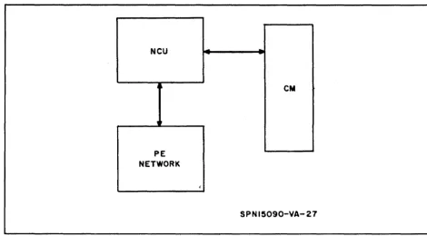
Although the Network Control Unit (NCU) and the Processing Element (PE)
Network appear to be two separate units (see figure 2-1), each with its own
set of instructions, a program interspersing commands for both units will
cause concurrent operation of the two.
NCU
-
--4~ CM
,
PE NETWORK
(
SPN 15090-VA-21
Figure 2-1. Network Control Unit and Processing Element Network
The NCU monitors all instructions. An instruction is brought from Central
Memory (CM) into the NCU. If it is a PE instruction, it is sent to the Network
for execution and the next instruction is brought from CM. By interspersing
NCU commands and Network commands, the two units perform simultaneously.
Suppose, for example, a program contains a PE multiply instruction
(execution time is 13 microseconds). The program can be written so that
I\V\
2-1about 6 NeD commands can be executed during this time. Thus in some cases
most of the FE bookkeeping (i. e., indexing, shifting, etc) can be done without
loss of time.
A program written with interspersed commands will enable SOLOMON II
to obtain the maximum in concurrent operation.
Also in line with the above, the operations of both the NeD and the FE
Net-work can be executed by the same program. This is due to the fact that all
instructions are extracted from NeD memory and those pertaining to the FE
Network are given to the Network to execute via the NeD, while those
pertain-ing to the NeD are executed by the NeD. Thus one program is capable of
controlling both the NeD and the FE Network either separately or together
(concurrently), depending upon how the two types of instructions are
inter-spersed. It should be mentioned that the main computing power is in the
Net-work while the NeD only performs operations such as indexing, bookkeeping,
and data transfer.
2-2 ~
3. THE USE OF MODE CONTROL
Mode control is one of two methods provided for referencing one or more
groups of PEt s. At any point in the program any PE may be set to one of four
modes (0,1,2,3). Once a PE is set to a mode it has the option of
respond-ing or not respondrespond-ing to a given instruction accordrespond-ing to the PE mode and the
mode control indicated in the instruction (i. e., PE's in Mode 1 respond to
in-structions addressed to Ml but do not respond to inin-structions addressed to
M 0, 2, 3). Thus, the mode status provide s the programmer a means of
con-trol of special situations in a program.
Assume, for example, a weather problem where each FE represents a
given grid point in the system. Assume also that the PE arrangement is a
fixed square> 2 by 2 (this is purely an as sumption, however, as the
arrange-ment may be any configuration). Mode control will provide an effective method
of differentiating between boundary points and internal mesh points in the
square arrangement.
The equation V 2
¢
=
F(x, y) will serve well as an example of mode control.An averaged ¢ must be found for both poles. (Assume we are working with
the north pole. All points have a value for
¢
but only those adjacent to polesare to be averaged.) In a matrix array of PE's the uppermost row is as sumed
to be the north-most row. Mode control provides a method so that only those
PE's concerned with the north row will be averaged and ensures that the
inter-nal mesh points will not respond to the averaging instructions. This method "
is as follows:
a. Set all PE's to Mode 0
b. Set the uppermost or north row to Mode 2
c. Instructions for the averaging routine will reference those PEl s in
Mode 2 only. (This same routine will be repeated for the south pole
cP.)
I\V\
3-1Therefore, in the above example, mode control provides boundary control.
The relaxation routine in a weather problem also depends on mode control
for its completion. For each grid point there is an original as sumption for <p ..
Lj.;
=
r
This If; is then substituted and the resulting R~
is tested against45 m 1J
a given E. If E - R ..
<
0, convergence has not occurred. A new value of1J
4;
is computed and the loop is recycled; i. eo, the new value of4;
is substitutedand convergence is again tested.
The PE's are originally set to Mode O. At the end of the first cycle, any
PE which has not converged is set to Mode 2. This is accomplished by
check-ing the sign bit; i. e., any PE with a negative result is set to Mode 2. The
mode status is then tested. If any PE is in Mode 2, all PE's are again set to
Mode 0 and the loop is recycled. Only when all PE's remain in Mode 0 at the
end of a cycle has convergence occurred. Thus mode control allows the
te rmination of a loop.
The above two examples for the use of mode control (boundary control and
loop control) are a small sample of its many uses.
The availability of only four mode states may seem a restriction on the
programmer but the ability to store and load mode states (mode map) into
and from the PE core memory provides the programmer with unlimited
(actu-ally limited only by the amount of core storage available) mode states. The
PE instruction set contains the necessary instructions for mode control. In
addition, the programmer can change the mode state of PEt s based on the
result of an arithmetic operation, overflow conditions, bit checks, etc. Thus
mode control provides the programmer with a powerful method of control.
3-2
I\V\
4. GEOMETRIC CONTROL
A second method of idling some PE's is to use two registers which exert
what is called geometric control. One register, called the row select
regis-ter, is associated with the rows of the square array of PE's and the other,
similarly associated with the columns, is called the column geometric
regis-ter. The row geometric register contains exactly one bit corresponding to
each row of PEl s. The column geometric register contains exactly one bit
corresponding to each column of PEl s. The contents of the geometric control
portion of the Machine Option register determines which of the four geom.etric
possibilities is to be effective during an instruction:
a. Neither register is active
b. The row geometric register is active and the column geometric
register is inactive.
c. The column geometric register is active and the row geometric
register is inactive.
d. Both registers are active.
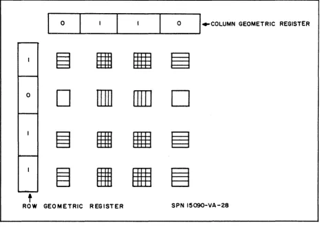
When either register is active, its effect is as follows. If the k-th bit in the
row (column) geometric register is a 0, then the PE's in the k-th row
(col-umn) are all idle. If this bit is a I, then these PEls are active, though still
subject, of course, to mode control. When either of the registers is inactive,
it does not idle any of the PE network; i.. e., an inactive register is equivalent
to a register filled entirely with l's. In the 4 by 4 sample network shown in
figure 4- 1 below, the PE's behave as follow s as a re sult of geometric
con-trol. In case a listed above, all 16 PE's are active. In case b, all 12 PEls
which are shaded with horizontal or with both horizontal and vertical lines
are active. In case c, the eight PE's shaded with vertical or with vertical
and horizontal lines are active. In case d, the six PE's which are shaded
with both horizontal and vertical lines are the only ones active.
~ 4-1
~_O
_ _ ... _ _ _ -,-_ _ _ _ ... __ O _ _~I"COLUMN
GEOMETRIC REGISTERo
D
IIJ]
illD
D
t
ROW GEOMETRIC REGISTER SPN 15090-VA-28
Figure 4-1. 4 x 4 Sample Network
Geometric control has many uses. The following examples will
demon-strate some of these:
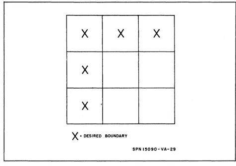
a. Establish Boundary Conditions (see figure 4-2)
Presume all PE's are in Mode O. The GR would then be loaded with
con-stants (k where k
=
011). An instruction will then set all activated PE's toMode 3, thus establishing the boundary conditions with all boundary PE's in
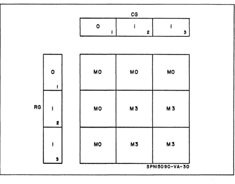
Mode 0 (see figure 4-3). Actually for this simple case the programmer can
specify that geometric control is active (both) and the mode state of the
bound-ary PE's are immaterial.
b. Input of Data
As a continuation of a, suppose data is to be sent to boundary points only.
U sing the L-Buffer, where data are stored in locations 0, I, . . . 31, an
4-2 ~
x
x
x
x
x
,X :
DESIRED BOUNDARYSPNI5090-VA-29
Figure 4-2. Boundary Conditions
instruction will transfer the contents of the L-Buffer to corresponding active
PE's (as designated by l' s in CG and RG). Thus data is brought into the
Network under geometric control.
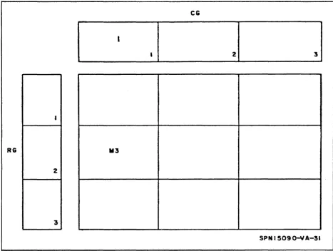
c. Output of Data
If only certain data is to be output, geometric control is employed to
transfer the data from the FE Network to the L-Buffer (see figure 4 -4).
Suppose the PE containing the desired information is in Mode 3. Any
instruction will command any column with active PE's (i. e., with a PE in
Mode 3) to place a 1 in the corresponding bit position of the CG. The next
instruction, with the combined use of geometric and mode control, will
trans-fer data from the Mode 3 PE in column 1 to the L-Buftrans-fer for output. In this
example geometric control provides output control.
~ 4-3
CG
o
0
MO
MO
MO
,
RG
I
MO
M3
M3
2
I
MO
M3
M3
!
SPNle090-VA-~O
Figure 4 -3. Boundary PE's in Mode 0
4-4 ~
CG
R6 .. 3
2
3
SPN 1509o-YA-31
Figure 4-4. Transfer of Data from FE Network to L-Buffer
~ 4-5/4-6
5. USE OF THE BROADCAST REGISTER
One of the features of SOLOMON is the Broadcast Register (B); a 20 -bit
register which transfers data from Central Memory (CM) to the PE Network.
Suppose a problem requires constants for its solution. These constants
are stored in CM. One instruction transfers the data from CM to B thus
making the constant available to all PE's. After the constant is in B, it may
be used for various arithmetric operations in addition to being broadcast to
all PE's. By using B the PE memory is preserved (one memory location as
compared to one per PE).
The register is also adaptable (as an option) for special usage 0 For
exam-pIe, problems using polar boundaries require values to the north or south of
the base PE. These values corne from neighboring PE's for internal points.
The acquisition of these values for the polar parameters, however, poses
special problems. An easy solution is to use B as a north or south routing
(i. e., provide north and south averaged values) thus permitting polar PE's
to gain needed information.
Thus two uses of Bare:
a. Providing constants for use in all PE's
b. Providing north or south routings for special problems such as
supplying polar values when needed.
~ 5-1/5-2
6.
INTERCONNECTIONS BETWEEN PElSAn important feature of the PE network is that neighboring PE's are
connected so that each PE has available, as well as the data in its own
mem-ory, the data in the memory of its four nearest neighbors.
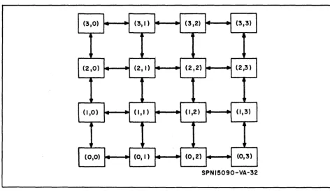
Ordinarily, the PE's are thought of as lying in a square array in a plane
(see figure 6-1). The basic SOLOMON network is considered to have an
array of 32 by 32 PEls. Without any design changes, however, modules of
256 (32 x 8) PE's can be added to or removed from the network. Thus the
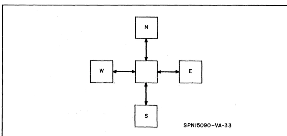
minimal network contains 32 by 8 PEl s. For a PE which is interior to the
array, the four nearest neighbors are designated as east (E), north (N), west
(W), and south (S) (see figure 6-2). The PEls along the edges have only three
nearest neighbors, while those on the corners have only two.
SPN 15090-VA-32
Figure 6-1. PEls in Square Array in a Plane
~ 6-1
N
j
,
W
--
-
-.
E)
J
Ir
S
SPNI50 90-VA-33
Figure 6-2. Four Nearest Neighbors
6-2
7. INDEX REGISTERS
The SOLOMON II System has seven index registers. The two main uses
of the index registers are to provide loop control and to provide a means of
picking an element out of an array.
The following example illustrates the use of an index register (in this case
Xl) to provide loop control. Suppose there is a series of N instructions that
must be performed Z times. Then the following loop could be constructed:
Begin
TIX
Inst. 1
Inst. 2
Inst. N
SIX
JXZ
XI, Z
Xl, -1
.;., X I, Begin
(Set Xl to Z)
Subtract I from Xl
(if Xl';' 0, jump to Begin)
The loop is performed Z times. When the Z -th time is completed, Xl
=
0and the next instruction following this loop will be executed.
Suppose that there exists a one dimensional array of n elements stored
s equentiall y as:
address
address
+
1address
+
2address
+
n-lELEMENT 0 ELEMENT 1 ELEMENT 2
ELEMENT n-I
~ 7-1
Suppose it is now desirable to perform an operation on the Z -th element of
this array
(0
<
Z ::. n). Also suppose that the desired operation is a TMP.This could be performed as follows:
TIX X, Z -1 Set index register X to Z-l
TMP ELEMENT, X
The address of ELEMENT is added to the contents of X and the element in
this new addres s is transferred to the P register. This element is indeed the
desired Z -th element of the array.
Since the SOLOMON II System has seven index registers, it is possible to
have control over many loops and arrays with a minimum of manipulation.
As a final comment on this topic, anyone of the seven available index
regis-ters can be used to control loops in either the PE Network or in the Central
Control Unit. Hence the programmer has available seven index registers
that can be used to index PE instructions or NCU instructions.
7-2
(\V\
8. DOUBLE PRECISION ARITHMETIC
8.1 DOUBLE PRECISION MULTIPLY
This program was written for application to problems which require
great-er than avgreat-erage precision. A double precision numbgreat-er (2
+
38 bits) isrep-resented by 2 (1
+
19) bit numbers. A restriction on the location of the mostsignificant and least significant 20 bits is not necessary but in general they
will be located in sequential memory locations. A double precision number
can be expressed as the sum of the most significant 19 bits plus the least
significant 19 bits as A
+
~A. The product of two such numbers yields theidentity:
(A
+
~A) (B+
~B) == AB+
~AB+
A~B+
~A~B (8-1)In fixed point form, (A
+
~A)
can be expressed as (Ao Z19+
~A·
2°). Thusthe right side of equation 8-1 can be expressed as in equation 8-2
ABoZ38
+
~AB.219
+
A~B·219
+
~A~B.
2° (8-2)Note from equation 8-2 that the sign positions of the numbers will line up
as shown in figure 8 -1.
One obtains the 80 -bit product by adding the appropriate single length
blocks of 20 bits. Care must be taken to preserve the carry bit from the
addition of each pair of blocks. The carry bits are added into the next
col-umn of blocks. The use carry (UC) option on the addition operation adds in
the carry flip-flop. In general, it is impossible to get overflow in the multiply
operation. However, since the 2' s compliment representation is used for
negative numbers it is pos sible to have (-l) x (-l)
=
+
1 which causes anover-flow. This is the only case. It is not J:J.ecessary to sense overflow in the
addition operation except in the final column. If overflow occurs in the
second or third column, only the sign bit will be wrong. But these are changed
to match the sign of column I by the algebraic shift of 0 places at the end of
~ 8-1
AB ~A6.B
i A.
'"
A.
~
/
lsi
lsi
2lSi
:3lSi
4I
~ABi A.
\
IlSi
2lSi
3I
A~BlSi
;..
I
2
lSi
SPN 15090 - VA-:34
Figure 8-1. Sign Position of Numbers
the program. If overflow occurs in column 1, . a jump instruction transfers
the computer out of the program to an instruction called OUT. (OUT must
be designated in the main program. )
The resultant is stored in four locations called Rl, R2, R3, and R4. Rl
is the most significant 19 bits and R4 is the least significant. Note that the
same digit occupies all four sign bits located within the 80-bit result.
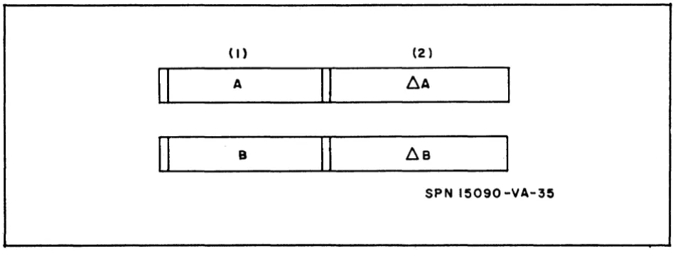
8.2 DOUBLE PRECISION ADD
This program was written to accompany the double precision multiply
program. A double precision number is expressed as (A
+
~A) where A isthe most significant 19 bits and ~A is the least significant. Since the
sign bits of two double precision numbers line up, the numbers can be added
in blocks of 19 bits (see figure 8 -2).
The carry from column 2 is added to column 1 by the U C option on addition
The necessity of detecting overflow is left to the programmer. The most
significant 19 bits of the result are stored in the P Register and the least
8-2
tW\
(I) (2 )
II
AII
~AII
BII
~BSPN 15090 -VA-35
Figure 8-2. Sign Bits of Two Double Precision NUITlbers Line Up
significant are stored in the Q Register. The double precision add tiITle is
11 ITlicroseconds.
~ 8-3
n
o
:I
"CI C r+ CD ~ (I) '< en r+ CD:I
en T1 2
~
PROGRAM: DOl/8d PR£OS/o/IJ ;;JutlliJLyDATE:
LOCATION INST. OPTIONS 9 10 15 16 21 22
-10 V'y,I.o II)T
,Il< 10 / A
;\'\10 / p,
I, PI"" I / A"., I
Irlf.)l!l-l I 1.418 2
J
ITIKIQ J ~
IMIQ / 116
1/r:J/ot I 1t1LJ. Ip, .2.
ITQJVI I 1+4 /~ 3
TRo / DA
fY Q / If)
ITPI- I L1.l4 f.2
Tlo};} I AlII 8::{
rlRI(j / Aft
vllo / llO
IT pi};} / fi4-AIAI2, ITlfJ ;V I I Rlt! I
I
@
e'II CODING FORM
JoLOI'1(),A/ 8-4
PROGRAMMER: l( J/J/r'J£5 8e~Wc7T PAGE J OF 3
ADDRESS AND COMMENTS SEQUENCE
7273 80
IF· A J~ II-I-£\. 6. Ll.4113 Lilt-Itdi3 IT / ME.
J
I n
1 J
11.
2
j ~o
""2
'2
1.)
/ ~ 0
2
,
J :jo
117
t--
r-r-I "Bli)' u 1:5 I.t= r
C")
o
3
~c
...
CD...
T1 2
rx;
20001. I
PROGRAM:DOl' ~t PRECIS/CA.) )1/Ji-TIPLVDATE: LOCATION INST. OPTIONS
9 10 15 16 21 22
rn IMlp )
.-SQi: I
Tli? P I b.A IL'iB3
Alp I LlA 1~3
OSC /
TlnlM I rf1 IgRIV
Alp I AA IRI~
TIPM I
R3
TIRlp / CA I? ~IY
AP I AL312
IQsc /
IT I ) M / Cit RIRlv
/+P / flA 52
iY25L /
IA P / Ai'. Ir,,12
T P iv1 / 1\2
IE PQ J
lAP C I {It IU< 'I
IA
p () I 3A-BIIJfIlfJ / 30 Ulr
I
TPfV1 / IR I
IT 1\ Q I lIZ L
SP fJlR A I 0
Irilrl I
R2
IT
k ('
I R3I~p 0/<113 /
TOM / R.5
@
SOL.iJ;V!r.;/V JI CODING FORM 8-5PROGRAMMER: /? . .J/}/1£S 13£NN£7T PAGE 2 OF 3
ADDRESS AND COMMENTS SEQUENCE 7273 80
IE,' IRI3 !R 2 ( I AD 1 j lsT Is lib INS T I IM!t:
Q-~o i:L
212 12-c.-~4' ~ 12 1.1L 2 22.
c-"'Q ).
2 2
C -." it) "2
}
12
IQ-
-,p1-2
I 2
-r-n
o
3
~c:
r+
CD
...
T
1 2
iX
2000( I
PROGRAM: DOI/BI.-E p!?eC1SIO,f,.,'_ .40.0 DATE:
LOCATION INST. OPTIONS 9 10 15 16 21 22
A Din
171R p I !LilA
ItP I /18
IE plQ i
II R P / A
IAPlc / I i IB
I
I
@
SOLOMON' JI CODING FORM 8-6PROGRAMMER:
K
J,q/V1£~ 8£.NiVETT PAGE 3 OF 3ADDRESS AND COMMENTS SEQUENCE
7273 80
Ii J Jl1 e..
12
12
Ipl-~IQ 217
ll2
.1l1
-/ I ,C ~5 £c..
9. INPUT/OUTPUT
9.1 GENERAL
In general, the I/O operations in the SOLOMON II System are quite
conven-tional in that data channels are used to transmit data between central memory
and the standard peripheral devices such as magnetic tape, disk, high speed
printer, and typewriter. However, the transmis sion of data between central
memory and the PE is rather unique. This transmission of data is
accom-plished by a serial-to-parallel converter called the L-Buffer. The actual
details of transferring data is covered in SOLOMON Technical Memorandum
No. 25, "SOLOMON II Physical Characteristics. "
To store information into the PE memories, the information must fir st
be read into central memory by tape, punched cards, etc. From the central
memory, it is transferred to the L-Buffer and from there to the PE
ITleITlO-rieso
The output from the PE Network process is the exact reverse procedure.
The desired information is transferred from the PE memories to the
L-Buffer and from there to the printer or other peripheral deviceso
902 CONTOUR LINES
The final output for many forecasting models are contour lines of weather
parameters such as pressure and temperature. For example, at the end of
the 500-mb forecast, the desired output consists of the 500-mb height field.
Assume that it is desired to obtain the contour for 500-mb surface at 19, 000 ±
±50 feet. The following series of instructions can be used:
MSI
TMB
TRP
Set all PE I s to Mode 0
Load Broadcast Register with 19,000
Load P with height
~ 9-1
SR
TMB
MSLA
B (P}-(B}-P
Load Broadcast Register with 50
Set all PEls in which
t
P 1<
B to Mode 2Each PE has two flip-flops to store the mode status and for this case any PE
which had answered yes would have a (1 0}2 combination in its mode
flip-flops 0 The Mode 2 PE' s will define the contour line and this line can be
dis-played on a TV tube by the use of a display device o The same procedure can
be used to obtain the remaining contour lines of the height field and then a
picture of the TV tube can be taken for the final output. This process of
dis-playing contour lines could be a continuous process and would allow the
Mete-orologist to observe the progres s of the forecast as it is being generated.
This procedure would seem to be a powerful tool for a Meteorologist working
to experiment with different models, different finite differencing
approxima-tions, or the general heating of the at:mosphereo
The contour output scheme should also provide a speed advantage over the
present method of feeding the data to an analog plotter. However, no time
estimate is available at this ti:me.
9-2
fun
10. VARIABLE GEOMETRY
Three alternative configurations, de scribed below, are available in
addi-tion to the planar one described previously. The choice of the 4 possible
configurations is made by the programmer. (Additional configurations are
available as a special option o )
By joining the east and west edges of the planar array, the network
be-comes cylindrical, with open north and south ends. Using figure 6-1 as an
example, a cylinder would be formed by connecting the following pairs of
FE's: (0,3) and (0,0), (1,3) and (1,0), (2,3) and (2,0), (3,3) and (3,0).
Similarly, by joining the north and south edges of the planar array, a
cylinder with open east and west ends is formed.
If the connections specified in the last two options are made at the same
time, the figure becomes a torus. In this case, every FE in the network has
four neare st neighbor s.
The possibility of selecting one of several configurations, depending on the
problem, is attractive.
For example, in a physical problem which is most conveniently described
in cylindrical coordinates, the connection between the two opposite edges of
the planar array is automatically made. Without this provision, program
steps would have to be written to create this connection artificiallyo To join
the most easterly and most westerly columns by programming would involve
the following: every time all the FE's consult their western neighbors, the
same instruction can be exe cuted by the FE's in all columns except the most
westerly one. This column 's west neighbors are in the most easterly column.
At least two more instructions (as seen later) would be required to get the
required neighborly information from the east side of the square array to the
west sideo
~ 10-1/10-2
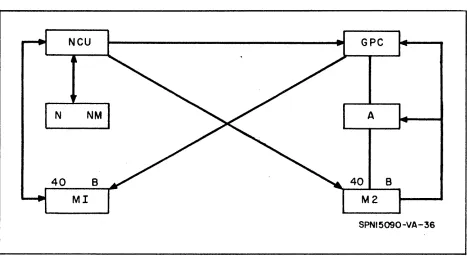
11. COMMUNICATIONS BETWEEN UNITS (NCU, GPC, NETWORK)
Communications between the Network, the Network Control Unit, and the
General Purpose Unit are outlined by the schematic diagram shown in figure
11-10
SPNI5090-VA-36
Figure 11-1. Routes of Access Between NeU, GPU, and Network
In the diagram above:
N, NM PE Network and PE memory, respectively
GPC General Purpose Control
Ml Memory for NCU (40 bits)
M2
A
Memory for GPC (40 bits)
Arithmetic Unit (associated with GPC) Both A and GPC together comprise the General Purpose Unit.
~ 11-1
As seen from the above diagram, direct access is available for the NCU
and GPC to each other's memory. This implies that the NCU is able to
com-municate directly with the GPC memory and conversely, the GPU is able to
communicate directly with the NCU memory. Communication with respect
to the Network is supplied only through the Network Control Unito The PE
Network does not have access to the General Purpose Unit directly but must
communicate through the Network Control unit, then to the G PU by the
in-struction HELP. All data transfer from or to the PE Network must take place
through the NCU {via either the L-Buffer or Broadcast Register}o Also, all
indexing instructions to the PENetwork are executed and controlled by the
NCU onlyo
11-2
~12. NUMBER OF POINTS PER PROCESSING ELEMENT
Each PE is capable of handling any desired number of grid points on a
finite difference mesh (within the required storage limits for those points)o
In general, this grid point - PE allocation is determined mainly by the
re-quirements (size) of the finite difference network being solved and the number
of Processing Elements available (for this report 32 x 32 or 1024 Processing
Elements)o The allocation can be as small as one grid point per PE or many
grid points per PE subject to the storage limitations of those pointso The
only restriction imposed on this grid point allocation other than storage is
that it be uniform throughout the entire Network, otherwise some special
programming considerations must be applied.
It might be mentioned here that as the number of grid points per PE
in-creases, it becomes more desirable to use some form of a loop to avoid the
tedious task of straight line coding for all points, provided the same
instruc-tions apply at each point. This technique will result in a slight time los s
due to the indexing instructions necessary to control the loop but could be
very valuable in situations where the grid point allocation per PE is very
large. In writing a loop for a set of points with a Processing Element, there
are two factors which must be considered.
a. The routing must be changed for various points (implies modification
of the routing field in the instruction).
b.. The positions with the PE must be incremented (implies indexing
of positions).
Of the two factors given above, changing the routing appears to be the most
formidable.. This can be handled by either of the following two methods:
~ 12-1
a. The routing can be indexed by indirect addressing (SOLOMON
Proj-ect of Technical MeITloranduITl No. 23 "SOLOMON II PrograITlITlers' Reference
Manual"). This method consists of placing all of the required addresses to
be used for each position in a sequential table in Central Control Memory
and using indexing controls on the PE Network to provide the correct
ad-dresses associated with each position in turno This corresponds to a "table
look-up" and could result in a slight loss of time since the PE Network may
be inactive while the fetching procedure of the correct addresses is being
performed.
b. Indexing the routing can be avoided by simply coding a separate
subroutine for each position (or groups of positions), controllable by
index-ing from Central ControL Each separate subroutine would contain the
neces-sary operations and routings required for the calculations to be performed
at that particular position. For the case where there are many points per
Processing Element, a single subroutine can be written to take care of all
interior points within the PE while the necessary subroutines can be written
to account for the peripheral PE positions (one for each corner and one for
each side containing other than corner points). In general, the corner points
will require special treatment since it is at these positions where the greatest
variation in routing will occur. An exaITlple of this type of program for the
eight-point-per-Processing-EleITlent case is illustrated in the coding for the
initialization section of the saITlple fore cast probleITl which is presented later
in this memorandum.
12-2 ~
13. ASSOCIATIVE MEMORY PROPERTIES
The purpose of this section is threefold: to assign a definition unique to
as sociative ITleITlory prograITls, to develop and illustrate an example of
as-sociative ITleITlory prograITls, and to provide a flow chart (see figure 13-1)
and prograITl coding for a ITlore cOITlprehensive studyo
START
C OMPAR E MAGNITUOE
MASTER WORD WITH DATA WORD
RETAIN M3 TO
I DENTI FY ow-MW
RETAIN MI TO
IDENTIFY DW< MW
P. E. (5) GREArE5T
NUMBER MATCH DIGITS MO"M3
RETAIN M2 TO IDENTIFY Dw>MW
SPNI5090-VB- 3 7
Figure 13-1. Associative Memory Flow Chart
To define associative ITleITlory prograITls, consider a norITla1 prograITl
(with or without parallel proce s sing) 0 The prograITl will call for spe cified
~ 13-1
operations to be performed which involve spe cified value s stored at spe cified
memory locations. In contrast, as s ociative memory programs may utilize
a parallel process machine to perform unknown functions with unknown data
stored in unknown memory locations.. The term unknown here implies that
the three involved factors are not rigidly designed into the program and are
not determinable through visual examination of the program coding. During
the development of the model program, the above mentioned three unknowns
will be reiterated as they become a set of interrelated factors which establish
the function and effect of the program.
In examining the exact function or purpose of the model program, consider
that it may represent one facet of a complex integrated system of data
proc-e s sing rathproc-er than bproc-eing complproc-etproc-e and indproc-epproc-endproc-ent. That is to say, thproc-e
pro-gram will represent to an experienced propro-grammer or systems analyst a
simple example of data maneuvers and comparisons which are now ordinarily
handled in a very awkward and time consuming manner.. Supporting this
state-ment, the several major accomplishments of the program will be listed:
a. Simultaneous magnitude or similarity comparison of a large set of
data words to some controlling factor (herein called the master word). This
corresponds to the first function block on the attached flow chart.
b.. Categorizing of the data words into one of the following four groups:
(I) Data word
=
master word(2) Data word> master word
(3) Data word
<
master word{4} Greatest similarity based on matching bits or absence of
bits in corresponding bit positions.
c. Controlling which classes of data, or combination of classes, will
be assigned to further processing and which classes are not to be retained
as unique categories for selection.
Consider that the model program will first compare and categorize each
data word (hereafter called DW and stored in processing element memory)
13-2 ~
by a few simple steps relating the DW and the master word (MW). First
simultaneous subtraction is performed and the difference MW -DW is stored
back into each PEe The magnitude of the difference is examined to establish
one of the following three relationships:
a. MW -DW
=
0; Equalityb. MW-DW
<
0; DW > MWc. MW-DW> 0; DW
<
MWActually, the first two conditions cited are tested for and the third is assumed
through this elimination proce s s. This repre sents the operations from point
A to point B on the flow chart; and as the chart points out, the data is being
categorized during these tests by assigning one of four FE mode settings to
each group of PEls. The operations begin with all PEls set to mode zero
and the following modes are as signed to represent each group:
a. Equality; Mode 3
b. DW > MW; Mode 2
c. DW
<
MW; Mode 1Note that at this point the SOLOMON II has used a half dozen instructions to
compare and categorize 1024 data words in its PE' s by relating them to the
controlling MW. Mode selection would now be capable of assigning any or all
of the data groups to one or more subroutines. The similarity test has not
been made at this point since it would have no meaning when used with the
above three te sts" Equality would obviously mean complete similarity"
How-ever, a lesser than word and a greater than word :may be equally similar to
the :master word.
The program now utilizes 3 of the 40 sense switches set from the
SOLOMON II Console Panel to deter:mine whether the data groups should
re-tain their unique :mode setting or be returned to Mode O. A 4th switch is
tested to see if the si:milarity test is desired.
B on the flow chart.
These processes begin at point
~ 13-3
At point D, an interesting similarity test is achieved by simultaneously
creating a word containing bits in all matching digits and then adding the bits
to determine which word or words are most similar to the master word.
First the matching bits are established by the Boolean AND function and
the re suIting word is stored. MW
+
DW is then performed as an OR functionoThis is complemented and another OR adds this and the result of the AND
operationso The results contain bits in all matching digits.
Having identified similarity by FE Mode State 3, the program would now
make the final of several possible exits to the switch test rendezvous point.
This corresponds to point RONDO on the flow charto At this point consider
the as sociative memory program in the light of the original definition. The
unknown function is satisfied by the ambiguity of DW magnitude, sense switch
settings, mode states, etc. The unknown data is the undefined contents of
1024 FE data words. Finally, the unknown locations are illustrated in that,
at point RONDO or other points, data catagories based on magnitude or
simi-larity could be assigned an exit into subsequent processing unique to their
classification without directly addressing a specific location or set of location:
in the computer memory.
13-4
@
- - - C o m p u t e r and Data Systems
~
C")
o
3
-=
c
....
CD
~
PROGRAM: Assoc.., Y1EM¢RY VI (/JDeL. DATE: T
LOCATION INST_ OPTIONS
1 2 9 10 15 16 21 22
ST AIR I.,... HSI 0
TIMiB MA
TRP Is
SR DIW
ITPM T£
il.P
iM S E. 0 3
MS PG 0
2-Msr
0 tSf NSE TS Sr-v
wI\! 1M C(J5
TM"X Cat
Jwll. kl
K1 M51 3 0
1<1
+1
TS SwwiN 1M C~
JvJl K2.
K2 MSI 2 0
K;( + 1 TS Sw
WN It41
JWI7f. K3 K3 MS r 1 0
K3 +1 I
Tis
Sw
wN 1M
JWl. k4
k4 J?i R0
k4 +1 MSI I .2 0
JNA 3 RI~
TRP
BPAR t>IVtj Z()()Q4-1
5T ER
Mf'1 N1
No
1 tJ~ 1 1 1 NDastJ D ¢
@
CODING FORM 13-5PROGRAMMER: "D E L GUSeN'tU s PAGE
1
OF 3ADDRESS AND COMMENTS SEQUENCE
7273 80
M-~M o •
MA Is T t:.R w¢ Rl) TIIZ' BR
MW -~ Ipl ..
Dw 1 S PA
irA
~0 RD.ST ¢R E MW - \ ) 1\11 ..
oj S -~ PL..
Dw =MW MO -~ M3
DW '> Mlw MO -~ M 2. ..
pw <M W, MO - + Mil ..
BE: k; IN SW I T C.H
s£
NS INGN£flT
W·
lMI\ M;to
00-
-
~I R 1 SeT T¢ 1 •
r F sso I¢N -~ M+1
E.~ uA 1-1 ,-y ;8 A C.K T¢ 1-10
C¢ N 2 =0 10 0 -
.
GR rEA T ER ISA c. I( T¢ MO.
IDW <11 w' 1M -~HO
SiS 3 ~FF ¢M IT BIT MA 'C.H ttl:: ST.
EG; UA LI
tTy
IS GNMD!
6 f IS.t>f¢ EQ vA L I Ty TE ST EA c. H DI ~ r IT •
n
o
3
""CI
C
..
CD...
@
PROGRAM: Asso<:... I-'1EM~RY MPDEL DATE: T
LOCATION INST. OPTIONS
I 2 9 10 15 16 21 22
,p
1M YE MPlTR P B
P0R ()\Aj
t-Jp
P<Z5R T£ MPt
T'Z NM IE 1'11' 1
~1 NM
TE
~ plJLI¢ ¢Ip rri!G £PQ
ML SI<zi(2S 0 1
A? 1 C0 N~
Alp IrE f\1 pi1
TIPIM Tfi MPl
MSI 1 C
T-lP 0
AlP raS NS
Af' 1€. MP2
TPM TE MP1.
MS£ Ie 2.( cDNb
JNA 2
Ex
rlT1lePQ 0
Isp RL
11
I ~p
L<.ZI a>lp
If
Xl1T1
1M S I 12 10 Tl'P 0liRIQ / £ MPl
SQC. 4
fillS LQ 0 1
JNA 1 KS
K5 MSI
@
CODING FORM 13-6PROGRAMMER: Dr:L GUSE!NILlS PAGE
2
OF "3-ADDRESS AND COMMENTS SEQUENCE
7273 80
MA-Te.. i-Il "'ft D1 Gi
rs
I .... ~ 8 1 TS.B 1: TS N¢"" IN
P .
N¢ IN 6'I T AD De: R •tJ~w Cy c.Le: eo UN TE. R "
Br IS -~IQ
ILS j)Q
=
1 CH hN GE. M¢ DE
f--ST dRE ~ liT Ie. ¢ UN T
ST (l) R e: c.v e.Lt:. C¢ UN T
BIT C.C2l uNT N¢IN 1 I'l T£ MP1
BIT c¢ UNIT T¢ Q Q~ 2.0 :;( 00·-
-
- 10 10 01)MO 1-7-Ml 1 F 81 T IN
D
I (lIT I S rt>F TE-MFlCO)
o
3
-=
c
r+
CD
...
... ...
VJ I
-J U1 0 "-..
-..D ...
0 VJ
»
I00
PROGRAM: ASSoc., i'v\~NI ~R'l' M¢[)EL DATE: T
LOCATION INST. OPTIONS
1 2 9 10 15 16 21 22
II< S +1 SQC 1
19
rvlS LQ ¢ 1
2-JNA 2 kb
k6 HSI 1 2.
Iklb +1 SQc. 12 19
MS LQIQ! 2 '3
JNA 3 KI1
IKI'1 MS 1 2 3
IlC 7 +11 SelQ 3 ,Iq
MS 1 112 C>
MS LiG;OJ 3 1
JNA 1 Kg
il<
9 HSI 3 1KG +1 SQC 1 lq
rvts LiG ¢ 1 2. Jlt-t A 2- K,q
Klq Mis I 1 2 ,K Pl +1 MSI I 3 0
M S I 2 j
JP, R~
RI~ ~ID0
I
i
ZOOCIol-1
@
CODING FORM 13-7/13-8PROGRAMMER: DE L GUSENIUS PAGE ~ OF 3
ADDRESS AND COMMENTS SEQUENCE
7273 80
1
1
~
,- 1
1
PE.. I{ S) WI TH
aN
tv1B -~ 113,ND~ SE LE CT Eb J)A fA N0w' MA Rk ED,
IF< E ND E 2. V0 LlS p¢ lNT ALL R¢ UT IN £is
14. SPECIAL REGISTERS
The SOLOMON II System has the following special registers available:
M¢
CG
RG
B
SL
SS
DL
DS
Machine Option Register (geometric control and edge conne ctions)
Column Geometric Register
Row Geometric Register
Broadcast Register (Option No. 1 or No.2)
Sense Lights Register
Sense Switch Register
Data Lights on Arithmetic Unit Register
Data Switches on Arithmetic Unit Register
The SL and SS Registers are located in the following positions:
' .. 4 - - - 4 0
~I
SS 1 1 1 1. 0 0 • 0 • • • •• 11
SL 0 0 0 00 • • 0 • • • • • • 00
NCU
1401~--20
SS 1 1 1 1. 0 • • 0 • • • • • 1 1
SL 0 0 0 O ••• 0 • • • • • • 0 0
GPU
The DL and DS Registers are located in the following positions:
4 0 - - - - -...
~1
DL 1111110 •••••••• I I I
DS 0 0 0 0 0 00 • • • • • • • • 0 0 0
A
o
39
~ 14-1/14-2
IS. SOLOMON II CODING OF BAROTROPIC MODEL WEATHER STUDY
This section deals with a recent weather study program. written for the
SOLOMON II System.. The new program. is a follow-up to the SOLOMON
program. presented for the Barotropic Model; Technical Mem.orandum. Noo 14,
6/12/63, (see flow chart figure lS-1). Unlike the SOLOMON System.,
SOLOMON II is a single address m.achine of fixed word length (20 bits).. Add
tim.e has been decreased by a factor of 10 and multiply time by more than a
factor of 42. New instructions have been added and the m.nem.onics of the old
instructions have been changed. In short, the present program. is
consider-ably different from. the old one.
The data for the first data point of each PE is programm.ed and included
in this section. Program.m.ing for the rem.aining points is sim.i1iar 0 In the
previous program, a four-point-per-PE allocation was used. The same is
true for this case.
The execution tim.e for the present program is obtained by m.ultiplying the
tim.es for the appropriate sets of instructions by 4 and adding in the tim.es
for operations pertaining to all points. The com.puting tim.e for the IBM 7090
was cited in the previous report as approximately 1. 61 x 106 microseconds.
The SOLOMON II com.puting tim.e for this case is 804 m.icroseconds.. This
gives an overall speed ratio of m.ore than 2000/1 in favor of the SOLOMON II
System..
In this program., an attempt was m.ade to keep the sam.e variable nam.es
for quantities as were used in the previous report.. On the first page, '11 is
com.puted for point No.1. The second page has the instructions for
com.put-ing J ('11,
cb),
V
2 cbk+
1 and cbk for point No.1. The subscripts are adjusted in~ lS-l
r---~YE8
J (
'I, '"
I' [(
'IE - '1W
I
("'N- "'91 - ( 'IN - 'Is )(
"'C
"'W
I]
V
2 4>t+l.
V
2 4>'-1 ... 26.
t J('7.4»
4>K • 2rjlt _
~t-IV
2 c/lt-1 •v
24>t,
V
2 ~t. V2;t+
INO
NO
SPN I!S090-VB-!8
Figure 15-1. Flow Chart
15-2
the variables for later use. The relaxation process is programmed for
the first point on page 3. The fourth page contains the test for convergence
in all PE I s while the last page lists the instructions for re setting the
sub-scripts. The exe cution time s for individual instructions and sets of
instruc-tions are listed in the program.
~ 15-3
n
o
3
~c
r+
CD
...
PROGRAM:
T
LOCATION
1 2
~
I
k;i:IJTflE/?
INST. 9 10
Tlge
MSQ
;iRlc i.N11r::
IA IP
IT!IVIP
I
5TtJOY DATE:
OPTIONS 15 16 21 22
Co
I,IV p ()!r IF'IA frio In p Iwo
A
"
III INID IFIL i
J I.e j - I
I I.e I
/ If'T All
@
5()LQ1'10IV1I
CODING FORM 15-4PROGRAMMER:
R.
J/1It1£S l3eNIVEIT PAGE / OF ~ADDRESS AND COMMENTS SEQUENCE 7273 80
In ~ vL I<p lit 1+lf 17 j l#l'p
'~ D F olR i ' ' )
/I II
2.2-\]"1.-14>" I)
f -I j' I()
If " " 2
1)1 .. IJ
J i f
-:i4 0 Ie;!", I/'
@
n
c
3
'1:1 C....
CD...
T PROGRAM:LOCATION
1 2
')t I I " !"/E4THEk INST. 9 10
iT lIZ IQ
IM51Q
rlRip SR
TIM P
IIR P
SR-E.P Q
IMC
ITfV1l""
,PY! TR P
5 F<"
ITP!/Vl liR p Sf( flP 4' MCV
Ie., tZ
IE P "-IHe
AP
fir:' I
TR
pi
r~ P LA~) I~
reM
@
STL.DY DATE:OPTIONS 15 16 21 22
ro /VIP 01 E..' cpnl~'
1\1'--1
It Mo ID E. 111./ oRO r-o IR
fl (I II II
I tV i f IA ~ I
Ell
I!v~I JIf L J
I IAllp N
12-I tJ PH 12
I
I IJf.I. C I
I 07
/ )11 LI
I IIJ If T A 2
/ £1 l!l:2
I ITIF' 1M Pi I !AI :rv P If.! I 3
/ /lJp J-II3
I
i IE MP}
I Jit C J
I
I t3
I
rE
L /I lNo IE. L II P
I INlfl III I /
I /
1 Ie
/f j I
I
"r
If J /CODING FORM 15-5
PROGRAMMER: R.. JI'JmES
at:.
/J /J £ 7T PAGE ;2.. OF (pADDRESS AND COMMENTS SEQUENCE
7273 80
kt
I( 'cP l<- I\] 1-4
r'l-~-N' I~tr \j~ IcP1 _ ~I'J ~ q t'l I I ME.
, I
J 12
II
11...
Yl "
12-Yl . ~ " 12
rn
i;~ ~(- n
" -Ill12-eI> ,~ , l.
~ ~-I '
J<..-PI-~IQ )
en "
II -IY1 " '/ i} l{h~I'-14l
I' ) I ~ C/1
i
/ 1 c:;(~ ., II -In' ,/I){ ~\ I' -~ i- ;
2-J
11. LI-" 1.
Y\ ' , I ' 2],
/11', . -IVI . :-z..
¢' . U-_l "}
<P ' , -/ J
P
~ f"J1G, 71.Ir " - In ~'I ; lId ,;"'1 -Ieb ~' -I ' "I ~
t{ T Imld , ,
PI-['71(.. 1-)
.lILJ Icl,t Irn J I
'V-... I~ -I
2-'J l<t, fl 2
cj.J r 21..
ld r
<to I I c L
n
o
3
-cI
C
...
CD
~ T
1 2
~
2000/<"1
PROGRAM: J~/EI-lT!-1E« LOCATION INST.
9 10
I/R P
'PI<
,Oft'"
I
I
@
Slu[}! DATE: OPTIONS 15 16 21 22
I lAlla ELi
I IDE L J
/ IN j' ELI
'.
'5x.JLO;;1,;;,t) j[ CODING FORM 15-6
PROGRAMMER: g Jlhl,'e5 ;3f!JiUElT PAGE .3 OF (p ADDRESS AND COMMENTS SEQUENCE
7273 80
I I irJ£
1\/ .. leb t -
"
12-V "1..
14
r-/11.-71.- J t+- -t! 'SJ l.. d>t 1 L.
- l -
f-ql5? 2 t " i.E It"
C") o
3
"CS C r+ CD...
TI 2
~ 200C11.-1 PROGRAM: LOCATION Rj 1f3 ; I k~ATJ-IE'j( INST. 9 10
/ T ?: IV /\'1
rl?. '-,
MI-;Io
TRP
5[;7 LA rlpl/"1 TRP IJP IJ(J liP SR. LPfr1 ITR P "'; R.
",IT f1P
IT P t1
11 j fJ ff L
luJ .:, 1'1
IT CJ,t'/
1fr1 "j j
..
.,-~ I ~ i~
IT R 0 1M -)1
lif P
rPM
5Tc/D'L
OPTIONS 15 16
A f} ft I I I I I I I I I / I / / 1 2 2 I / 1 /
@
DATE:21 22
J21£ LI1 Xft TI
Oil-r/-l £1r:IK
frio 10E- 1-1;' () RO If II
KP 11-11 J
:2-ND
eL
j Ik.KP HI '2
kP HI'?
AP
Hllll-kP iJlJ -.z
/'v' D IEL I K
rv D IEIL 11K
I\.' j] IEIL I A'D EL / /(
IEP s
11\ I
28 / IE ip5
-:H EclK
VtL Plf.! Ii
IR I
f3 AL PHIJ
1"-P IHI] I
kP I/~lI J
50L.O)1lMI ]I' CODING FORM 15-7
PROGRAMMER:
R.
J;JIlI£S 8£AlAI£7T PAGE i-/ OF 4:>ADDRESS AND COMMENTS SEQUENCE 7273 80
ITII ME
J
FoR. I
2-If /1
2-d> /'-,
I.-4icP'" 21
'<1 ~ ", II.
4'[11., I ' , ...
dJ K. '+\ I--'
1.\--IdJ K.
1-·CP I..{ '_
2--LJldliC I
17 '4 K
22-i\} 'de
!V'd,K 1
£: b
IJI'- ~r- - V ~ IcjJ ;;.
L-E~ l.
~'-
Il-' l.
c7\ 0
It<.. I
I'\, R I I~ 0
,tf
"-Lt' ~+I -~ ,tK L
ft;!5 .1/ ~ !:s IF r,
C"')
o
:I
"CI
C
...
CD
...
I»
=
a.
C
I»
...
I»
en
'<
en
...
CD
I-'
U1 I
00
T
1 2
~
:I
Z()()Q4.1en
PROGRAM:
LOCATION
I
~j,/eAT'f£tZ STUDV DATE:
INST. OPTIONS 9 10 15 16 21 22
IrlQ
ITIRlc IA Irlll
11'11":" 10 A
lTIM n 2 IRJ
,
@
:]OLOi''lOA>' H CODING FORM15-8
PROGRAMMER:
R
JnME5 8EJI/;VElT PAGE 5" OF (pADDRESS AND COMMENTS SEQUENCE 7273 80
~J.I: .La oP IT J ME..
IFlilK ;;12
~2
if2, J 3')
7.'1 1 <ill- Lr
-n