ISSN(Online): 2319-8753 ISSN (Print): 2347-6710
I
nternational
J
ournal of
I
nnovative
R
esearch in
S
cience,
E
ngineering and
T
echnology
(A High Impact Factor, Monthly, Peer Reviewed Journal)
Visit: www.ijirset.com
Vol. 8, Issue 10, October 2019
Damage Detection in Composite Plates Using
Dynamic Response
M. Al-agamy
1, M.Abo-Elkhier
2, A. A.Hamada
3P.G. Student, Department of Production Engineering & Mechanical Design, Faculty of Engineering, Menoufia
University, Shebin El kom, Egypt1.
Professor, Department of Production Engineering & Mechanical Design, Faculty of Engineering, Menoufia University,
Shebin El kom, Egypt2.
Professor, Department of Production Engineering & Mechanical Design, Faculty of Engineering, Menoufia University,
Shebin El kom, Egypt3.
ABSTRACT: Damage in engineering structures has been of concern to the engineering community for many years. The ability to detect and monitor damage using non-destructive testing in structures and mechanical components becomes very important. Many damage identification techniques have been proposed relying on vibration testing. Vibration-based damage identification techniques rely on the fact that existence of a localized damage in a structure affects the global structural dynamic behavior. In the literature, one of the promising techniques rely on combining a finite element model of the undamaged structure with a set of experimentally-measured frequency response functions (FRF) of the structure under investigation to construct a so-called Damage Location Vector (DLV). This paper aims to assess both theoretically and experimentally damage detection using DLVs. The method is first studied theoretically on a composite plate using simulated damage. Then, it is tested experimentally using free- free and fixed-free boundary condition for a plate with middle damage usingshaker test. The method is improved through the use of FRFs of the undamaged structureobtainedbothnumerically and experimentally in an attempt to overcome difficulties imposed by initial damage and noise. Finally, a case study has been done to assess the DLV technique on composite plates.
KEYWORDS:Composite structure, Damage location vector, Finite element model and Frequency response function.
I.INTRODUCTION
ISSN(Online): 2319-8753 ISSN (Print): 2347-6710
I
nternational
J
ournal of
I
nnovative
R
esearch in
S
cience,
E
ngineering and
T
echnology
(A High Impact Factor, Monthly, Peer Reviewed Journal)
Visit: www.ijirset.com
Vol. 8, Issue 10, October 2019
damagedetection using vibration-based methods can be describedinto two categories: (model and non-model)based approaches. The vibration modal parameters (mode shapes, frequencies, and modal damping) are roles of physical properties of the structure. Damping, mass and stiffness can be obtained by the modal identification procedure; this explains the model-based approaches. S.W.Doebling, and et al. [11] pointed out that the damage can be determined by changes in the dynamic properties or response of structures. The modal parameters are roles of the physical properties of the structure.The changes in the physical properties cause changes in the modal properties. Kayed et al. [12] applied the damage location vector to a real structure using experimental FRFs obtained from non-destructive vibration tests. They improved the method the use of FRFs of the intact structure obtained both numerically and experimentally. Lee and chung [13] presented a method of determining the structural damage size and location using natural frequencies and an appropriate FEM model. Kim et al. [14] proposed a method to locate and quantifya crack in beam structure which named single damage indicator (SDI) .This technique depended on using changes in few natural frequencies. By relating fractional changes in modal energy to changes in natural frequenciesdue to damage,a crack location model and a crack size model were formulated. This has prompted research into the use of heuristic search algorithms in conjunction with numerical models that simulate the structural dynamics to seek the damage scenarios that are associated with a certain change in number of natural frequencies [15]. Agarwalla and Parh [16] pointed out thatthe dynamic behavior of a whole structure changed by the presence of the crack. The cracks in the structure change the frequencies, amplitudes of free vibration and dynamic stability areas to an inevitable result. They studied the effect of an open crack on the modal parameters of the cantilever beam subjected to free vibration.Hassiotis [17] extended the method to include detection in a large number of damaged elements,by using a new optimization procedurebased on Markov parameters. Maitithy and Tribathy[18] used genetic algorithm (GA) to detection and estimate the structural damage from changes in natural frequencies. Pawar and Ganguli[19] detected the matrix crack in thin-walled composite structures based on changes in natural frequencies byused the genetic fuzzy system.Péreza et al [20] showed the results of an extensive experimental campaign conducted to investigate the feasibility of using vibration methods to recognized damages sustained by composite laminates due to low-velocity impact, present work is to investigate the damage detection in laminated composite plate using damage location vector (DLV) techniques. The method is first studied numerically on a composite plate using simulated damage. Then, it is tested experimentally using free- free and fixed-free boundary condition for a plate with damage using mechanical exciter test. The method is improved by using of FRFs of the undamaged structure obtained both numerically and experimentally in a trial to defeat difficulties imposed by initial crack and noise. Finally, a case study has been done to assess the DLV technique on composite plates.
II. GEOMETRY AND MATERIAL
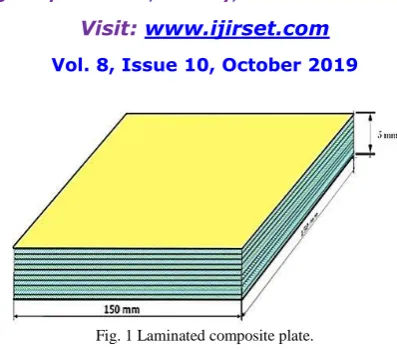
The laminated composite plate used in this investigation of dimensions (150 × 150 × 5) mm as shown in Fig. 1. It is formed from ten layers in which the base material (polyester) is the same while the fibers (E-glass) have different orientation in each layer with the same thickness. Five specimens of composite square plates where manufactures with
the following fiber orientation
ISSN(Online): 2319-8753 ISSN (Print): 2347-6710
I
nternational
J
ournal of
I
nnovative
R
esearch in
S
cience,
E
ngineering and
T
echnology
(A High Impact Factor, Monthly, Peer Reviewed Journal)
Visit: www.ijirset.com
Vol. 8, Issue 10, October 2019
Fig. 1 Laminated composite plate.
TABLE 1SPECIFICATION OF FIBRE AND MATRIX USED INPRESENT STUDY.
Property type
Elastic modulus
(GPa)
Poisson ratio v
Tensile strength
(MPa)
Density (g/cm3)
E-Glass Polyester
72.52 3.5
0.33 0.2
3448 34.5-102.5
2.56 1.2
TABLE 2MECHANICAL PROPERTIES OF THE COMPOSITE PLATE.
Properties Experimental Mixture
rule Longitudinal modulus E11(GPa)
Transverse modulus E22 (GPa) Shear modulusG12 (GPa) Poisson's ratio v12 Volume fraction vf
Longitudinal strength XL(MPa) Transverse strength XT(MPa) Shear strength τº (MPa)
44.4 8.6 4.085
0.3 0.50 618.9
14 28
44.88 8.85 4.057 0.303
_ _ _ _
III. MODAL ANALYSIS USING FINITEELEMENT METHOD
ISSN(Online): 2319-8753 ISSN (Print): 2347-6710
I
nternational
J
ournal of
I
nnovative
R
esearch in
S
cience,
E
ngineering and
T
echnology
(A High Impact Factor, Monthly, Peer Reviewed Journal)
Visit: www.ijirset.com
Vol. 8, Issue 10, October 2019
Fig.2 Finite element model of free-free composite laminate plate
The stiffness matrix of the element can be then formulated as:
𝐾𝑒 = 𝑆 𝑎 𝑇 𝐷 𝑆 𝑑𝑥𝑑𝑦 0
𝑏
0 (1)
Where, [S] is the strain matrix and [D] is the elasticity matrix of the composite plate, a and b are the length and width of plate element respectively, which can be computed according to ʻʻRef. [22]ʼʼ.
Consequently, the mass matrix of element can be formulated as [𝑀𝑒]:
𝑀𝑒 = 𝜌𝑐𝑡 {𝑁}𝑇{𝑁}𝑑𝑥𝑑𝑦
𝑎 0 𝑏
0 (2)
Where, ρc is the density of the equivalent laminated composite plate and {N} is the matrix of shape function.
The Eigen-frequency can be then evaluated from the solution of the characteristic equation for composite plate The initially, the plates were modeled in order to get a first estimation of the un-damped natural frequencies and mode
shapes utilizing finite element type solid65.
The material properties were then entered in the program, and the constraint imposed to simulate a type of fixation. The numerical results using F.E.M were computed for five specimen types and boundary fixations.
IV. THEORY OF STRUCTURAL DAMAGE DETECTION BY DAMAGE LOCATION VECTOR (DLV)
The main idea of damage location vector theory is to find load cases that give symmetrical zero strain field over the damaged elements in both states damaged and undamaged. These vectors can be shown to be included in the null space of the difference in flexibility matrix from damaged to undamaged condition, which is found by applying a singular value decomposition (SVD) analysis of the matrix. The identified vectors are then applied on the undamaged model of the structure and noted the stress in the members. To obtain Weighted Stress Index the stress were normalized by a series of operations. If the Weighted Stress Index is llower than one for a member, indicates that the member is probably damaged.
ISSN(Online): 2319-8753 ISSN (Print): 2347-6710
I
nternational
J
ournal of
I
nnovative
R
esearch in
S
cience,
E
ngineering and
T
echnology
(A High Impact Factor, Monthly, Peer Reviewed Journal)
Visit: www.ijirset.com
Vol. 8, Issue 10, October 2019
𝑀 𝑥 + 𝐶 𝑥 + 𝐾 𝑥 = 𝐹 (3)
Where [M], [C] and [K] are the mass, damping and stiffness matrix respectively.{𝒙} Is the nodal displacement vector and {𝑭} is the nodal force vector.
For a laminated composite plate with and without damage, of negligible damping, the spatial model of the plate needs to consist only of [K] and [M]. The assumption of negligible damping is justified for the case of homogeneous metallic structures, the equation of motion in the case of free vibration then becomes:
𝑀 𝑈𝐷 𝑥 + 𝐾 𝑈𝐷 𝑥 = 0 (4)
𝑀 𝐷 𝑥 + 𝐾 𝐷 𝑥 = 0 (5)
The subscripts UD, D are used to indicate the undamaged and damaged structure respectively. Damage will be considered to result in a reduction in stiffness only, hence[𝑀]𝑈𝐷 = [𝑀]𝐷.
Let [Z (Ω)] be the dynamic stiffness matrix,
[α (Ω)] be the reacceptance frequency response function (RFRF) matrix at a particular frequency Ω and the kth column
of this matrix be denoted by {α (Ω)} k, where:
𝑍 Ω = 𝑘 − Ω2 𝑀 𝑎𝑛𝑑 𝛼 Ω = [[𝐾] − Ω2[𝑀]]−1
Then it follows from the orthogonally of the dynamic stiffness matrix:
[𝑍(Ω)]𝑈𝐷 {𝛼𝑈𝐷 Ω }𝑘 ={𝛿}𝐾 = [𝑍(Ω)]𝐷 {𝛼𝐷 Ω }𝐾 (6)
Where {𝜹}𝒌 is a vector, the elements of which are zero except the kth element which is equal to 1. The dynamic stiffness matrix before and after damage can be related as follows:
[𝑍(Ω)]𝐷 = [𝑍(Ω)]𝑈𝐷− ∆𝑍 Ω (7)
Where [DZ(X)] represents the difference in dynamic stiffness matrix between the damaged and undamaged structure.
ʻʻ(6)ʼʼ can be rewritten as:
[𝑍(Ω)]𝑈𝐷 ({𝛼𝐷 Ω }𝐾− 𝛼𝑈𝐷 Ω }𝐾 = [∆𝑍 Ω ]{𝛼𝐷 Ω }𝐾(8)
{𝑑 (Ω)} = ∆𝑍 Ω {𝛼𝐷 Ω }𝐾 (9)
And let {∆𝛼(Ω)}𝑘 = ({𝛼𝐷(Ω)}𝑘− {𝛼𝑈𝐷(Ω)}𝑘) be the difference of the kth column vectors of the response frequency
function matrix of the damaged structure and undamaged or virgin structure, then Eq. (8) can be rewritten as:
{𝑑(Ω)} = [𝑍(Ω)]𝑈𝐷{∆𝛼 Ω }𝐾(10)
ISSN(Online): 2319-8753 ISSN (Print): 2347-6710
I
nternational
J
ournal of
I
nnovative
R
esearch in
S
cience,
E
ngineering and
T
echnology
(A High Impact Factor, Monthly, Peer Reviewed Journal)
Visit: www.ijirset.com
Vol. 8, Issue 10, October 2019
In summary DLV requires:
• The structure when it is free of damage can be described by a spatial model in the form of mass matrix [M] and stiffness matrix [K]. These matrices are usually provided by an FEM model of the undamaged structure.
• A column of measured FRF data from vibration test denoted as{𝜶𝑫(𝛀)}𝑹.
Here "R" stands for reduced since the measured FRF data in the vector {𝜶𝑫(𝛀)}𝑹.would come from a delimited number of DOFs which are merely a subset of the DOFs used by the FEM model. Some mathematical techniques have been used to expand the DOF of the experimental model to reconcile with the DOF of the FEM model to overcome this incompatibility. This technique is called Dynamic Expansion Method a [9] as described here: first the full set of DOFs is partitioned into the measured (master DOFs) and the unmeasured (slave DOFs). The slave DOFs are mostly rotational DOFs but can be linear DOFs which may not be suitable measured due to some reasons, for exampleinaccessibility. The structural stiffness and mass matrices [K] and [M] are then partitioned accordingly to Kmm,
Kms, Ksm, KssandMmm, Mms, Msm, Mss, in a similar fashion as carried out in Guyana reduction technique of FEM, where
subscript m stands for master DOF and s for slave DOF.
The unmeasured set of FRF is obtained from the following formula:
{∆𝛼𝑠}𝑘 = −[ 𝐾𝑠𝑠 − 𝜔2 𝐾𝑠𝑠 }−1 𝐾𝑠𝑚 − 𝜔2 𝑀𝑠𝑚 × ∆𝛼𝑚 (11)
To obtain a comparable complete set this set is then adjoined to the measured set, that’s why the term "Dynamic Expansion". The partitioning of matrices are needed for dynamic expansion, but also the location of damage requires easy identification of elements by relating DOF to elements, thus the algorithm requires reordering of DOF forward and backward.
In this paper it is aimed to achieve the evaluation of DLV over a range of frequency, and plotting DLV in a three-dimensional plot, in which the first axis represents frequency values corresponding to the frequency range over which the damage location algorithm is applied to, the second axis is the numbered DOFs of the structure and the third axis represents the absolute value of the of elements of DLV, each corresponds to one DOF. This three-dimensional plot is called Damage Location Vector Plot (DLVP).
ʻʻ(10)And(11)ʼʼ involve considerable computing and the algorithm is best handled by utilized MATLABsoftware (R2013) .
There is another way to show damage by compressing the data into a two-dimensional plot by adding data corresponding to a particular DOF at all frequencies together, that is the first axis is still the numbered DOFs, the second axis is the values of DLV obtained at all frequency sampling points added together to indicate cumulative damage over the frequency range. This two-dimensional plot is called cumulative damage location plot (CDLP). DLV is now applied to a plate structure. First the damage and noise are simulated in a plate structure to analyze the performance of DLV, second damage is physically introduced in a cantilever plate, and finally FRF data are measured and used in DLV to detect damage.
V. CASE STUDY OF DAMAGE DETECTED IN LAMINATED COMPOSITE PLATE STRUCTURE
A three-dimensional of finite element model can be used to calculate the stiffness and mass matrices of laminated composite plate .The application of DLV to a composite plate structure using numerically simulated damage and noise has been presented inReference.[10]. In the present analysis, damage is physically induced into the plate and actual frequency response function measurements with real noise and coordinate incompatibility are employed in the assessment of damage detection by DLV.
V. I. MASS AND STIFFNESS MATRICES OFPLATE ELEMENT
ISSN(Online): 2319-8753 ISSN (Print): 2347-6710
I
nternational
J
ournal of
I
nnovative
R
esearch in
S
cience,
E
ngineering and
T
echnology
(A High Impact Factor, Monthly, Peer Reviewed Journal)
Visit: www.ijirset.com
Vol. 8, Issue 10, October 2019
adequate for DLV. The structural mass and stiffness matrices of the plate structure using finite element modelswere assembled using an algorithm written in MATLAB, readily available for further mathematical manipulations required by damage location vector. The FEM model of the plate is shown in Fig. 3.
Fig.3 Finite element model of the fixed-free composite laminate plate
V.II. DAMAGE LOCATION VECTOR USING EXPERIMENTAL FRF FROM VIBRATION TESTS
The testspecimens are manufactured in the form of laminated composite plate with dimensions 150×150×5 mm. five types of specimens with various fiber orientations are manufactured using the hand layout technique. The mechanical properties of fiber and polyester (matrix) are listed in Table 1. The fiber volume fraction is 0.50%.The orientation of the ten plies are [0/0/0/0/0/0/0/0/0/00], [0/30/0/30/0/30/0/30/0/300], [0/45/0/45/0/45/0/45/0/450], [0/60/0/60/0/60/0/60/0/600] and [0/90/0/90/0/90/0/90/0/900] with 0.5 mm thickness of each ply. Vibration tests were investigated on five laminated composite plates' specimens of the same dimensions as the finite element model. Damage was induced in each case using diamond saw cuts into the plates. Two cases were studied; case A without damage in plate as shown in Fig. 2 andCase Bwhere damage is applied in elements 44, 45,46,47,54,55,56,57 in the central as shown in Fig. 4.
ISSN(Online): 2319-8753 ISSN (Print): 2347-6710
I
nternational
J
ournal of
I
nnovative
R
esearch in
S
cience,
E
ngineering and
T
echnology
(A High Impact Factor, Monthly, Peer Reviewed Journal)
Visit: www.ijirset.com
Vol. 8, Issue 10, October 2019
Fig.4 the composite plate with damage applied in elements.
Fig.5.Modal test for composite plates
A typical experimental set up of the system is shown in Fig. 6. .
Fig.6 Experimental apparatus set up for vibration testing for composite plate specimen.
ISSN(Online): 2319-8753 ISSN (Print): 2347-6710
I
nternational
J
ournal of
I
nnovative
R
esearch in
S
cience,
E
ngineering and
T
echnology
(A High Impact Factor, Monthly, Peer Reviewed Journal)
Visit: www.ijirset.com
Vol. 8, Issue 10, October 2019
(a)
(b)
Fig.7 Frequency response spectrum for FFT analyzer at (a) undamaged and (b) damaged.
V.II. I. EXPERIMENTAL STUDY OF (CASE A) INTACT STRUCTURE
The undamaged structure was tested first in order to study the effect of real noise on the DLV algorithm. The experimental frequency response function data are fed into the DLV algorithm which shows a zero DLV.
The corresponding cumulative damage location plot is shown in Fig. 8, which depicts that the effect of noise is widely but randomly distributed over the frequency range and DOFs. From this CDLP, the maximum magnitude of elements of DLV is indicated in Fig. 8.
V.II.II. EXPERIMENTAL STUDY OF DAMAGE STSTE (CASE B)
ISSN(Online): 2319-8753 ISSN (Print): 2347-6710
I
nternational
J
ournal of
I
nnovative
R
esearch in
S
cience,
E
ngineering and
T
echnology
(A High Impact Factor, Monthly, Peer Reviewed Journal)
Visit: www.ijirset.com
Vol. 8, Issue 10, October 2019
0 15 30 45 60 75 90 105 120
Degree of Freedom (DOFs) 0
250 500 750 1000 1250
N
/m
2D Cumulative Damage Location Vector Plot for [0/0/0/0/0/0/0/0/0/0]
0 15 30 45 60 75 90 105 120
Degree of Freedom (DOFs)
0 250 500 750 1000 1250
N
/m
2D Cumulative Damage Location Vector Plot for [0/30/0/30/0/30/0/30/0/30]
0 15 30 45 60 75 90 105 120
Degree of Freedom (DOFs)
0 250 500 750 1000 1250
N
/m
2D Cumulative Damage Location Vector Plot for [0/45/0/45/0/45/0/45/0/45]
0 15 30 45 60 75 90 105 120
Degree of Freedom (DOFs)
0 250 500 750 1000 1250
N
/m
ISSN(Online): 2319-8753 ISSN (Print): 2347-6710
I
nternational
J
ournal of
I
nnovative
R
esearch in
S
cience,
E
ngineering and
T
echnology
(A High Impact Factor, Monthly, Peer Reviewed Journal)
Visit: www.ijirset.com
Vol. 8, Issue 10, October 2019
0 15 30 45 60 75 90 105 120
Degree of Freedom (DOFs) 0
250 500 750 1000 1250
N
/m
2D Cumulative Damage Location Vector Plot for [0/90/0/90/0/90/0/90/0/90]
Fig.8 Lateral cumulative damage location plot using experimental FRF data for undamaged plate (case A) for various types of staking sequences.
Fig.9 damaged elements and nodes
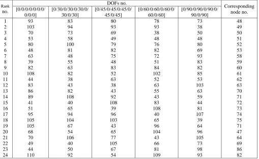
The resulting cumulative damage location plot in Fig.10.from which it can be the effect of noise is again random and negligible put there are now peaks of various magnitudes. These peaks of CDLP are ranked in order and illustrate (in Table.3).
ISSN(Online): 2319-8753 ISSN (Print): 2347-6710
I
nternational
J
ournal of
I
nnovative
R
esearch in
S
cience,
E
ngineering and
T
echnology
(A High Impact Factor, Monthly, Peer Reviewed Journal)
Visit: www.ijirset.com
Vol. 8, Issue 10, October 2019
DOFs at nodes 62 and 61 that are shared with element no. 44,45,46,47 and elements no 57,56,55,54 respectively would have even been far much larger. Thus it can be seen that DOFs in the immediate neighborhood of an element containing damage are also slightly affected.
0 15 30 45 60 75 90 105 120
0 30 60 90 120
2D Cumulative Damage Location Vector Plot for [0/0/0/0/0/0/0/0/0/0]
Degree Of Freedom (DOF)s
N
/m
0 15 30 45 60 75 90 105 120
0 30 60 90 120
2D Cumulative Damage Location Vector Plot for [0/30/0/30/0/30/0/30/0/30]
Degree Of Freedom (DOF)s
N
/m
0 15 30 45 60 75 90 105 120
0 30 60 90
1202D Cumulative Damage Location Vector Plot for [0/45/0/45/0/45/0/45/0/45]
N
/m
Degree Of Freedom (DOF)s
0 15 30 45 60 75 90 105 120
0 30 60 90 120
2D Cumulative Damage Location Vector for [0/60/0/60/0/60/0/60/0/60]
Degree Of Freedom (DOF)s
N
ISSN(Online): 2319-8753 ISSN (Print): 2347-6710
I
nternational
J
ournal of
I
nnovative
R
esearch in
S
cience,
E
ngineering and
T
echnology
(A High Impact Factor, Monthly, Peer Reviewed Journal)
Visit: www.ijirset.com
Vol. 8, Issue 10, October 2019
0 15 30 45 60 75 90 105 120
0 30 60 90
120 2D Cumulative Damage Location Vector Plot for [0/90/0/90/0/90/0/90/0/90]
Degree Of Freedom (DOF)s
N
/m
Fig.10 Lateral cumulative damage location plot using experimental FRF data for plate damage case B for various types of staking sequences. Table 3Ranking of DOFs from 2D CDLPfor plate damage cases A and B
ISSN(Online): 2319-8753 ISSN (Print): 2347-6710
I
nternational
J
ournal of
I
nnovative
R
esearch in
S
cience,
E
ngineering and
T
echnology
(A High Impact Factor, Monthly, Peer Reviewed Journal)
Visit: www.ijirset.com
Vol. 8, Issue 10, October 2019
VI. CONCLUSIONS
This paper aims to assess both theoretically and experimentally, damage detection using DLV's. The method is first studied theoretically on a thin plate structure suing simulated damage. The method is then tested experimentally on a free-free plate provided with several damage cases using Mechanical exciter tests. The method is improved through the use of FRFs of the intact structure obtained both numerically and experimentally in an attempt to overcome difficulties imposed by initial damage and noise. Based on the analytical and experimental assessment that was performed using the DLV algorithm, the following can be concluded:
1-The DLV method could detect damage location successfully both theoretically and experimentally. 2-The DLV can identify single cracks damage locations.
3-Damage identification based on DLV can accurately determine the extent of the damage from natural frequency and mode vector line drive.
4-Frequency response function (FRF) of the intact structure obtained numerically and experimentally, the DLV method could overcome difficulties imposed by initial damage and noise to detect and localize the damage experimentally. 5-The position of nodes and antinodes are shifted for cracked composite plates compared with plain ones.
REFERENCES
[1] A. Choudhury, ʻʻDamage detection in structures using measured frequency response function data,ʼʼ 1996.
[2] D. Tran and J. He, ʻʻStructural damage detection in a simple cantilever plate,ʼʼ in Proceedings of the 16th IMAC, Santa Barbara, February 2– 5,pp. 369-374,1998.
[3] S. Alampalli, G. Fu and Ew. Dillon, ʻʻ Signal versus noise in damage detection by experimental modal analysis,ʼʼ ASCE Journal of Structural Engineering,pp. 237–45, 1997.
[4] W. Ren and G. Roeck, ʻʻStructural damage identification using modal data I: simulation verification,ʼʼ ASCE Journal of Structural Engineering, pp.87–96, 2002.
[5] H. Hao and Y. Xia, ʻʻVibration-based damage detection of structures by genetic algorithm,ʼʼ ASCE Journal of Computing in Civil Engineering, Vol. 16(3):222-9, 2002.
[6] Z.Sun and C. Chang, ʻʻStructural damage assessment based on wavelet packet transform,ʼʼ ASCE Journal of Structural Engineering, pp.1354– 61, 2002.
[7] J. He and Z. Fu, ʻʻModalanalysis,ʼʼ Oxford: Butterworth Heinemann 2001.
[8] D. Huynh, J. He and D.Tran, ʻʻDamage location vector: A non-destructive structural damage detection technique,ʼʼ Computers and Structures, Vol. 83, pp. 2353–2367, 2005.
[9] H. Monajemi, A. Razak and Z Ismail,ʻʻDamage detection in frame structures using damage locating vectors,ʼʼ Measurement, Vol. 46, PP.3541– 3548, 2013.
[10] Z.Yang, Z Yu and H Sun, On the cross correlation function amplitude vector and its application to structural damage detection,ʼʼ Mechanical Systems and Signal Processing, Vol. 21, PP.2918–2932, 2007.
[11] S. Doebling, C. Farrar, M. Prime and D. Shevitz, ʻʻDamage identification and health monitoring of structural and and mechanical systems from changes in their vibration characteristics,ʼʼ a literature review, Los Alamos National Laboratory Report LA-13070-MS, April 1996.
[12] M. Kayed, M. Arafa and S. Megahed, “Vibration -Based Damage Detection in Plates Using Damage Location Vectors,” Proceedings of the ASME International Mechanical Engineering Congress & Exposition IMECE, Denver, Colorado, USA, Paper, IMECE2011-65117, November,2011.
[13] Y. Lee and M. Chung, ʻʻA study on crack detection using Eigen frequency test data,ʼʼ computers &structures,Vol. 77 (3), PP.327-342, 2002. [14] J. Kim and N. Stubbs, ʻʻCrack detection in beam-type structures using frequency data,ʼʼ journal of sound and vibration, Vol. 259, PP.145-160,
2003.
[15] M. Saada, M. Arfa and A. nassef, ʻʻFinite Element model Updating Approach to damage Identification in Beams Using Particle Swarm Optimization,ʼʼ computer and information in engineering conference, Brooklyn, New York USA Vol. 1, PP.521-30, 2008.
[16] D. Agarwalla and D. Parhi, ʻʻEffect of Crack on Modal Parameters of a Cantilever Beam Subjected to Vibration,ʼʼProcedia Engineering, Vol. 51, PP. 665-669, 2013.
[17] S. Hassiotis, ʻʻIdentification of damage using natural frequencies and Markov parameters,ʼʼ Computers and structures, Vol.74, pp.365-73,2000. [18] D. Maitithy and R. Tripathy,ʻʻDamage assessment of structures from changes in natural frequencies using genetic algorithm,ʼʼ Structural
Engineering and Mechanics, Vol.19, PP.21-42, 2005.
[19] P. Pawar and R. Ganguli, ʻʻMatrix crack detection in thin-walled composite beam using genetic fuzzy system,ʼʼ journal of Intelligent Material Systems and Structures, Vol.16, PP.395-409, 2005.
ISSN(Online): 2319-8753 ISSN (Print): 2347-6710
I
nternational
J
ournal of
I
nnovative
R
esearch in
S
cience,
E
ngineering and
T
echnology
(A High Impact Factor, Monthly, Peer Reviewed Journal)
Visit: www.ijirset.com
Vol. 8, Issue 10, October 2019
[21] Y.Z. Fu, Z.R. Lu and J.K. Liu,ʻʻ Damage identification in plates using finite element model updating in time domain,ʼʼ Journal of Sound and Vibration, Vol 332, pp. 7018–7032, 2013.
[22] L. Daryl, ʻʻFirst Course Course in the Finite Element Method,ʼʼ ,fourthed,Wisconsin, 2007.
[23] D. Bernal, ʻʻDamage localization from the null space of changes in the transfer matrix,ʼʼ AIAA J, Vol. 45, pp. 374-381,2007.
[24] A. Kaushik, B. Sundaram, S. Parivallal and K. Ravisankar,ʻʻ Numerical Studies on the Damage Locating Vector Approach for Damage Detection using Static Load Data,ʼʼ 1st International Conference on Structural Integrity, ICONS, 2014.