ABSTRACT
LOPATIN, SERGEI. Atomic and Electronic Structure of Interfaces in Materials Systems for Future Semiconductor Devices. (Under the direction of Gerd Duscher.)
Because of the intrinsic limits of the Si/SiO2 based industry, there is a great trend towards
the monolithic integration of new materials into already well developed silicon technology. Some of those materials are GaAs (which is widely used for production of light-emitting diodes, solar cells, and high-power transistors), Ge (which forms Si/SiGe heterostructures and thus opens the way for carrier mobility enhancement and band structure engineering), HfO2 and Al2O3 (which are among the most promising materials for urgently required
substitution of SiO2 as a high-κ dielectric). These materials can be used for the fabrication of
prototypes of spherical aberration correctors, enabling to achieve the highest resolution currently available both in space and energy. The above combination of experimental and theoretical methods was applied to study interfaces between Si/GaAs, Si/Ge, Ge/SiO2,
Si/HfO2 and Si/Al2O3. All these materials interfaces play an important role in the
contemporary semiconductor industry, have high potential for future applications and, thus, are currently under detailed investigation. As the result of the present research, a new dislocation configuration at the Si/GaAs interface was reported for the first time and the atomic structure model of this dislocation has been revealed. The influence of this dislocation structure on the electrical properties of the Si/GaAs interface was analyzed. Also, the transition from Si to GaAs and from Si to Ge at corresponding interfaces was described with atomic precision, focusing on the changing electrical properties of Si. For the first time, the interface between Ge and SiO2 was shown to have “ideal” characteristics (chemical
abruptness and sharpness). This indicates the potential, both for a more successful use of Ge in high-speed devices (it is shown to form an excellent interface with oxides) and for advances in interface engineering to enhance performance in electronic devices. The features of Si/HfO2 and Si/Al2O3 interfaces, namely the distribution and bonding of Si and Hf across
the interface, and the formation of charged SiO2 islands at the Si/Al2O3 interface were also
ATOMIC AND ELECTRONIC STRUCTURE OF INTERFACES
IN MATERIALS SYSTEMS FOR FUTURE SEMICONDUCTOR DEVICES
by
SERGEI LOPATIN
A dissertation submitted to the Graduate Faculty of North Carolina State University
in partial fulfillment of the requirements for the Degree of
Doctor of Philosophy
MATERIALS SCIENCE AND ENGINEERING
Raleigh 2003
APPROVED BY:
BIOGRAPHY
Sergei Lopatin was born November 23, 1974 in Borisov, Republic of Belarus. He received his elementary and secondary education at high school #137 of the hero-city Minsk,
Belarus, graduating with honors in 1991. He then began his college career joining Belarus State University, where he was a student at the Department of Physics, and where he received his Master degree in Physics graduating with honors in July, 1996.
He proceeded to continue his graduate education joining the Materials Science and Engineering Department at North Carolina State University. He enrolled in the Graduate
ACKNOWLEDGEMENTS
First of all I would like to express my sincere thanks to Dr. Gerd Duscher for the constant support and guidance he provided me throughout the unfortunately very few years our paths
have crossed. I would like to thank him for offering me an incredible opportunity to be part of his research and for providing me an access to the state-of-the-art of up-to-date
experimental and theoretical methods and tools for the exploration of nature. Also many thanks to Dr. Duscher’s wife Krista for her help in preparation materials for publication.
I sincerely appreciate Dr. Alex Kvit for his help in introducing me to Transmission
Electron Microscopy and sample preparation techniques. I also appreciate the assistance and collaboration of Dr. Wolfgang Windl from Ohio State University in the field of computer
simulations.
I would like to extend my deep appreciation to Dr. Steven Pennycook for the opportunity to be in his research group in Oak Ridge National Lab, and to Dr. Matthew Chisholm and Dr.
Andrew Lupini from this group for enlightening discussions.
Also I would like to thank members of my advisory committee Dr. Mark Johnson, Dr. Michael Rigsbee, Dr. George Rozgonyi, and Dr. Christopher Roland for their interest in my
research.
Finally I must offer my warmest thanks to my parents for their eternal support and to my
TABLE OF CONTENTS
LIST OF TABLES ...vi
LIST OF FIGURES ...vii
1. INTRODUCTION ... 1
2. LITERATURE REVIEW ... 3
2.1. Si/SiO2 Interface ... 3
2.2. Si/GaAs Interface... 7
2.3. Si/Ge Interface ... 15
2.4. Ge/Oxide Interface... 21
2.5. Si and High-κ Dielectrics ... 22
2.5.1.Permittivity and Bandgap...24
2.5.2.Thermodynamic Stability on Si ...27
2.5.3.Si/HfO2 Interface ...30
2.5.4.Si/Al2O3 Interface ...32
3. METHODS AND TOOLS ... 36
3.1. Aberration Corrected TEM/STEM ... 36
3.2. Z-contrast Imaging... 41
3.3. Electron Energy Loss Spectroscopy ... 46
3.4. Density Functional Theory ... 52
4. RESULTS AND DISCUSSIONS... 58
4.1. Si/GaAs Interface... 58
4.1.1.Z-contrast Imaging...58
4.1.2.EELS...61
4.1.3.Calculations ...62
4.1.4.Discussion ...66
4.1.5.Summary...69
4.2. Si/Ge Interface ... 70
4.2.1.Z-contrast Imaging...70
4.2.2.EELS...72
4.2.3.Discussion ...73
4.2.4.Summary...74
4.3. Ge/SiO2 Interface... 75
4.3.1.Z-contrast Imaging...75
4.3.2.EELS...77
4.3.3.Calculations ...79
4.3.4.Discussion ...81
4.3.5.Summary...83
4.4. Si/HfO2 Interface ... 84
4.4.1.Z-contrast Imaging...85
4.4.2.EELS...88
4.4.3.Discussion ...90
4.4.4.Summary...91
4.5. Si/Al2O3 Interface ... 92
4.5.2.EELS...93
4.5.3.Discussion ...95
4.5.4.Summary...97
5. CONCLUSIONS... 98
LIST OF TABLES
Table 1. Comparison of some basic materials properties of Si and GaAs at room temperature
(from [9]). 7
Table 2. Room-temperature bulk mobilities of electrons and holes in unstrained, undoped Si and Ge
LIST OF FIGURES
Figure 1. Examples of Si-SiO2-Si superstructures with one (a) and two (b) oxide layers. The left
panels are abrupt interfaces; the right panels have suboxide bonding (after [7]). 6 Figure 2. Band offsets for high-κ dielectrics on Si (from [46]). 25 Figure 3. Dielectric constant κ versus band gap for candidate gate oxides (from [46]). 26 Figure 4. Dielectric constant κ versus optical bandgap EG of alternative gate dielectrics that are
likely to be stable in contact with silicon (from [54]). 29 Figure 5. Spherical aberration in the lens causes wavefronts from a point object P to be
spherically distorted (after [70]). 36
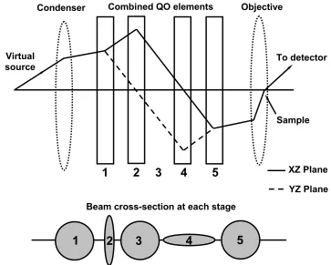
Figure 6. Principle scheme of the quadrupole-octupole correction of spherical aberration in
STEM. 38
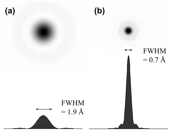
Figure 7. The intensity profile of the electron beam of (a) non-corrected and (b) Cs corrected
VG HB501 STEM. 39
Figure 8. The results of imaging of a Ge0.3Si0.7 alloy without aberration correction (a) and (c),
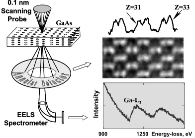
and with aberration correction (b) and (d) (from [79]). 40 Figure 9. Schematics of atomic resolution Z-contrast imaging and EELS. 42 Figure 10. Schematic representation of the experimental probe and the object function
convolution [from 84]. 44
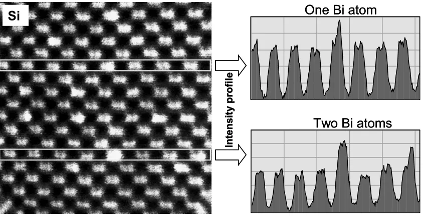
Figure 11. Imaging of single Bi atoms in Si(110) (by A. Lupini, VG HB501UX with Nion
Aberration Corrector, 100 kV). 46
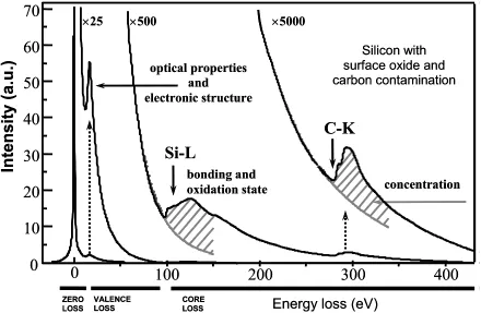
Figure 12. EELS of Si, revealing different information at different energy scales. (Courtesy of
Gerd Duscher) 47
Figure 13. The origin of Si-L2,3 ionization edge in EELS. 49 Figure 14. Z-contrast image and EELS of the Si/SiO2 interface. 51 Figure 15. Calculated Si-L2,3 edges at the Si/SiO2 interface with respect to an abrupt interface
model (on the left) and a sub-oxide interface model (on the right). (Courtesy of Gerd
Duscher) 56
Figure 16. Z-contrast image of Si/GaAs interface. 59 Figure 17. Z-contrast image of a 60° dislocation (a) and the structural model of the dislocation
core (b). 59
Figure 18. Z-contrast image of a reconstructed 90° dislocation (a) and the structural model of the
dislocation core (b). 60
Figure 19. Z-contrast image of a non-reconstructed 90° dislocation (a) and the structural model
of the dislocation core (b). 60
Figure 20. EELS of the Si-L2,3 edge from the planar Si/GaAs interface (no dislocations). 61 Figure 21. Comparison of Si-L2,3 edges obtained from bulk Si and dislocation cores at the
Si/GaAs interface. 62
Figure 23. Calculated DOS of Si atoms (a, b, c) with respect to their position in the relaxed Si/GaAs super-cell (d) with reconstructed and non-reconstructed 90° dislocations. The
dotted line corresponds to bulk Si. 65
Figure 24. Calculated DOS of As atoms (a, b, c) with respect to their position in the relaxed Si/GaAs super-cell (d) with reconstructed and non-reconstructed 90° dislocation. The
dotted line corresponds to bulk As. 66
Figure 25. The relaxed core of a threading edge dislocation in GaN from [99]. 67 Figure 26. contrast image of a Ge film on a Si substrate (a) and intensity profile of the
Z-contrast image along one atomic plane across the interface as indicated in the
micrograph (b). 71
Figure 27. Stacking fault in the Si/Ge system. 72 Figure 28. The distribution of the Si-L2,3 ionization edges across the Si/Ge interface. 73 Figure 29. Z-contrast image of a Ge film on a Si substrate covered by SiO2 (a); intensity profile of
the Z-contrast image along one atomic plane across the interface as indicated in the
micrograph (b). 75
Figure 30. Low magnification Z-contrast image of Ge film on a Si substrate covered by SiO2. 76 Figure 31. Line-scan EELS of Si-L2,3 ionization edge across (a) the Si/SiO2 interface, (b) the
Ge/SiO2 interface. 77
Figure 32. The thickness profile of the studied Si/Ge/SiO2 sample. 78 Figure 33. The model, deduced from experimental results, for the atomic structure of the
Ge/SiO2 interface. 81
Figure 34. Z-contrast images of Si substrate with HfO2 film and corresponding intensity profile. 85 Figure 35. Z-contrast images (Fourier filtered) of the control and the test samples showing
different roughness of the Si/HfO2 interface. 86 Figure 36. Z-contrast images of control and test samples showing crystallization of the HfO2 film. 87 Figure 37. Z-contrast images of the Si/HfO2 interface from Nemanich group samples, showing (a)
steps on the Si surface, and (b) re-crystallization of the HfO2 film. 87 Figure 38. Line-scan EELS of the Si-L2,3 ionization edge across the Si/HfO2 interface of the
control sample. 88
Figure 39. Line-scan EELS of the Si-L2,3 ionization edge across the Si/HfO2 interface of the
1. INTRODUCTION
At present time the more and more increasing demands of the technology and communications market push the manufacturers of optoelectronic devices towards further reduction of the dimensions of the active device in the integrated circuits to obtain greater functionality and performance at lower cost. Traditional Si-based semiconductor technology has almost exhausted its own resources and future development is impossible without the introduction of other materials, such as GaAs (which is widely used for production of light-emitting diodes, solar cells, and high-power transistors), Ge (which forms Si/SiGe heterostructures and thus opens the way for carrier mobility enhancement and band structure
engineering) and urgently required high-κ dielectrics for substitution of SiO2 as an insulator.
Moreover, having continued for several decades, downscaling reaches the limit, where a single device dimension approaches the size of an atom. At such a level of miniaturization, the characteristics and behavior of resultant optoelectronic devices are controlled not by the properties of the bulk material, but rather by the interface between two materials. Thus, the characterization of precise atomic arrangements at different interfaces is urgently required for the understanding of the structure-property relationships.
While characterizing interfaces between materials, different issues can be addressed such as coherency, the existence of surface states and dangling bonds, chemical abruptness, problems with interdiffusion, thermal stability, etc. Without any doubt, the Si/SiO2 interface
has been the most studied and characterized from different point of views, because its excellent and so far unique properties determined the growth of the semiconductor industry
bench mark or reference point to compare or contrast with the properties of other interfaces investigated here. Hence, the present research is organized as follows.
The “Literature Review” section provides a summary of today’s knowledge of Si/SiO2
interface properties and its main advantages. The Si/SiO2 interface is the benchmark that has
to be met for any new materials system for almost every application. It is followed by the detailed consideration of current status of scientific research in the field of semiconductor and dielectric materials such as GaAs, Ge, HfO2, and Al2O3, i.e. materials studied here.
The combination of scanning transmission electron microscopy techniques (Z-contrast imaging and electron energy-loss spectroscopy) and calculations based on the density functional theory is selected for the characterization of structure-properties relationships of Si/GaAs, Si/Ge, Ge/SiO2, Si/HfO2 and Si/Al2O3 interfaces. The description of those
experimental and theoretical methods is given in the “Methods and Tools” section. Specific attention is concentrated on the advantages of spherical aberration corrector, the development of which pushed the resolution of electron microscopy to the truly atomic level.
The choice of materials (interfaces) is stipulated by the attempt to consider different sides of possible transitions from traditional Si and SiO2 to other materials, i.e. first to consider
structure-property relationships of Si as a crystalline semiconductor in contact with other crystalline semiconductors (Si/GaAs and Si/Ge), then to focus the attention on the connection of amorphous SiO2 with crystalline materials (Ge/SiO2), and finally, to switch to the
interfaces between Si and amorphous materials (Si/HfO2 and Si/Al2O3). Such an approach
determined the sequence of the results presented in “Results and Discussions”.
2. LITERATURE REVIEW
2.1. Si/SiO2 Interface
The first working silicon transistor was built by Gordon Teal in 1954 when sufficiently
pure silicon could be produced [1]. The next big jump in transistor evolution came with the development of the metal oxide semiconductor field effect transistor (MOSFET) in 1960 by
John Atalla [1]. The silicon based MOSFET became the most common transistor in our days and the share of silicon devices in the world-wide market reaches an overwhelming 95%.
The tremendous growth of the Si-based industry over the last several decades is directly
related to the combination of an easily available semiconductor and an excellent natural oxide, SiO2, which serves as an insulator and as a protecting passivation layer. The
combination Si/SiO2 is the basis for the MOSFET that can be integrated monolithically in
enormous quantities in a very large-scale integration (VLSI) technology [2].
There are a number of factors determining the excellent chemical, mechanical and
electrical properties of the Si/SiO2 interface. First among these are the flexibility of the
amorphous SiO2 network and the high potential for glass formation. When oxidized, Si forms
four bonds to oxygen atoms. The Si–O bond is about 50% ionic and the ionicity is below a
critical value, so the bond is qualitatively covalent and directional [3]. The oxygen atoms are two-fold coordinated, with a large bond angle and a weak bond-bending force constant. The
low average coordination and the “floppiness” of the oxygen site mean that SiO2 is a very
good glass-former [4].
As a result, in terms of charged defects the Si/SiO2 interface is so far unique. Even
enough to minimize the number of interface dangling bonds. The same works not only for the interface but for the oxide layer itself.
In general, defects in the oxide are critical to its performance as a gate dielectric. Defects
in SiO2 are well understood. As a covalent solid, its defects are (1) dangling bonds on Si and
O atoms and (2) the oxygen vacancy, known as the E′ center. Si dangling bonds are
undesirable because they form states in the middle of the Si bandgap that can trap charge. Si
dangling bonds in the SiO2 can trap charge and can also cause soft (reversible) breakdown.
However, the defect density in SiO2 is very small, primarily because its large cohesive
energy makes defects energetically costly and also because the flexibility of its network
allows them to reconstruct. More over, there is an additional method for removing dangling bond defects, i.e. the injection of hydrogen. Hydrogen atoms diffuse rapidly in SiO2 and can
passivate any dangling bonds at the Si/SiO2 interface or the SiO2 layer, and so remove these
states in the gap:
≡Si′ + H′ → ≡Si–H.
The density difference of Si and SiO2 due to the volume expansion creates certain
difficulties in devising atomic models of the interface. Despite extensive work, neither the atomic-scale structure nor the composition (or gradient) in the transition region are well
understood – there has been no universally accepted “conventional” model [5]. But the existing crystalline models suffice to show the main issues. There are more dangling bonds on the ideal Si surface than on a SiO2 surface because of the density difference. To join a Si
lattice to a SiO2 network, some Si bonds on the Si side must be tied off to each other. This
bridging oxygens between the pairs. The remaining Si dangling bonds are then connected to oxygen dangling bonds on the SiO2 side to give a defect-free interface.
Also, different models say that between a crystalline Si substrate and an amorphous oxide
overlayer there is a transition region consisting of a mixture of Si in various oxidation states: Si1+, Si2+, Si3+, where Si has one, two, and thee first nearest-neighbor oxygen atoms,
respectively. Six+ (x=1,2,3) is also frequently referred to as suboxide. Together with dangling bonds those suboxides introduce energy levels in the bandgap, thus degrading the quality of a dielectric. Recent experiments of Muller et al. [6] demonstrated that in the best case it takes
at least 2 monolayers of mixed suboxide for the transition from the Si substrate to the stoichiometric SiO2.
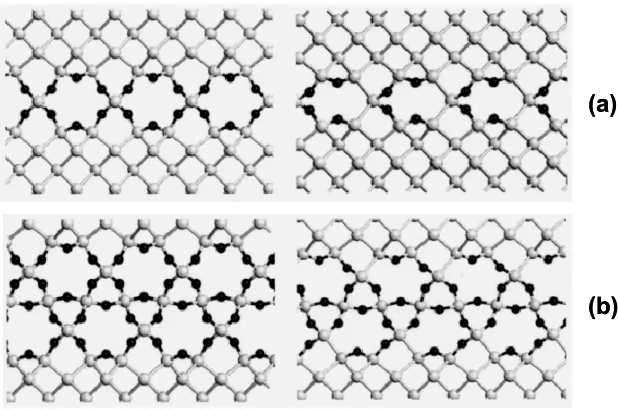
Buczko et al. [7] addressed the mechanisms that control abruptness of the Si/SiO2
interfaces by considering the energetics of different possible structures produced by “theoretical” layer-by-layer deposition of SiO2 onto Si (see Figure 1). In the case of the Si
(001) surface, a set of judiciously chosen ab initio calculations suggest that abrupt interfaces (those with one layer of only Si2+ oxidation states directly followed by Si4+, i.e. stoichiometric SiO2) generally have lower energy. The origin of this result can be traced to
the softness of the Si-O-SiO2 angle and the particular geometry of this surface, which
imposes order in the interface layer. These effects make suboxide bonds energetically costly,
thus setting the stage for potentially perfect interfaces.
However it is noted in [7], that the entropic considerations that normally introduce defects (in this case, suboxide bonds) to lower the free energy at finite temperatures must be
two types of domains. It is these domain boundaries, plus entropy effects within domains, that are the likely cause of the observed suboxide [6] and dangling bonds [8].
(a)
(b) (a)
(b)
Figure 1. Examples of Si-SiO2-Si superstructures with one (a) and two (b) oxide layers. The left panels are
abrupt interfaces; the right panels have suboxide bonding (after [7]).
So there are natural limitations for the minimum thickness of SiO2 layer to serve as a gate
dielectric. While those limits are not reached, the use of amorphous, thermally grown SiO2 as
a gate dielectric in complimentary-metal-oxide-semiconductor (CMOS) processing offers
several key advantages:
• The very high SiO2 bandgap of nearly 9 eV, and a Si/SiO2 potential barrier for electrons
(conduction band offset) of more than 3 eV, making SiO2 an excellent insulator (resistivity ≥
1015Ω cm) even when the layer thickness is reduced to a few nanometers.
• Thermal and chemical stability, needed for the high-temperature processing and mass
production of integrated circuits.
• The high quality of the Si/SiO2 interface. In modern CMOS processing, defect charge
~1010/cm2 eV. This, in part, results from post-annealing in a hydrogen-containing ambient, which passivates dangling bonds. This excellent interface allows for high mobility of the carriers in the MOSFET channel and high device performance.
• Low charge trapping and splendid reliability.
All these properties of Si/SiO2 interfaces combined together are the key to the fabrication
of more than 40 million transistors with identical electrical behavior on a single Si chip as is
commercially available in our days.
2.2. Si/GaAs Interface
Compound semiconductor materials and devices have been the topic of research for more
than 30 years by a large number of engineers and scientists in a large number of varied institutes. Gallium arsenide (GaAs) is a III-V compound semiconductor and probably the
second most common semiconductor material after Si. It has some unique properties that make it ideal for use in applications that silicon is ill-suited for.
Table 1. Comparison of some basic materials properties of Si and GaAs at room temperature (from [9]).
Silicon Gallium Arsenide
Lattice constant (Å) 5.43 5.65
Energy gap (eV) 1.12 1.42
Band gap type Indirect Direct
Electrons 1450 8500
Bulk mobility
(cm2 V-1 s-1) Holes 505 400
Thermal conductivity (W cm-1°C-1)
Gallium arsenide forms a face centered cubic lattice with a basis of one gallium and one arsenic atom in what is called a zincblende structure. Table 1 compares some fundamental properties of GaAs and Si [9]. The energy difference of 0.3 eV in the bandgap has a profound effect on the intrinsic properties of these semiconductors. First of all is the high isolation and low parasitics enjoyed by GaAs devices.
The direct nature of the energy gap in GaAs, in contrast to Si, is the origin of the highly favorable optical transition probabilities. This single factor explains the existence of the highly efficient photoluminescence properties of GaAs, as well as justifying its suitability for fabrication of light emitting diodes and lasers.
The charge carrier mobility of GaAs is probably the most advertised parameter of this
semiconductor. The charge carrier mobility µ is itself the most important transport parameter
of a semiconductor material. It describes the linear relation between the average carrier drift velocity v and an external electrical field E in the low-field limit (and in the absence of external magnetic fields):
E
v=µ⋅ .
The electron mobility in GaAs is significantly higher than that in Si, and it is this parameter which allows the higher speed performance of GaAs devices over Si. However the hole mobility in GaAs is significantly lower than the electron mobility and this disparity leads to a less favorable situation for the possibility of implementing complimentary device structure for circuits in GaAs.
High performance applications of GaAs are found ranging from wireless communications and digital synthesis, through high speed computing. One of the earliest reports of a high performance GaAs IC was recorded in 1974 [10], which referred to Schottky metal-semiconductor field effect transistors (MESFETs) fabricated on semi-insulating (SI) GaAs substrate. Today the GaAs MESFET is the fundamental block of GaAs IC technology. However, other III-V technologies have also been developed, and offer different combinations of advantages and disadvantages. The junction field effect transistor (JFET) is very closely related to the MESFET. The major difference is that JFET uses a pn-junction rather than a Schottky barrier as a control element. The use of a pn-junction results in a larger barrier height, almost as large as the energy gap. JFET technology has been demonstrated to be capable of fabricating low power/high density random access memory (RAM) with high radiation tolerance [11], as well as high density/high speed LSI gate arrays [12].
have a very high transconductance and the potential for very high speed operations (analog signal processing, analog-to-digital conversion, microwave power amplification).
There are several other III-V device technologies which are based on epitaxial materials.
These include: resonant tunneling diodes (RTD), hot electron transistors (HET), permeable base transistors (PBT), semiconductor-insulator-semiconductor FETs (SISFET), the
metal-insulator-semiconductor FETs (MISFET), and pseudomorphic HEMTs (P-HEMT). These are all epitaxial devices and, thus, they have a potential to be fabricated in the (III-V)-on-Si configuration.
The epitaxy of gallium arsenide on silicon has a number of objectives [14]. GaAs may serve as a material system by itself, for example GaAs/AlGaAs lasers and photodetectors can be used for interchip communication in Ultra Large Scale Integrated (ULSI) circuit systems. On the other hand, GaAs may serve as a base system (substrate) for integrating other compound semiconductors to silicon, i.e. other compound semiconductors can be grown on Si substrates using a GaAs buffer layer. In this way, for instance, InSb based infra-red detectors can be monolithically integrated to the Si based charge coupled devices (CCD) image processing systems.
Besides monolithic integration, the GaAs epitaxy on Si has many other advantages. The important ones are as follows.
• Large diameter wafer production requires a highly developed technology. GaAs on
Si allows for exploitation of the mature Si wafer technology to produce large diameter GaAs epilayers that can just as effectively function as “GaAs substrates”.
• Since Si has a superior thermal conductivity and GaAs has better electronic
properties of the constituents to yield a highly optimized overall system. As a result, GaAs circuits fabricated on Si substrate can exhibit higher resistance to thermal burnout and runaway than those fabricated on GaAs substrate.
• Silicon also exhibits superior mechanical properties. To achieve the same
mechanical strength as GaAs on Si, the GaAs on GaAs requires thicker substrate. Thicker
substrates increase the cost and weight, and may require new processing equipment to
accommodate the increase in thickness. Especially for space-based applications like solar
cells on satellites, the GaAs on Si is a better choice than GaAs on “thicker” GaAs.
• Si wafer cost practically a small fraction of GaAs wafer. The process of epilayer
growth is expensive, but for structures that inherently require epitaxial growth, i.e.
heterostructures, MODFETs, quantum wells, etc., the extra effort involved in the growth of
GaAs on Si is insignificant.
As a result of the impressive progress in epitaxial growth of GaAs on Si, all the main
electrical and optical GaAs devices and GaAs buffered devices grown on Si substrate have been successfully demonstrated and their properties have been compared with the same devices grown on GaAs substrate. Majority-carrier devices have demonstrated properties
equivalent to their counterparts on GaAs. For example, FETs, being majority-carrier devices, are less sensitive to crystal quality then lasers and other minority-carrier devices. Consequently, FETs were the first devices to be realized in GaAs on Si. The first report of
the fabrication of GaAs MESFETs on Si was from Choi et al. through the use of Ge intermediate layers [15]. Shortly thereafter the same group reported MESFETs directly
comparable with MESFETs on GaAs substrates, the noise performance was considerably degraded due to the presence of structural defects.
The issue of defects at the Si/GaAs interface (first of all dislocations) is even more
serious for minority charge carrier devises such as bipolar transistors, light emitting diodes, detectors and solar cells. For example, since Si has a density less than a half of GaAs and
may be used as a light-weight substrate, a single-crystal cascade with Si as the bottom cell and a III-V alloy on the top looks promising for concentrator solar systems, especially for those destined for space-based operation. Such cells, with each material absorbing in a
different portion of the solar spectrum, could achieve conversion efficiencies as high as 36% [17]. However, recombination losses at dislocations are the limiting factor in determining the
performance of Si/GaAs solar cells. The first Si/GaAs solar cells yielded conversion efficiencies of 12 % (AM1) [18], but there are indications [19], that the reduction of dislocation density may significantly improve Si/GaAs solar cells characteristics.
In general, the epitaxial growth of GaAs on Si is not without inherent problems. The important ones among the many are growth initiation of a polar (GaAs) semiconductor on a non-polar one (Si), the 4.1% lattice mismatch between silicon and gallium arsenide (Table 1),
and the 60% mismatch in thermal expansion coefficient. The quality of the surface is also critical for epitaxial growth.
step are similar to the surface atoms and have dangling bonds; some of these dangling bonds may rebond at the step edge. The rebonding of edge dangling bonds influences the formation energy and stability of steps and can be altered by high temperature or chemical treatment.
The presence of monolayer high surface steps can lead to antiphase domains in GaAs on Si. The crystalline structures of Si and GaAs consist of two interpenetrating face centered cubic Bravais lattices. In the case of Si, the two f.c.c. are the same. It is invariant of rotation
of π/2 and [011] and [01 ] direction are equivalent. In the case of GaAs, one f.c.c. lattice is 1
occupied by Ga and the other by As, and the [011] and [ 101 ] directions are not equivalent.
This distinction is very visible in the (100) planes of GaAs which consist of alternating layers of Ga and As. When GaAs is grown on GaAs substrate, the Ga and As atoms experience no ambiguity in choosing lattice sites, but that is not the case when epilayers of GaAs are grown on Si (100). The lattice sites on the (100) planes are indistinguishable and so there are no preferential nucleation sites for Ga and As. To make matters worse, silicon bonds well to both Ga and As. If the growth is started with simultaneous exposure to gallium and arsenic molecular beams, gallium may form the initial layer on some areas of the substrate and arsenic on the rest of the surface, i.e. the first monolayer is part Ga and part As on the Si substrate. This results in As-As or Ga-Ga bond boundaries which are called anti-phase boundaries (APBs). The formation of APBs is aided by monolayer high steps. Anti-phase boundaries are charged structural defects. The epilayer containing APBs may behave as a
More serious problem of manufacturing GaAs devices integrated in silicon technology is associated with the lattice mismatch of 4.1% between GaAs and Si. This mismatch leads to the creation of a large number of interfacial dislocations (misfit dislocations). Dislocation densities of the order of 106 cm-2 are generally observed at the GaAs/Si interface.
Dislocations affect the quality of the epilayer in several different ways. For instance, introducing dangling bonds, they form non-radiative recombination centers. The number of these centers can be even increased under intense photon fluxes, such as those in lasers. Another example is the increase in the ease of impurity diffusion and segregation along the line of dislocation threading; thus Si can diffuse from the substrate and cause autodoping in the epilayer.
Dislocations are often specified in terms of Burgers vectors. The commonly occurring dislocations in zincblende and diamond semiconductors can be classified in two different ways: (1) those whose Burgers vectors are parallel to the growth (Si/GaAs interface) plane and (2) others. The former is called a type I dislocation and the latter type II [21].
If the crystal growth direction is [001] and the dislocation line direction is [110], then
Burgers vectors [101]/2 and [011]/2 both form a 60° angle with the dislocation line (type II dislocations). These 60° dislocations may originate from the steps on the free surface [22]. These two dislocations may react to form a type I dislocation with a Burgers vector of [110]/2, which is perpendicular to the dislocation line (90° dislocation). The 90° dislocation relieves the strain energy more efficiently than other dislocations because it is aligned with the strain relaxation direction.
(111) plane for type II dislocation. The (111) planes are easy slip planes in GaAs. So type II dislocations can easily move up through the GaAs epilayer and reach the surface. Such a propagation of dislocations from the interface through the epilayer is called threading.
Besides causing impurity diffusion, threading lines also cause partial short circuiting of p-n junctions and degradation of optical and electrical properties of epilayers.
In the last few years, the dependence of interface dislocations on growth conditions and
post growth treatment has been investigated extensively and a number of promising techniques have been proposed for the reduction of dislocation densities and strain in hetero
epitaxially grown layers to achieve high performance devices on Si [23, 24, 25], and yet it remains a serious issue. It should be mentioned that the lattice mismatch between GaAs and another “popular” semiconductor material, namely Ge, is much lower that for Si, which may
benefit the combined integration of GaAs and Ge into Si technology. So it is the Ge to be discussed in the next section.
2.3. Si/Ge Interface
The properties of the Si/SiO2 material system make it ideally suited for digital
applications with a very high level of complexity. On the other hand, a variety of
fast-growing market segments, especially in the areas of millimeter-wave and optical communication, appear to be outside the scope covered by the electronic and optoelectronic
properties of Si. Therefore, in the last 30 years a substantial research and development effort has been dedicated to the development of alternative semiconductors with superior high-frequency behavior and optoelectronic functionality. For example, the properties of many
several device types are now available commercially. Prominent examples are quantum well transistors (often referred to as HEMTs (high-electron-mobility transistors) or MODFETs (modulation-doped field-effect transistors)) and quantum well lasers. Both exploit the band
offset of a heterostructure for the confinement of carriers in a quantum well defined by the energetically favorable material. HEMTs with high-frequency cut-off frequencies of several 100 GHz have been demonstrated, which are far beyond anything conceivable with Si
transistors.
However, although properly designed III–V heterostructures can excel in almost every category of electronic and optoelectronic properties, they completely lack a natural oxide or other insulator with the quality and versatility required for a very large-scale integration (VLSI) technology. The problems associated even with a moderate level of integration density are thus a fundamental drawback of III–V compound heterostructures, which will restrict the market volume that can be addressed by these materials in the near future.
The analysis of the benefits and limitations of the semiconductor systems presently employed for commercial devices may suggest that a combination of the Si/SiO2 system
(with its VLSI capability) and a heterostructure (enabling the design freedom of bandgap and band offset) could be a very powerful means for expanding the performance range of contemporary integrated circuits (ICs). For example, it has been known for many years that by adjusting the semiconductor bandgap, the bipolar device switching speed can be boosted.
As a straightforward step in that direction, the growth of GaAs and other III–V mixed semiconductors on Si substrates has been pursued for quite some time [14]. The successful
today's highest performance applications. Functionality improvement using these rather exotic materials, however, comes at a high price — cost and manufacturability. Moreover, the substantial lattice mismatch and anti-phase boundary formation in the III–V
heterostructure make this a troublesome combination of materials in terms of epitaxial growth and long-term stability of the devices. In this respect, the Si/Si1-xGex is a much better
suited heterosystem, because of “natural” matching of Si and Ge.
The existence of Ge was predicted by Russian chemists Mendeleev in 1871 as “Ekasilikon” and the element was found by Winkler, a professor of chemistry, in 1886 and
was given a name after the country of discovery (Germany). Ge is a silvery-white brittle semiconductor of the carbon group in the periodic table. It is stable in air and water and is unaffected by alkalis and most acids. Its physical properties are very similar to those of Si
which precedes it in the same group. Whereas Si is almost the most abundant element on earth, Ge is found only in trace amounts in some coals and ores. Pure Ge is produced by
reduction of the oxide and ultra high purity material is obtained by zone refining. It is this material that was used for the creation of the very first solid state amplifier, earning Bardeen, Brattain and Shockley the Nobel Prize in Physics in 1956 [1].
The structural and chemical properties of Ge and Si are very similar, which eases epitaxial growth and the application of standard Si technologies. Silicon and germanium are
the only group-IV elements that are completely miscible, i.e. they form a continuous series of solid substitutional solutions with gradually varying properties (such as resistivity) over the entire composition range. The elements and the random SixGe1-x alloys crystallize in the
bandgap in both Si (1.1 eV) and Ge (0.66 eV) is indirect, and remains so for all compositions in the SixGe1-x. Though the bandgap variation is strongly effected by strain in SixGe1-x
crystal, the band structure can be tuned within the relatively wide margins given by pure Si
and Ge by means of these alloys.
As mentioned in (2.2), the most important transport parameter of a semiconductor
material is the carrier mobility µ. The mobility µ is directly proportional to the transport
scattering time τand indirectly proportional to the effective mass m* of the respective carrier: *
/m
e τ
µ = ⋅ , where e is the electron charge.
Table 2. Room-temperature bulk mobilities of electrons and holes in unstrained, undoped Si and Ge (from [9]).
Silicon Germanium
Electrons 1450 3900
Bulk mobility
(cm2 V-1 s-1) Holes 505 1800
Within the limits of the wave-vector-independent relaxation time approximation, τ is the
sum of all reciprocal scattering times associated with the various scattering mechanisms. Thus the mobility is limited by the mechanism with the smallest scattering time. The main
scattering mechanisms in the elemental (nonpolar) semiconductors are scattering at acoustic and optical phonons (‘lattice scattering’), and scattering at ionized and neutral impurities [28]. In SixGe1-x crystals, random alloy scattering contributes as a fourth independent
mechanism. Strain may affect all scattering mechanisms.
The smaller effective mass of Ge [9] contributes to the significantly larger values of both
reference for the subsequent examples). The hole mobility of Ge is especially worth mentioning, since it is higher than in any of the III–V compounds, and matches the electron mobility of Si to within 20%.
At the present time Ge is a semiconductor material, industrially used for the large-scale production of various electronic devices, such as, for example Ge photocapacitive MIS infrared detectors [29], light emitting diodes [26], and for rather unknown applications such
as solar cells, that provide the electrical supply of telecommunication satellites [30]. Even the Ge-nanocrystal films deposited by the cluster-beam evaporation technique are attractive
materials for application to light emitting devices in future [31]. But it is the enhanced electron and hole mobilities and the possibility of the band structure tailoring in combination with Si, that attracts the most attention to Ge. The obvious advantages of Si/Si1-xGex
heterosystems were recognized at an early stage of heterostructure research, with the first report on the Si/SiGe superlattice appearing back in 1975 [32].
The enhancement of carrier mobility is one of the most attractive features derived from the band engineering utilizing Si/Si1-xGex heterostructures and it can open the way to
surpassing the limit of conventional Si MOSFETs. Especially, the hole mobility of Si-based
materials which limits the performance of complementary MOS type circuits is expected to be enhanced by the strain originating from the lattice mismatch in SiGe heterostructures.
Thus, for example, Irisawa et al. [33] reported that solid source molecular beam epitaxy was used for a successful growth of Si0.3Ge0.7/strained Ge channel/Si0.3Ge0.7 heterostructures with
ultrahigh hole mobility on Si (100) substrates. Suppression of parallel conduction, which
mobility up to 2100 cm2/V·s. Using this technique, p-type MOSFETs without parallel conduction are successfully fabricated and the peak effective hole mobility of 2700 cm2/V·s at RT was obtained, which is much higher than that of bulk Ge drift mobility [9]. The main
reason for large enhancements of the mobility are the very small effective mass of holes in the strained Ge (~0.01 of free electron mass) and the absence of alloy scattering which can be a dominant scattering mechanism in SiGe alloy.
Since SiGe allows a change of the bandgap by varying the Ge content of the alloy, SiGe also seems to be a promising material for a perfect spectral match of a photocell to a given
thermophotovoltaics emitter. SiGe photocells can either be produced from SiGe wafers or from thin, epitaxial structures on Si substrates. Bulk SiGecan be ruled out as substrates, both because of the inherent problems of pulling homogeneous SiGe crystals, and because such
substrates would jeopardize the one advantage of the Si/SiGe heterosystem, namely its compatibility with existing silicon technologies. It is therefore mandatory to employ Si
substrates. For the review of recent achievements and problems in this area see Bitnar [34]. As was mentioned above, for SixGe1-x alloys, the lattice parameter increases almost
linearly with x. As a result, it is possible to engineer a virtual substrate to match the lattice
parameter of the desired material. A virtual substrate is essentially either a SiGe layer on Si substrate with linearly grading Ge concentration forming a strain-relaxed substrate or a
dislocation-free strain-relaxed SiGe-on-insulator (SGOI) layers, which successful production for MOSFETs is already demonstrated [35]. Thus because there is only a 0.07% lattice mismatch between GaAs and Ge, the virtual substrate, graded from Si to 100% Ge, can be
the luminescent efficiency [37]. Those GaAs films, grown on the SiGe virtual substrates, in their turn allowed the construction of working optical links, consisting of a GaAs PIN-LED as the light source, a waveguide and a GaAs PIN detector diode.
Silicon-based heterostructures with high electron and hole mobilities have come a long way from the discovery of strain as a new and essential parameter for band structure engineering and the subsequent demonstration of quite rudimentary modulation doping
effects, to the present state of electron and hole mobilities, which surpass those achieved in the Si/SiO2 material combination by almost an order of magnitude. This development allows
now not only the production of such devices as heterojunction bipolar transistors, modulation-doped field effect transistors, resonant tunneling diode, and photodetectors, but
also the performance of experiments that were for a long time an exclusive domain of III–V materials.
2.4. Ge/Oxide Interface
However, a critical step for the device fabrication is to grow a high-quality dielectric, which would be useful for the gate, mask, and device isolation. As a “natural” choice, preserving compatibility with Si technology, one can use a SiO2 for this purpose, for
instance, oxidizing the layer of SiGe. Conventional thermal oxidation of SiGe alloys first of all revealed a selective oxidation for silicon, rejecting Ge from the oxide layer and thus
resulting in the pileup of Ge at the oxide-substrate interface [38]. This Ge-rich interfacial layer in metal-oxide semiconductor (MOS) devices may be the reason for high fixed oxide charge and interface state densities, and poor breakdown characteristics. For example, in [39]
negative oxide charge density in the range of 1011-1012 cm-2 and the interface trap density (in the midgap region) of about 1012 cm-2 eV-1. Furthermore, the density of this fixed interface charge at the SiGe/SiO2 interface is found to increase with the Ge concentration in the
commensurately grown SiGe layer.
At the same time, there are indications, that the quality of the SiGe/SiO2 interfaces may
be significantly improved. An insulator structure involving the use of an ultrathin (~28Å), pseudomorphic Si interlayer between the SiO2 gate dielectric and the Ge semiconductor
substrate was proposed [40] for Ge metal-insulator-semiconductor (MIS) structures.
Capacitors formed with such a structure on both n- and p-Ge show midgap interface-state densities of 5·1010 cm-2 eV-1 and no hysteretic. It is important that such a concept may have
implications in the development of metal-insulator-semi-conductor systems in a broad class of materials, especially those whose native oxides are unstable and detrimental to the formation of a good electrical interface. Of particular interest, of course, is the SiGe materials
system where appreciable success has been demonstrated in applying such a concept to gate formation on the Si/SiGe heterostructures [41].
Although matching the electrical properties of the Si/SiO2 interface is still a real
challenge, the truly outstanding properties of Si-based heterostructures and their basic compatibility with Si technologies, is what allows SiGe to play an important role in the field
of solid state electronics.
2.5. Si and High-κ Dielectrics
As mentioned in section (2.1) the incredible growth of the Si-based industry over the last
despite all the excellent attributes of SiO2, the continued downscaling of SiO2 gate dielectrics
is approaching its natural limits [42]. The main concerns include unacceptably high leakage current (requirements differ for high performance and low-power applications, but leakage
current density is still of concern for both) and dielectric reliability under the required
operating voltages. For example, a typical leakage current density for 15-Å-thick SiO2 at 1 V
is ~1 A/cm2. At the same time, the dominant transport mechanism through SiO
2 films less
than ~30 Å thick is direct tunneling of electrons or holes. In this case, the leakage current
increases exponentially with decreasing thickness. Thus, for the SiO2 thickness of 10 Å, the
leakage current density approaches 100 A/cm2 at the same operating voltage.
From a fundamental standpoint, it has been suggested that 7 Å is the physical thickness
limit for SiO2, because the SiOx suboxide region at any Si/SiO2 interface is ~3.5 Å thick
(there are two Si/SiO2 interfaces — at the channel and at the gate electrode) [6]. At or below
this thickness, the oxide should effectively be an electrical short between the gate electrode
and the channel. To avoid this problem the thickness of the gate dielectric should be increased, but to preserve the same capacitance it must be made of a material with a higher
dielectric constant κ.
In the simple case, if the thickness of the SiO2 gate is teq = 1 nm, then the thickness of the
alternative dielectric employed to achieve equivalent capacitance is given by
eq high k
high t
t
9 . 3
κ
κ −
− = ,
which for dielectric constant κ =16 results in a physical thickness of ~ 4 nm. For such a
Mainly for that reason, a great amount of research effort has been applied recently in an
attempt to identified and fabricate a high-κ dielectric that is capable of replacing SiO2 in
CMOS integrated circuits. For several candidate materials, such as Al2O3, HfO2 and ZrO2,
operating devices have been fabricated. Until now, however, no one has demonstrated that all
of the desirable electrical properties of Si/SiO2 system can be reproduced.
The choice of new high-κ gate dielectric materials to replace SiO2 is stipulated by a
number of issues [43], which might be divided into two broad categories: (1) fundamental
materials properties that include permittivity, band structure and the associated band offsets for carrier transport, thermodynamic stability in direct contact with Si, and film morphology; and (2) device processing, integration, and performance issues such as interface quality, gate
compatibility, process compatibility, and reliability. The issues from both categories must be simultaneously addressed for any successful gate dielectric solution. See the MRS Bulletin
27(3) (2002) for a concise review of high-κ dielectric materials in integrated devices.
2.5.1. Permittivity and Bandgap
Selecting a gate dielectric with a higher permittivity than that of SiO2 is clearly essential.
For many simple oxides, permittivities have been measured on bulk samples and in some cases on thin films. For the more complex materials, the dielectric constants may not be well known. The required permittivity must also be balanced against the barrier height for the
tunneling process. For electrons tunneling (leaking) from the Si substrate (channel) to the gate, this barrier is the conduction band offset, ∆EC. In order to obtain low leakage currents,
it is desirable to find a gate dielectric that has a sufficient ∆EC value to Si and perhaps to
it will likely preclude using these oxides in gate dielectric applications, since thermal emission or tunneling of carriers would lead to unacceptably high leakage currents [6,44]. This requirement for ∆EC < 1.0 eV is nontrivial for some of the alternative gate oxides.
For example, SrTiO3 has a bandgap of 3.3 eV. Its bands must be aligned symmetrically
on Si for each band offset to be >1 eV, but in general, the lineup is asymmetric and both calculations [44] and experiments [45] say that this material has ∆EC < 0.1 eV. On the other
hand, an oxide with a wide gap, such as ZrO2 (5.8 eV) or HfO2 (6 eV), has less of a problem.
Nevertheless, this requirement constrains the choice of gate oxide, as many candidate oxides have quite small electron barriers.
Figure 2. Band offsets for high-κ dielectrics on Si (from [46]).
the Si valence to oxide conduction-band energy). Alternatively, they can be calculated [46]. The calculated offsets are summarized in Figure 2. These values agree well with experimental values found subsequently in [45, 47, 48, 49].
One can see that the oxides of Zr, Hf, La, Y, and Al, and the silicates of Zr and Hf, all have conduction-band offsets of more than 1 eV. In practice, the hole offsets are always bigger than 1 eV, so they cause no problem.
Figure 3. Dielectric constant κ versus band gap for candidate gate oxides (from [46]).
Since many potential gate dielectrics do not have reported ∆EC values, the closest, most
readily attainable indicator of the band offset is the bandgap EG of the dielectric. A large EG
generally corresponds to a large ∆EC, but the band structure for some materials also has a
large valence-band offset ∆EV, which constitutes most of the bandgap of the dielectric. For
high-κ materials, the dielectric constant and bandgap of a given material generally exhibit an
There are a number of unary oxides with κ >3.9 that exhibit EG values above 5 eV.
Therefore, assuming reasonable symmetry of the band edges, many could have useful band offsets for device applications. Because of this relationship between bandgap and
permittivity, a common assumption is that a dielectric with κ >25 is required to replace SiO2; this is actually not necessary. The more relevant consideration is whether the desired
device performance can be obtained without producing unacceptable off-state (leakage) currents or reliability characteristics. For example, if a single dielectric layer could be used,
then even a material with κ >12÷20 could result in a physical dielectric thickness of 35–50 Å, required for 0.1-µm CMOS technology. Because of the general requirement of bandgap
alignment, many promising materials with high dielectric constant can be ruled out as viable gate dielectric candidates.
2.5.2. Thermodynamic Stability on Si
Another criterion that significantly reduces available materials is thermodynamic stability on Si. For example, such materials as Ta2O5, TiO2, and (Ba, Sr)TiO3 are thermodynamically
unstable in direct contact with silicon at all temperatures between the room temperature and the ~1000 °C needed for MOSFET fabrication, as demonstrated by the reaction between
silicon and Ta2O5 [50]:
2 2 0 1000 5 2 SiO 2 5 TaSi 2 / 332 . 413 O Ta Si 13
12 + ∆GK=−kJmol→ +
,
where 0 1000K G
∆ is the free-energy change of the system when the reaction between reactants
Similar reactions exist between silicon and TiO2 and (Ba, Sr)TiO3 [51]. Furthermore, the
reaction products all involve unwanted low-κ dielectrics (i.e., SiO2, SrSiO3, and BaSiO3).
Such low-κ reaction layers in series with the desired high-κ dielectrics rapidly nullify the
benefits of the high-κ dielectrics when a capacitance corresponding to the SiO2 physical
thickness of ~10 Å is needed. Experimental observations of interfacial reactions [52, 53] are
consistent with these thermodynamics expectations.
To comprehensively assess the thermodynamic stability of potential high-κ dielectrics in
contact with silicon, a thermodynamic approach was used in [54]. The binary oxides were
found to have a significantly higher dielectric constant κ than those few non-conducting
binary nitrides that are stable or potentially stable in contact with silicon. This thermodynamic approach was extended to multi-component oxides comprised of candidate binary oxides. The result is a relatively small number of silicon-compatible gate-dielectric
materials with κ substantially greater than that of SiO2 and an optical bandgap ≥5 eV. These
results are summarized in Figure 4, which is complimentary to Figure 2.
In Figure 4 materials where the full dielectric tensor is known are denoted with solid circles (•). The variation of κ with orientation is indicated by the dashed line between two
solid circles, one denoting the orientation where κ is minimal and the second where κ is
maximal. Open circles (ο) indicate materials where the complete dielectric-constant tensor is
not known. The hash-marks indicate the boundary region: a bandgap at least 4 eV and preferably exceeding 5 eV.
Silicon-compatibility, high κ, high optical bandgap and band alignment are just some of
starting point for additional considerations, such as density of electrically active defects at the Si/dielectric interface or interface quality.
Figure 4. Dielectric constant κ versus optical bandgap EG of alternative gate dielectrics that are likely to be
stable in contact with silicon (from [54]).
There are indications [55] that thermodynamically stable systems, such as ZrO2 and HfO2
and their pseudo-binary variants may allow for control of the Si/dielectric interface quality
and provide a solution in the search for high-κ gate dielectrics. For example, it has been
shown [56] that an extremely thin, ~3.5-Å SiOx, 1< x <2, layer can be made to form at the
Si/Zr- silicate interface. This very thin SiOx film can be beneficial for device properties as an
underlayer for a high-κ film; however the SiOx has a very low dielectric constant and are,
therefore, undesirable in the far future. Also, it is very difficult to achieve and control an
substantially lower than those of pure HfO2 and ZrO2, but this tradeoff for interfacial control
may be acceptable as long as the resulting leakage currents are low enough. At the same time
it is shown in [57] that considerable Zr interdiffusion into Si substrates is observed under
aggressive annealing (up to 1100 °C), which is not the case for the Hf [58]. Also, recent
results on pure HfO2 are very encouraging and show good electrical performance [59,60].
Thus, it is HfO2 that will be discussed in the next section.
2.5.3. Si/HfO2 Interface
As a candidate for alternative high-κ dielectric, HfO2 attracts particular attention since it
combines the desirable high dielectric constant of about 25 with thermal stability [55]. At the
same time, to suppress electron tunneling from Si to the gate, the oxide must constitute a
sufficient energy barrier. As follows from Figure 2, the theoretically estimated value for the
conduction band offset ∆EC at the Si/HfO2 interface is about 1.5 eV [46].
However, in [61] the electron energy band alignment at the Si/HfO2 interfaces with
different inter-layers (Si3N4, SiON, and SiO2) was directly determined by internal
photoemission of electrons and holes from (100) Si into HfO2. It is shown that, irrespective
of the interlayer type, the energy barrier for the Si valence electrons equals to 3.1 ± 0.1 eV,
yielding the conduction band offset of 2.0 ± 0.1 eV. Photoemission of holes is reported to be
effectively suppressed by SiON and SiO2 inter-layers, and yet it is observed to occur across
the Si3N4 interlayer with a barrier of 3.6 ± 0.1 eV, which corresponds to a Si/HfO2 valence
band offset of 2.5 ± 0.1 eV. The HfO2 band gap width of 5.6 eV, thus derived from the band
In contrast to Zr, hafnium interdiffusion into silicon is very limited. In [58] the interdiffusion of Hf and Si from (HfO2)1-x(SiO2)x thin films deposited on Si (100) was
studied using X-ray photoelectron spectroscopy, time-of-flight secondary ion mass
spectrometry, high resolution transmission electron microscopy, and Rutherford backscattering spectrometry in combination with chemical etching. It is shown that after extreme rapid and conventional furnace thermal annealing treatments, Hf incorporation into
Si is limited to less than 0.5–1 nm from the interface.
In general, physical and electrical properties of HfO2 films on Si substrates may differ
depending on the way they are obtained. As reported in [62], the oxidation of Hf metal films deposited directly on the Si substrate results in the electrically stable amorphous HfSixOy
interfacial layer and the high-k HfO2 film simultaneously. It is speculated that Hf silicate film
acts as a barrier to the oxidation of the Si substrate. Therefore, the subsequent heat treatment in either O2 or N2 only increases the thickness of HfO2 film via the diffusion of Si and O
atoms, resulting in thickness reduction of the amorphous HfSixOy film. This phenomenon
causes the increase of the effective dielectric constant, while maintaining the excellent interfacial properties: the equivalent oxide thickness and the leakage current density of the
Pd–HfO2/HfSixOy–Si capacitor were 1.4 nm and 5×10⁻³ A/cm2 at 2 V after compensating the
flatband voltage of 1 V, respectively.
It is also reported by Hoshino et al. [59] that, if the HfO2/Si(001) interfaces are formed
by reactive DC sputter deposition of Hf followed by HfO2, then Hf buffer layer prevents the
growth of SiO2 at the interface, and the presence of the Hf layer leads to the formation of
Si-rich silicate-like interlayers. If no buffer layer is used, the formation of SiO2 is reported. It is
thus the thicker the buffer layer, the thinner the Hf-silicate interlayer. As a result the deposition condition of HfO2(1.3 nm)/Hf(1.3 nm) has achieved the highest permittivity of 28
for HfO2(3.6 nm) and 8 for the silicate layer (1.7 nm).
Changes in the composition of the atomic layer deposited, uncapped hafnium dioxide films, as a function of anneal temperature were evaluated by Lysaght et al. [60] with several
analytical techniques including: X-ray reflectivity, HRTEM, and medium energy ion
scattering. It is shown that such measurements of the Si/high-κ interface layer are
inconclusive and may be misinterpreted to suggest the presence of an HfxSi1-xO2 (x~0.5)
transition layer. It is also demonstrated that high-temperature annealing of uncapped films
may result in the formation of voids which propagate through the dielectric layer into the silicon substrate.
The defects at the HfO2/(111)Si interface obtained by atomic layer chemical vapor
deposition were studied in [63] by electron spin resonance (ESR) method. Several signals are reported, dominated by one due to a silicon dangling bond at the Si/dielectric interface.
This center is speculated to be similar to, but not identical to, Si/SiO2 interface silicon
dangling bonds. Comparison between ESR and capacitance versus voltage measurements
suggests that these dangling bond centers play an important role in Si/ HfO2 interface traps,
whose density is in the range of ~1011–1012/cm2 eV.
2.5.4. Si/Al2O3 Interface
Al2O3 has dielectric constant κ ≈ 11. Although this dielectric constant is not that high as
in the case of HfO2, the optical bandgap of Al2O3, is almost 9 eV (see Figure 4); the
This fits Al2O3 well into the requirements of band alignment with Si. As a result, Al2O3 is
another prime candidate for an alternative gate dielectric and it is currently under intensive investigation [3, 55].
In contrast to HfO2 which usually shows microcrystalline structure, the as-deposited
Al2O3 layer is amorphous. That automatically eliminates the problem of grain boundaries that
may serve as the paths for high leakage and diffusion.
From the thermodynamic point of view, the dielectric Al2O3 appears to be stable with
respect to reaction with the poly-Si gates throughout typical CMOS processing (see [55] and
ref. 34–36 in it). However, both boron and phosphorous dopant diffusion have been observed with Al2O3 gate dielectric, which causes significant, undesired shifts of VFB and VT values.
In [64] a combination of two complementary depth profiling techniques with sub-nm depth resolution, nuclear resonance profiling and medium energy ion scattering, and cross-sectional high-resolution transmission electron microscopy were used to study compositional
and microstructural aspects of ultrathin (sub-10 nm) Al2O3 films on silicon. According to
Gusev et al., all three techniques yield similar results that can be summarized as follows. Ultrathin Al2O3 films deposited on Si (or on the bottom oxide or oxynitride layer) by the
atomic layer chemical vapor deposition (ALCVD) technique show: (i) good uniformity; (ii) Al2O3 stoichiometry; and (iii) abrupt interfaces. However the spatial resolution obtained in
the above experiments was not specified and the statement of abruptness is quite questionable.
The electrical properties and the carrier transport mechanisms of Al2O3 gate dielectric
interfacial traps at the Si/Al2O3 interface and to improve the electrical properties of Al2O3
gate dielectric films. These results are confirmed by Shao et. al. [66] in the study of ultrathin Al2O3 films deposited on n-Si substrates by low-pressure MOCVD. It was found that
post-annealing was necessary for ultrathin Al2O3 films to obtain good electrical properties and that
post-annealing in an O atmosphere could effectively eliminate the carbon contamination of
Al2O3 films.
The quality of Al2O3 film on Si substrate may be strongly influenced by the
pre-deposition treatment of the Si surface (which eventually becomes a part of the interface). The
effects of various interface preparations on ALCVD deposited Al2O3 dielectrics properties
were investigated in [67] by X-ray photoelectron spectroscopy (XPS), attenuated total
reflection Fourier transform infrared spectroscopy (ATR-FTIR), medium energy ion scattering (MEIS) and transmission electron microscopy (TEM). On H-terminated Si the initial growth rate of Al2O3 is very low. The slow initial growth rate arises from the fact that
hydrogen effectively passivates the Si surface and thus leads to inhomogeneous island nucleation. For OH-terminated Si, the initial Al2O3 growth is much faster than the
H-terminated case, with little inhibition. For the N-H-terminated Si, the initial growth rate lies
between that displayed on the H-terminated and OH-terminated Si surfaces.
Although post-annealing in an O atmosphere could improve electrical characteristics
(reducing charge traps and eliminating contamination), the exposition of already deposited
high-κ film to air may cause the growth of interfacial SiO2. For example, following ten
cycles of Al2O3 deposited on a H-terminated Si surface, SiO2 was found to grow dramatically
overlayer. This interfacial SiO2 layer is undesirable since, having a comparably low dielectric
constant, it effectively reduces the equivalent oxide thickness (EOT) and may increase the leakage current. Therefore, caution must be taken to prevent prolonged exposure of such
high-k materials to an oxidizing environment, especially if the sample is at elevated temperatures.
To summarize, the above examples concerning HfO2 and Al2O3 demonstrate that an
alternate gate dielectric material that simultaneously satisfies all of the considerations has yet to be determined, but several promising candidates have been identified. Nevertheless,
3. METHODS AND TOOLS
3.1.Aberration Corrected TEM/STEM
Since the invention by Knoll and Ruska [68] in 1932, the transmission electron
microscope (TEM) has undergone many improvements and over the past three decades it has become the instrument of choice whenever questions of microstructural characterization arise
in materials science. For example, the electrical or mechanical behavior of interfaces for many systems and their dependence on defects could be explained by this tool.
Images of atomic resolution have been acquired by using conventional TEM since the
late 1970s. By using a field emission electron source (FEG), Crewe et al. [69] succeeded in detecting individual atoms and atomic clusters on a scanning transmission electron
microscope (STEM) in the early 1970s. However, the production of magnetic lenses for electron microscopes has not progressed far enough and magnetic lenses still suffer significant imperfection. One of the major defects of magnetic lens which seriously limits the
resolution of contemporary TEM or STEM systems is spherical aberration.
![Figure 2. Band offsets for high-κ dielectrics on Si (from [46]).](https://thumb-us.123doks.com/thumbv2/123dok_us/1235736.1156105/35.612.137.493.345.594/figure-band-offsets-high-k-dielectrics-si.webp)
![Figure 3. Dielectric constant κ versus band gap for candidate gate oxides (from [46]).](https://thumb-us.123doks.com/thumbv2/123dok_us/1235736.1156105/36.612.164.463.252.474/figure-dielectric-constant-versus-band-candidate-gate-oxides.webp)
![Figure 4. Dielectric constant κ versus optical bandgap EG of alternative gate dielectrics that are likely to be stable in contact with silicon (from [54])](https://thumb-us.123doks.com/thumbv2/123dok_us/1235736.1156105/39.612.142.488.145.412/figure-dielectric-constant-optical-bandgap-alternative-dielectrics-contact.webp)
![Figure 8. The results of imaging of a Ge0.3Si0.7 alloy without aberration correction (a) and (c), and with aberration correction (b) and (d) (from [79])](https://thumb-us.123doks.com/thumbv2/123dok_us/1235736.1156105/50.612.179.455.307.570/figure-results-imaging-alloy-aberration-correction-aberration-correction.webp)