Scalable, Low-Overhead Network Delay Estimation
Volkan Ozdemir
yS. Muthukrishnan
zInjong Rhee
yy
Department of Computer Science
zAT&T Labs-Research
North Carolina State University
180 Park Avenue
Raleigh, NC 27695-7534
Florham Park, NJ 07932
f
vozdemi,rhee
g@csc.ncsu.edu
[email protected]
Feb 1999
Abstract
Estimating the network delays between each pair of nodes in a multicast session is the key parameter in reliable multicast; it is used, among other things, in suppressing the implosion of request and repair packets, and in detecting congestion. Existing implementations useO(n)multicasts withO(n)message
size each (total of O(n 2
) bits); here,nis the session size. We present a new protocol that requires O(n)multicasts only withO(1)message size each. We also present another protocol that estimates
de-lays from each receiver to the sender without causing feedback implosion. Because of reduced message complexity and feedback implosion, these protocols enhance the scalability of reliable multicast. Fur-thermore, they do not require synchronized clocks, or any knowledge of network topology or the session size.
1
Introduction
We consider a fundamental technical problem in networks, namely, how to estimate round trip delay times between receivers in a multicast session in a scalable manner. Our main result is a procedure for solving this problem using fewer messages or bits than previously known methods. We integrate this solution with existing reliable multicast protocols – the combined protocols are substantially more scalable than the originals. Furthermore, we provide experimental evidence that our estimation methods are accurate. In what follows, we motivate and define our problem formally before presenting our results. Round trip delay time is a key parameter in unicast and multicast scenarios. In unicast communication such as in conventional TCP, it is used for timeouts at the source. In multicast communication, the estimated delays between all pairs of nodes are used to suppress feedback and repair packets. In recently proposed congestion control mechanisms [1, 2, 3], delay estimation from the source to each receiver in a multicast session is used to compute the possible transmission rate of the source.
Consider a multicast environment comprising a source and a large collection of receivers; they may be organized into a single scope, or multiple ones. The goal is to estimate round trip delay times between the source and the receivers, or between any pair of receivers. Following two assumptions are crucial.
1. The clocks at receivers are not synchronized with each other, or with that of the source. In any wide area network including the current Internet it is difficult to guarantee synchronized clock and hence, this is a realistic assumption. 1
2. The round trip delay times along paths are symmetric. This is standard in many network protocols involving delay estimation such as TCP[4], SRM[5], NTP[6], and SHARQFEC[7], to name a few.
Clearly the delay values are dynamic, changing with the traffic pattern and congestion in the network. In fact, these values may be significantly affected by the overhead of traffic generated by the protocol that performs the estimation by actively injecting packets into the network; hence, any such protocol must mini-mize this traffic overhead. Another motivation for reducing the traffic overhead is to increase the scalability of the estimation process, since it has to be run frequently to be up-to-date.
We adopt the standard practice in this area to measure the overhead of estimation procedure in terms of the number of messages, each unicast or multicast transmission being counted as one message.
Contribution Existing delay estimation protocols use
O
(n
)multicasts with message sizeO
(n
)each, orO
(n
2)messages of size
O
(1)each [5, 7]. Multicasting protocols, such as in SRM, must engage in frequentlyestimating the pairwise delay between receivers in a scope.
The currently best known estimation process involves each receiver in a scope to multicast a session message involving delay information about all the other receivers in the scope [7, 8]. The delay information consists of at least two time stamps. Let us do a quick calculation to estimate the bandwidth requirements for this session traffic. Say we have a scope with 500 members; the size of a session message is as large as50024 =4KB, assuming a micro-second resolution on the time scale (i.e., 4 bytes for each time
stamp). If we set the interval between two consecutive session message transmissions to be one second, each receiver will be subject to the total session traffic of 4500 = 2MB/s which is prohibitive. On the
other hand, if we allow only 5KB/s bandwidth for session traffic, then the time interval between session
messages has to be adjusted to about 7 minutes, which does not faithfully represent changing delays between receivers. Thus, with the existing delay estimation protocol, SRM cannot be widely deployed for large-scale reliable multicast.
We present a protocol that for each receiver, estimates the delay from it to each of the others in its scope during a multicast transmission session. Our protocol uses
O
(n
)multicasts withO
(1)message size each;here,
n
is the size of a scope (or the session size if singly scoped). Our protocol thus has low overhead, and is hence more scalable than the existing ones. More precisely, our protocol uses at most2n
multicasts afteran initial bootstrap phase. 2 Thus, with
n
= 500, it consumes approximately 10 KB/s session bandwidth(not counting the header size) if the session interval is set to one second; this is quite moderate compared to the 2MB/s estimate for the existing protocols. Also, our protocol does not require any knowledge of network topology and the identities of other members.
We also present a protocol that allows each receiver to estimate the round trip delay between the sender and itself without causing the receiver to send a message directly to the sender, hence avoiding implosion.
1
In emerging systems, there is a proposal to interface with GIS so that the clocks at all the nodes in the Internet may be accurately synchronized; currently no such global system exists. In the future, if such systems are deployed, the problem of round trip delay estimation becomes trivial.
2The protocol can be optimized to incur only
nmessages if we allow one time stamp to be piggy-backed in the data packets
The protocol is applicable to hierarchically structured multicast protocols such as RMTP[9], TMTP [10], and SHARFEC[7].3
We incorporate our delay estimation protocols into the well-known SRM protocol and show performance enhancements through a simulation-based experimental study using the UCB/ISI/VINT network simulator (ns).
Organization In Section 3, we present our protocol for a single scoped multicasting environment. In
Section 4, we show how to modify it for the hierarchically scoped scenarios. In Section 5, we describe our experimental setup and our results.
2
Related Work
Kermode [7] and Sharma et al. [8] propose to impose a hierarchy on SRM to solve the scalability problem induced, in part, by session traffic involved in estimating the pairwise network delay. The session members are divided into local scopes each of which contains a local representative. Local members within a scope send session messages to each other and conduct delay estimation among themselves while representatives perform their own delay estimation among each other. Delays between two members in different scopes are approximated via delays to their representatives. Under a small (local and global) scope comprising 20 to 40 members this technique is shown to reduce the bandwidth utilization of the delay estimation protocol.
Although hierarchical scoping helps increase the scalability of the delay estimation protocol in SRM, it still does not remove the
O
(n
2
)performance bound (hence, the limit on the scalability) where
n
can be thesize of a scope. Thus, only small scopes can be accommodated. In addition, these protocols assume that scope representatives are on the multicast routing path from the sender. This assumption requires that scope configuration protocols dynamically defining scopes and electing representatives from each scope is aware of underlying network topology and routing mechanism.
In contrast, our delay estimation protocols (1) have a better performance bound, (2) can also be incor-porated into many protocols (including scoped or non-scoped protocols) that require scalable, non-intrusive delay estimation, and (3) do not assume any synchronized clocks or knowledge of network topology.
3
Estimating network delays in a single scope
The problem we address in this section is to estimate the delay incurred by a transmission from any receiver (or the sender) to any other receiver or the sender, all in a single scope. The protocol consists of two phases:
setup and estimation phase.
We describe each phase in detail now.
Setup phase. In this phase, each receiver
R
determines the network delayd
(S;R
) from the senderS
toitself. In order to do this, each receiver sends its current time in message to the sender. The sender merely
3
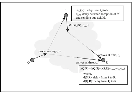
probe message, m
M{d(Q,S), dmM}
arrives at time, tm
arrives at time, tM d(Q,S): delay from Q to S dmM: delay between reception of m and sending out ack M.
d(Q,R) =d(Q,S)+d(S,R)+dmM-(tM-t m) where,
d(Q,R): delay from Q to R. d(S,R): delay from S to R. S
Q R
Figure 1: The delay estimation phase
sends the same message back to each of the receivers. By comparing the time this message is received with the time stored in the message, each receiver can compute the delay
d
(S;R
). As stated, this phase usesat most 2
n
messages each ofO
(1) size (assuming the granularity of time scale to be micro-seconds, thesize can be as large as four bytes). This phase can be simplified by letting the sender multicast a message containing the concatenation of all their message contents back to the receivers. This requires
n
messages of sizeO
(1), and one message ofO
(n
).Estimation phase In this phase, each receiver
R
determines the delay from every other receiverQ
toitself; here,
d
(S;R
)is used crucially.Figure 1 illustrates this part of the protocol. Fix a receiver
Q
. We focus on the problem of each receiverR
estimating the delay of transmissions fromQ
. ReceiverQ
multicasts a probe messagem
containingd
(A;S
)and the (local) time it sendsm
. Say the time this message is received by a receiverR
ist
m
. Thesender, upon receiving
m
, multicasts a messageM
comprisingd
mM
, the delay between receivingm
and sending outM
. SayM
is received byR
at timet
M
. The following holds.Lemma 3.1
d
(Q;R
)=d
(Q;S
)+d
(S;R
)+d
mM
?(t
M
?tm
).Proof. Let
t
be the time (in R’s clock) thatQ
sentm
. We can estimate the timet
in two different ways.Since
m
was received atR
at timet
m
,t
=t
m
?d
(Q;R
). Also sinceM
was received atR
at timet
M
,t
=t
M
?d
(S;R
)?d
mM
?d
(Q;S
). Both estimates oft
must be identical, hencet
m
?d
(Q;R
) =t
M
?d
(S;R
)?d
mM
?d
(Q;S
)from which the lemma follows.Thus every receiver
R
can computed
(Q;R
)for a fixedQ
. This takes2multicast messages each of sizeO
(1). Now, we repeat this process with each receiverR
playing the role ofQ
; at the end of this, everyreceiver
R
hasd
(R;Q
) for eachQ
. The whole process requires 2n
multicast messages each of sizeO
(1).We make two remarks.
Remark 1. One can optimize the number of messages to be
n
by allowing the sender to piggyback messagemessages (
m
’s) from all the receivers, and to multicast a cumulative acknowledgmentM
to all the receivers that containsd
mM
for allm
’s. This requiresn
probe messages each of sizeO
(1)and a single multicastmessage from the sender of size
O
(n
).Remark 2. The overall protocol is to run the setup and estimation phases alternately. By slightly modifying
the estimation protocol, we can ensure that following a single run of the setup phase, repeatedly running the estimation protocol itself suffices. The receiver
Q
now sends the messagem
comprising (a) the time the sender sent the last packet received byQ
from the sender (this information can be obtained from the packet) and (b) the delay between when the last packet from the sender was received byQ
and the current time whenQ
sends messagem
. The sender can determined
(Q;S
)from this information. Sender now broadcastsd
(Q;S
)andd
mM
as before, and the rest follows easily. The message complexity remains unchanged.The pseudo-code of this protocol appears below.
Receiver
i
’s protocol At every periodT
probe:probe sequence ++;
t
s
the time stamp in the last message from the sender;delay the delay from the reception of the last message from the sender multicast a probe
P
i
(probe sequence,t
s
,delay)On receiving a probe
P
i
(s,t
s
,delay): //received a probe message with sequence numbers
.Probe[
i
].time gettimeofday();Probe[
i
].seq s;if (Ack[
i
].seq = s) // if received the corresponding ack from the senderD
[i;j
]=(D
[i;S
]+D
[S;j
]?Ack[i
].delay) - (Probe[i
].time - Ack[i
].time);On receiving an ack ACK(i,s,delay,
d
i;S
)from the senderS
,Ack[
i
].time gettimeofday();Ack[
i
].seq s;Ack[
i
].delay delay;D
[i;S
]d
i;S
;if (Probe[
i
].seq = s) //if received the corresponding probe fromi
D
[i;j
] (D
[i;S
]+D
[S;j
]?Ack[i
].delay) - (Probe[i
].time - Ack[i
].time);Sender’s protocol
On receiving a probe
P
i
(s;t
s
;
delay):t
now
gettimeofday();D
[i;S
]t
now
?t
s
?delay;delay the delay from the reception of the probe message; multicast ACK(i,s,delay,
D
[i;S
]);4
Estimating network delay in a hierarchical scope
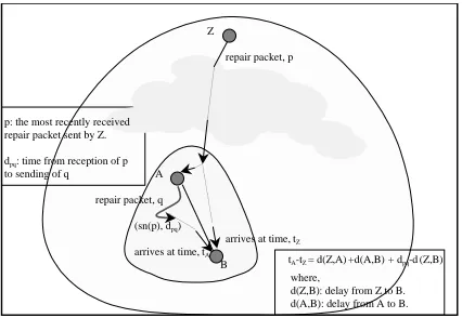
arrives at time, tZ repair packet, p
arrives at time, tA
tA-tZ = d(Z,A) +d(A,B) + dpq-d (Z,B) where,
d(A,B): delay from A to B. d(Z,B): delay from Z to B. (sn(p), dpq)
p: the most recently received repair packet sent by Z. dpq: time from reception of p to sending of q
repair packet, q Z
A
B
Figure 2: Hierarchical delay estimation
is multicasted to the entire scope. In presence of hierarchical scopes, the entire multicast group is broken into hierarchically nested scopes and designates a receiver within each scope as the zone closest receivers (ZCRs) [7] or designated receivers (DRs) [9]. In these protocols, typically receivers send feedback only to the ZCRs of their own scopes (i.e., their parents). Feedback transmitted directly to the sender or receivers outside their scopes is avoided to increase scalability.
Hierarchically scoped protocols, such as SHARQFEC [7], deal with this difficulty by assuming that ZCRs are at the multicast routes from the sender, and successively adding delays between a parent ZCR and its child ZCR. However, this assumption holds only when receivers has the knowledge of network topology.
In this section, we present a protocol that estimates the network delay from a ZCR
Z
(including the sender) to its receivers in its nesting scopes without any topological assumption or synchronized clocks. No feedback from the descendent receivers other than from the immediate children ofZ
is necessary. As before, we assume that network delays are symmetric.The protocol applies the principle discussed in Section 3 recursively in the hierarchical setting. Figure 2 illustrates the intuition behind the protocol. The objective is to estimate delays from
Z
to a receiverB
(d
(Z;B
)). Suppose that receiverA
is the ZCR ofB
, andA
is a descendent ofZ
. Note thatZ
can multicastrepairs (or data if the sender) to both
A
andB
. The delay betweenA
andB
(d
(A;B
)) can be computed asdescribed earlier (i.e.,
B
includes in the feedback the time stamp in the last message received fromA
).Suppose that receiver
B
knows the delay fromZ
toA
(d
(Z;A
)) (we will discuss how to estimate thisdelay lator). Then
d
(Z;B
)can be estimated byB
as follows. FirstZ
multicasts a repair packetp
to its basegroup to which both
A
andB
must belong. Lett
Z
be the time thatB
receives this packet according toB
’s clock. WhenA
receivesp
, it multicasts packetq
containing the sequence number of the last packet it received fromZ
and the delay from the reception of that packet to the sending ofq
which is denotedd
pq
. Lett
A
be the time thatB
receives packet iq
fromA
. We have the following:t
A
?T
Z
=d
(Z;A
)+d
(A;B
)+d
pq
?d
(Z;B
).It follows that,
d
(Z;B
)=d
(Z;A
)+d
(A;B
)+d
pq
?(t
A
?T
Z
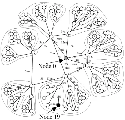
).10% 2% 1% 5% 10% 2% 1% 20ms 20ms 10% 1% 2% 3% 2% 3% 1% 1 1% 1% 1% 1% 5ms 3ms 7ms 14ms 7ms 9ms 12ms 10ms 11ms 13ms 8ms 9ms Node 19 Node 0
Figure 3: Network simulation topology with 113 nodes
scopes. This information can be piggy-backed on the repair packets it multicasts to
B
. This information would occupy no more thanO
(h
)space whereh
is the height of the tree of scopes. This does not add muchoverhead.
5
Simulation
5.1
Simulation setup
We implement our delay estimation protocol in UCB/LBNL/VINT, and study the performance of SRM with this new protocol. Our overall experimental setup is very similar to the one in [7].
Topology. Our simulation experiments were run using variants of the hybrid mesh tree topology used
in [7]. The two topologies used in our experiments are shown in Figure 3. their configuration is identical to the ones in [7] except for the loss rates assigned to each link. The sender at node 0 feeds data to a three level hierarchy of 112 receivers arranged as a mesh of 7 receivers each of which feeds balanced trees. Each of seven trees in the topology is an exact copy of each other, and three subtrees within each tree are also a copy of each other. The links connecting the source to the top 7 nodes in each tree are 45Mbits/s with all other links set to 10 Mbits/s. The latency between any two receivers located within each tree was set to 20 ms for each link while the latencies used for the backbone links are shown in the figures. The loss rates for the links are varied over different parts of the networks.
The loss model. To simulate a realistic loss behavior, we conducted transmission experiments over a
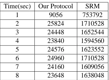
Time(sec) Our Protocol SRM
1 9056 753792
2 25824 1710528 3 24448 1652544 4 23840 1594560 5 24576 1623552 6 24960 1710528 7 24160 1609056 8 23648 1638048
Table 1: Bandwidth (bits/sec) used for delay estimation protocols measured at each second of simulation
received and lost. We gathered over100traces each15minutes long, and extracted the profile information
of each trace which comprises the loss characteristics of every non-overlapping 300 ms segment. The loss characteristics include the number of instances of loss bursts of lengths from 1 to over 200. For each link in the networks shown in Figure 3, we find a trace that undergoes the same average loss rate as that of the link, and use the trace to pick packets to drop during each 300 ms period. The loss rates for links are shown in Figure 3. The loss rates that receivers experience can be obtained by compounding the loss rates on the links from the sender to the receivers. In our topologies, they vary from1%to27
:
5%. Every packet passingthrough a link — data, repair, request, and session — is subject to the same loss rate indicated on that link.
Transmission. Each simulation experiment starts the session at time 1 second, at which time nodes begin
sending session messages, and after the initial bootstrap phase of 6 seconds, node 0 starts sending traffic at a constant bit rate of 800 Kbits/s. Each data packet is 1024 bytes. The sender stops transmitting data packets at time 16 seconds. Note that at this transmission rate, each receiver will get approximately 10 packets over a 100 ms period.
5.2
Simulation result
We implemented our delay estimation protocol and compared its overhead and performance with that of SRM’s session protocol. We use the topology shown in Figure 3 for simulation experiments. Table 1 compares the bandwidth overhead of our protocol with that of the SRM session protocol. Here the time interval between two consecutive transmissions of delay estimation probe (or session message) by the same receiver is set to one second. Our protocol uses only about 20 Kbits/s while the SRM session protocol uses over 1.6 Mbits/s. This is because the size of session messages in SRM is proportional to the number of receivers in the session, and each receiver sends at least one message per second. In contrast, our protocol uses only a constant size message.
6
7
8
9
10
11
12
13
14
15
Seconds
0.90
0.95
1.00
1.05
estimated RTT / actual RTT
Min
Max
Figure 4: Ratio of estimated RTTs over actual RTTs sampled over the running time period of SRM
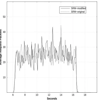
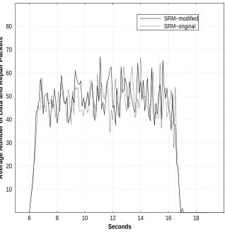
We also incorporated our protocol into SRM: we modified SRM to use our delay estimation to set its suppression timers. Figures 5 and 6 compare the average number of request and repair packets per receiver for the original SRM and that for the modified SRM. The graphs shows that using our scheme does not change the request and repair message traffic by a significant amount. This indicates that our delay estimation protocol can be used for suppressing request and repair as effectively as that in the original SRM that requires
O
(n
2
)message bit complexity.
6
Conclusion
6 8 10 12 14 16 18
Seconds
10 20 30 40 50
Average Request Packets
SRM−modified SRM−original
Figure 5: The impact of our protocol on the request suppression
unwanted traffic by using timers [5], use of FEC packets [12, 13, 7, 14, 15] etc. In this paper, we offer one additional tool, namely, a low-overhead protocol for estimating network delay between the receivers. We employ this tool on existing protocols and present simulation results that show the combined protocols to be substantially more scalable.
Our protocol runs on the assumption that delays between two processes are symmetric. This assumption may not hold in some situations such as sattelite or mobile wireless communications, and some wired lines. Our results on estimating oneway delay times in asymetric settings will appear in [16]
References
6 8 10 12 14 16 18
Seconds
10 20 30 40 50 60 70 80
Average Number of Data and Repair Packets
SRM−modified SRM−original
Figure 6: The impact of our protocol on the repair suppression
group meeting in Arlington, VA. Dec 1998.
[2] I. Rhee, N. Balaguru, and G. Rouskas. MTCP: Scalable TCP-like congestion control for reliable multicast. In Proceedings of the INFOCOM, New York, NY, March 99.
[3] B. Whetton and J. Conlan. A rate based congestion control scheme for reliable multicast. Technical report, GlobalCast Communication, Oct 1998.
[4] V. Jacobson. Congestion avoidance and control. ACM Communications Review, pages 314–329, August 1988.
[6] D. Mills. Network time protocol(v3). April 1992.
[7] R. G. Kermode. Scoped hybrid automatic repeat request with forward error correction (SHARQFEC). In Proceedings of the ACM SIGCOMM Conference, pages 278–289, October 1998.
[8] P. Sharma, D. Estrin, S. Floyd, and L. Zhang. Scalable session messages in SRM using self-configuration. Technical report, USC, July 1998.
[9] S. Paul, K. K. Sabnani, J. C. Lin, and S. Bhattacharyya. Reliable multicast transport protocol (RMTP). In Proceedings of the IEEE INFOCOM, San Francisco, CA, March 1996.
[10] R. Yavatkar, J. Griffioen, and M. Sudan. A reliable dissemination protocol for interactive collaborative applications. In Proceedings of ACM Multimedia, 1996.
[11] A. Basu and J. Golestani. Estimation of round trip times in multicast comnunication. Technical report, Bell Labs, Dec 1998.
[12] J. Nonnenmacher, E. Biersack, and D. Towsley. Parity-based loss recovery for reliable multicast trans-mission. In Proceedings of ACM SIGCOMM, September 1997.
[13] J. Gemmell. Scalable reliable multicast using erasure-correcting re-sends. Technical Report MSR-TR-97-20, Microsoft Research, June 1997.
[14] Dan Rubenstein, Jim Kurose, and Don Towsley. Real-time reliable multicast using proactive forward error correction. In NOSSDAV 98 (to appear).
[15] D. Rubenstein, S. Kasera, J. Kurose, and D. Towsley. Improving reliable multicast using active parity encoding services(apes). In To appear in IEEE Infocom ’99.