Research Development Cell, Government College of Engineering, Jalagon (M. S), India
Voltage Regulation and Reactive Power
Compensation by STATCOM based on
48-Pluse GTO (VSC)
Ajinkya Pachghare1, R.M.Sahare2
Department of Electrical Engineering, Government College of Engineering, Amravati, Maharashtra, India1
Department of Electrical Engineering, Government College of Engineering, Amravati, Maharashtra, India2
ABSTRACT: In this paper we presented STATCOM based on 48-pulse GTO for reactive power compensation and voltage regulation. Here we propose to tackle the existing problem in power transmission systems with multiple controller systems. The comprising a 48-pulse GTO(Gate Turn-Off) thyristor voltage source converter for combined reactive power compensation and voltage regulation of the electric grid network. This simulation of STATCOM are developed in MATLAB/simulink by utilizing the blocks from the power system block set mean while control system is modeled. The proposed work is to decouple the both voltage and current control strategy with two controllers by SATACOM. This problem is ensure that the system operates in stable condition with STATCOM with various loads and the phase locked loop inherent delay has a great effect on dynamic operation of STATCOM and also is to regulate the proposed technique and to enhance the dynamic performance of STATCOM this proposed 48 pulse control schemes are validated.
KEYWORDS: Gate Turn-Off (GTO), Static Shunt Compensator (STATCOM), voltage source convertor (VSC)
I.INRODUCTION
Research Development Cell, Government College of Engineering, Jalagon (M. S), India
II.STATCOM
The STATCOM is the static counterpart of the rotating synchronous condenser but it generates/absorbs reactive power at a faster rate because no moving parts are involved. In principle, it performs the same voltage regulation functions as the SVC but in robust manner because unlike the SVC, its operation is not impaired by the presence of low voltage. The STATCOM has superior performance during low voltage condition as the reactive current can be maintained constant. (In a SVC, the capacitive reactive current drops linearly with the voltage at the limit of capacitive susceptance). It is even possible to increase the reactive current in a STATCOM under transient conditions if the devices are rated for the transient overload. In 1976, Gyugyi discussed various switching power converters, which generating controllable reactive power directly without the use of ac capacitors or reactors. Functionality, from the standpoint of reactive power generation, their operation is similar to that of an ideal synchronous machine whose reactive power output is varied by excitation control. Like the mechanically powered machine these converters can also exchange real power with the ac system if supplied from a suitable, generally dc energy source. Because of these similarities with a rotating synchronous generator, they are termed Static Synchronous Generator (SSG). When SSG isoperated without an energy source and with appropriate controls to function as shunt-connected reactive compensator, it is termed, analogously to the rotating synchronous compensator (condenser) a Static Synchronous Compensator (STATCOM) or Static Synchronous Condenser (STATCON).
Fig-1: Static Synchronous Compensator (STATCOM) based on (a) Voltage sourced (b) current sourced converter
III. SYSTEM DEVLOPMENT
Research Development Cell, Government College of Engineering, Jalagon (M. S), India
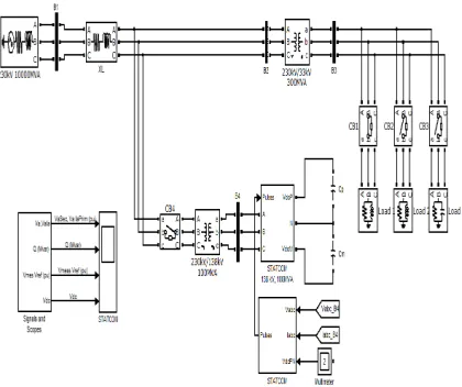
standards. Simulation model of 48-pulse VSC based STATCOM FACTS devices. This full model is validated for voltage stabilization reactive power compensation and dynamic power flow control. It produces a sinusoidal AC voltage with minimal harmonic distortion from a DC voltage with variable loads. Also investigated that the GTO based STATCOM consisting a 48-pulse three-level inverter regarding minimal harmonic distortion. It has fine dynamic response and can regulate transmission system voltage efficaciously.
Fig-2: 48-pluse GTO (VSC)
IV. DECOUPLED CURRENT CONTROL SYSTEM
Research Development Cell, Government College of Engineering, Jalagon (M. S), India
Fig 3: Control scheme for STATCOM
V.SIMULATION RESULTS
The model of STATCOM Control System is shown figure. Its task is to increase or decrease the capacitor DC voltage, so that the generated AC voltage has the correct amplitude for the required reactive power. The control system must also keep the AC generated voltage in phase with the system voltage at the STATCOM connection bus to generate transformer and inverter losses. Voltage regulation it is performed by two PI regulators: from the measured voltage Vrms and the reference voltage Vref, the Voltage Regulator block (outer loop computes the reactive current reference Iqref used by the current regulator block (inner loop). The output of the current regulator is α angle which is the phase shift of the inverter voltage with respect to the system voltage.
Research Development Cell, Government College of Engineering, Jalagon (M. S), India
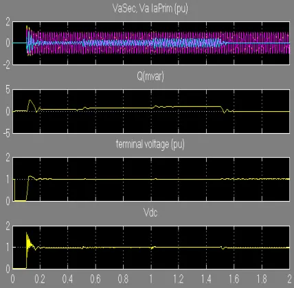
Fig 5: Result of STACOM
VI. CONCLUSION
Research Development Cell, Government College of Engineering, Jalagon (M. S), India
REFERENCES
[1] M. S. El-Moursi and A. M. Sharaf,“Novel Controllers for the 48-Pulse VSC STATCOM and SSSC for Voltage Regulation and Reactive Power
Compensation” IEEE TRANSACTIONS ON POWER SYSTEMS, VOL. 20, NO. 4, NOVEMBER 2005
[2] C. Schauder and H. Mehta ―Vector analysis and control of advanced static var compensatorǁ inProc. Inst. Elect. Eng. Int. Conf. AC DC Transmission 1991 pp. 299–306. Paper no. 345.
[3] D.Soto and C. Green ―A comparison of high-power converter topologies for the implementation of facts controllersǁ IEEE Trans. Indust. Electron. vol. 49 no. 5 pp. 1072–1080 Oct. 2002.
[4] K. K. Sen ―SSSC—static synchronous series compensator: Theory modeling and applicationǁ IEEE Trans. Power Del. vol. 13 no. 1 pp. 481–486 Jan. 1998.
[5] R. M. Mathur and R. K. VarmaThyristor-Based FACTS Controllers for Electrical Transmission Systems. Piscataway NJ: IEEE Press 2002. [6] Sahoo A. K. Murugesan K. Thygarajan T. ―Modelling and Simulation of 48-pulse VSC based STATCOM using Simulink’s Power System
Blocksetǁ Proceedings of India International Conference on Power Electronics pp. 303-308 December 2006.
[7] Huang S. P. Li Y. J. Jin G.B. Li L. ―Modelling and Dynamic Response Simulation of GTO based STATCOMǁ Proceedings of the International Conference on Electrical and Control Engineering pp. 1293-1296June2010
[8] X.-P. Zhang, ―Advanced modeling of the multicontrol functional static synchronous series compensator (SSSC) in Newton power flow,ǁ IEEE
Trans. Power Syst., vol. 18, no. 4, pp. 1410–1416, Nov. 2003.