Compact, Self-Isolated 2.4/5-GHz WLAN Antenna for Notebook
Computer Applications
Che-Chi Wan and Saou-Wen Su*
Abstract—A simple and compact, self-isolated printed antenna able to operate in the 2.4 GHz (2400– 2484 MHz) and 5 GHz (5150–5825 MHz) wireless local area network (WLAN) bands in notebook computers is introduced. The design is built on a low-cost substrate with the dimensions 6 mm×30 mm (about 0.05λ×0.24λat 2.4 GHz) and comprises a symmetrical coupled-fed loop and two parasitic shorted strips. For size reduction, the 2.4 GHz loop is loaded with a pair of L-shaped stubs above the feeding and coupling T strip. The parasitic strips shorted on both sides of the coupling T strip are further added to generate the 5 GHz band resonance. The results show that good radiation characteristics can be obtained in the bands of interest. In addition, when grouping three proposed designs with a gap of 4 mm between them, the results for each antenna impedance bandwidth, the isolation between any two of the three designs, and the envelope correlation coefficient (ECC) are also satisfactory.
1. INTRODUCTION
Quite recently, the internal antennas with the self-decoupled [1, 2] or self-isolated [3, 4] properties in the multiple antenna system have been reported for 4G and 5G mobile phone applications. These antennas when combined in close proximity offer attractive features in which no additional decoupling structures are required for acceptable port decoupling and low envelope correlation coefficients (ECCs). The isolation level of the worst case (largest value) for the antennas studied in [1, 2] reaches 10 dB while that in [3, 4] is much better and at about 18 dB. Moreover, the self-isolated antenna design shown in [4] is actually derived from a similar design in [3] for overall size reduction. Nonetheless, these two antennas [3, 4] can only operate in the single band at 3.5 GHz (3400–3600 MHz).
In this paper, a new, compact, and printed self-isolated antenna targeted at dual-band operation in the 2.4 GHz (2400–2484 MHz) and 5 GHz (5150–5825 MHz) wireless local area network (WLAN) bands for notebook computers is introduced. The antenna is fabricated on a low-cost substrate of size 6 mm×30 mm (about 0.05λ×0.24λat 2.4 GHz), including the small antenna ground of size 1 mm×30 mm and placed above the top edge of the supporting metal plate of a notebook display. The design has a symmetrical structure and comprises a coupled-fed loop with a feeding, coupling T strip, and two parasitic shorted strips. The loop and the antenna ground form a close-form loop structure for 2.4 GHz operation while the parasitic strips on both sides of the coupling T strip are added to generate the 5 GHz band resonance. Thereby, a dual-band WLAN operation can be achieved for the proposed self-isolated antenna. The design prototype and results thereof are described and discussed in the article.
Received 21 April 2019, Accepted 26 June 2019, Scheduled 11 July 2019 * Corresponding author: Saou-Wen Su (Saou-Wen [email protected]).
(a) (b)
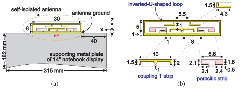
Figure 1. (a) Geometry of the self-isolated, dual-WLAN-band antenna placed above the top edge of the supporting metal plate of a 14-inch notebook display. (b) Detailed parameters of the design prototype.
Details of the proposed, self-isolated antenna are shown in Fig. 1(b). The design has a symmetrical structure and comprises a coupled-fed, inverted-U-shaped loop and two parasitic shorted strips. In the middle of the loop are further loaded a pair of the L-shaped stubs above the feeding, coupling T strip for overall size reduction [4]. The widths of the inverted-U-shaped loop, the loaded stubs, and the coupling strip are all set to 0.5 mm for ease of studies. In this design, the loop and the antenna ground form a close-form loop structure, operating at the one-wavelength loop resonant mode in the 2.4 GHz band. Moreover, in order to achieve the additional upper band to cover the 5 GHz band for dual-WLAN-band notebook antennas, the parasitic shorted strips are symmetrically added on both sides of the feeding, coupling T strip.
To keep a low profile of 6 mm (about 0.05λ at 2.4 GHz) and at the same time, to accommodate the 5 GHz parasitic strips, the loaded stubs above the coupling strip are designed to be bent into an L shape, different from those vertical stubs reported in the single-band, 3.5 GHz self-isolated antenna [4], in which the antenna height of about 0.07λ at 3.4 GHz is larger. In this design, the length L of the loaded stubs and the gap gbetween the coupling strip and the parasitic strips (see insets in Fig. 7) are used and carefully fine-tuned for adjusting the 2.4 and 5 GHz bands respectively. The results of the related studies and the controlling mechanism will be discussed in the following sections.
3. EXPERIMENTAL AND SIMULATION RESULTS
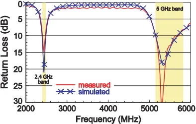
Figure 2. Measured and simulated return losses for the proposed antenna.
in the 2.4 and 5 GHz bands all exceeds the 7.3-dB return loss (about VSWR of 2.5), which is widely accepted for the industrial specification for small-sized, WLAN notebook antenna applications.
The corresponding, simulated surface-current distributions in vector forms for the design excited at 2445 and 5490 MHz are presented in Fig. 3. First, the surface currents for 2.4 GHz operation are seen mostly populated on the coupling T strip and the close-form loop structure, including the current path on the small antenna ground. Two current nulls, denoted as a cross in the figure, are seen in the middle of the inverted-U-shaped loop above the coupling strip and on the antenna ground below the feed port. This behavior suggests that the inverted-U-shaped loop in combination with its image currents on the antenna ground exhibit a self-balanced, one-wavelength loop resonance [6–11]. Thus, the 2.4 GHz loop in this design can offer the self-isolated properties [3, 4] when more than two of the said loops are employed in the multiple antenna system. For the antenna excited at 5490 MHz, relatively larger currents are distributed on the driven coupling strip and the two parasitic strips (no current nulls observed on parasitic strips). These results indicate that the 5 GHz operation is mainly attributed to the quarter-wavelength monopole mode of the two parasitic strips.
f = 5490 MHz f = 2445 MHz
null
f = 5490 MHz f = 2445 MHz
null
Figure 3. Simulated surface currents in the form of vectors at 2445 and 5490 MHz for the antenna in Fig. 2.
Figure 4. Simulated return losses for the proposed antenna, Ant1 (proposed without two parasitic strips), and Ant2 (proposed without L-shaped stubs); other dimensions remain the same as studied in Fig. 2.
only (without U-shaped loop, loaded stubs, and shorted strips) are also investigated but not shown for brevity. Over the 2–6 GHz frequency range, the resistance of the input impedance is at a level of about 7–11 Ω with zero reactance about 6 GHz, suggesting that the coupling strip is non-responsive and does not interfere with the desired operating bands.
The antenna over-the-air (OTA) performance was studied, and the measurement was taken at our SATIMO chamber of model SG 64 [12]. Fig. 5(a) and (b) shows the measured radiation patterns in Eθ and Eφ fields for the antenna at 2442 and 5490 MHz, the center frequencies of the 2.4 and 5 GHz WLAN bands. The two-dimensional (2D) patterns are normalized with respect to the peak antenna gain in each cut. In general, the omnidirectional radiation patterns are observed in the x-y planes over the lower and the upper bands. In the elevation planes (x-z and y-z cuts), the radiation patterns at 2442 MHz are different from those of the quarter-wavelength monopole and IFA designs [13, 14], in which larger radiation above the display ground plane is observed. Instead, in this study the pattern nulls occur in the +zdirection in the lower band; this characteristic is similar to the radiation patterns of the one-wavelength loop structure at 5775 MHz in [15]. For radiation at 5490 MHz, the patterns contributed to by the two parasitic strips yield similar radiation to the radiation at the said frequency of the quarter-wavelength monopole that has the 2.4 GHz resonant portion loaded to the 5 GHz one [14]. Fig. 6 presents the measured peak antenna gain and antenna efficiency against frequency. The peak gain in the 2.4 GHz band is about 4.4 dBi with antenna efficiency of 63–71%. For 5 GHz band, the gain is in the range of 4.2 to 5.4 dBi with efficiency of 63–75%. Notice that the OTA measurement here took account of antenna mismatch loss; the realized gain [16] and the antenna efficiency [17] are thus measured in the chamber.
4. PARAMETRIC STUDIES
(a)
(b)
Figure 5. Measured 2D radiation patterns of the proposed antenna at (a) 2442 MHz and (b) 5490 MHz.
Figure 6. Measured peak antenna gain and antenna efficiency for the antenna studied in Fig. 5.
(a) (b)
Figure 7. Simulated return losses as a function of (a) the lengthL of the L-shaped stubs and (b) the gap g between the coupling T strip and the parasitic strips.
upper band increase. Notice that a larger value of the gap g will lead to strong coupling between the open end of the strip and the inverted-U-shaped loop, which can degrade the desired 5 GHz band. The results shown in Fig. 7 also reflect that the occurrence of the upper-band resonance is dominated by the parasitic strips as discussed in Fig. 4.
5. THREE-SELF-ISOLATED-ANTENNA SYSTEM
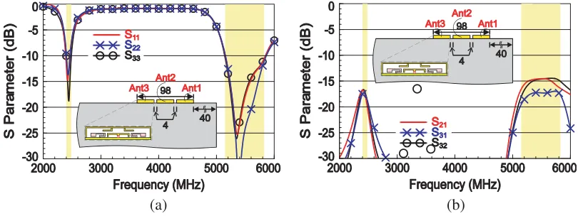
Three proposed antennas arranged in close proximity and placed above the display metal plate (see inset in Fig. 8) are also studied. The dimensions for all these antennas remain the same (no re-optimization). The distance between the two nearby antennas (Ant1&2 and Ant2&3) is set to 4 mm (less than 0.03λ at 2.4 GHz) such that the total length of the three-antenna system is no more than 100 mm, which is conventionally required by the antenna suppliers for the two-WLAN-antenna system in the notebook industry. The simulated S-parameters of the three antennas are presented in Figs. 8(a) and (b). The resonance and the impedance matching for 2.4 GHz operation are almost the same, and the isolation is better than 17 dB. For 5 GHz operation, the obtained impedance bandwidth is about the same with port-to-port isolation better than 14 dB. Notice that the isolation is even better than 17 dB between Ant1 and Ant3 because these two antennas are spaced farthest apart (38 mm in this case).
Due to the symmetrical structure together with the self-isolated properties, the proposed design can be combined with the same on both sides with similar isolation characteristics. From the results
(a) (b)
Figure 8. Simulated S-parameters for the three self-isolated antennas placed above the display metal plate: (a) S11 for Ant1, S22 for Ant2, S33 for Ant3 and (b) S21, S31, S32 for isolation between these
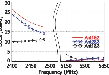
Figure 9. Simulated ECCs based on the simulated, complex, E-field radiation patterns for Ant1, Ant2, Ant3 studied Fig. 8.
in Fig. 8, it is clearly seen that the isolation in the 2.4 GHz band for Ant1&2, Ant2&3, Ant1&3 is very similar. However, if the separation distance between the antennas further reduces to 2 mm (results not shown for brevity), the isolation in the 2.4 and 5 GHz bands can become poor at about 12 dB, which is unwanted. The ECCs for the three-antenna system are shown in Fig. 9. The envelope correlation is also obtained from the ANSYS HFSS simulation, which computes the Hermitian product of the two far-field radiation patterns with each normalization [18]. Good ECCs of less than 0.26 and 0.04 are obtained over the 2.4 and 5 GHz bands respectively, which are better than the value 0.5 as suggested for mobile devices reported in [19].
6. CONCLUSION
A low-profile, self-isolated printed antenna well suited to notebook applications for dual-band WLAN operation has been presented. The compact footprint of the design, including the small antenna ground, occupies merely a small size of 6 mm×30 mm. The self-isolated properties in the 2.4 GHz band are formed by using the close-form loop structure operating at its one-wavelength resonance and fed by a coupling T strip. The compactness of the design is achieved by loading a pair of the L-shaped stubs in the middle of the loop above the coupling strip. By carefully adding two parasitic strips to the loop, additional monopole resonance for 5 GHz operation can be attained. The measured antenna efficiency for both the 2.4/5 GHz bands exceeds 63%. For the three-proposed-antenna system, the simulated port isolation between any two antennas is better than 17 and 14 dB with the ECCs less than 0.26 and 0.04 over the 2.4 and 5 GHz bands. The proposed self-isolated antenna can be a good candidate for future multiple notebook antennas in the Gbps communications.
REFERENCES
1. Wong, K. L., C. Y. Tsai, and J. Y. Lu, “Two asymmetrically mirrored gap-coupled loop antennas as a compact building block for eight-antenna MIMO array in future smartphone,” IEEE Trans. Antennas Propagat., Vol. 65, 1765–1778, 2017.
2. Wong, K. L., C. C. Wan, and L. Y. Chen, “Self-decoupled compact metal-frame LTE MIMO antennas for the smartphone,” Microwave Opt. Technol. Lett., Vol. 60, 1170–1179, 2018.
3. Zhao, A. and Z. Ren, “Multiple-input and multiple-output antenna system with self-isolated antenna element for fifth-generation mobile terminals,” Microwave Opt. Technol. Lett., Vol. 61, 20–27, 2019.
4. Zhao, A. and Z. Ren, “Size reduction of self-isolation MIMO antenna system for 5G mobile phone applications,” IEEE Antennas Wireless Propagat., Vol. 18, 152–156, 2019.
5. ANSYS HFSS, ANSYS Inc., https://www.ansys.com/Products/Electronics/ANSYS-HFSS. 6. Su, S. W., “High-gain dual-loop antennas for MIMO access points in the 2.4/5.2/5.8 GHz bands,”
12. SG 64, SATIMO, http://www.mvg-world.com/en/products/field product family/antenna-measurement-2/sg-64.
13. Su, S. W., “Very-low-profile, 2.4/5-GHz WLAN monopole antenna for large screen-to-body-ratio notebook computers,”Microwave Opt. Technol. Lett., Vol. 60, 1313–1318, 2018.
14. Su, S. W., “Very-low-profile, small-sized, printed monopole antenna for WLAN notebook computer applications,” Progress In Electromagnetics Research Letters, Vol. 82, 51–57, 2019.
15. Su, S. W., “Capacitor-inductor-loaded, small-sized loop antenna for WLAN notebook computers,” Progress In Electromagnetics Research M, Vol. 71, 179–188, 2018.
16. Volakis, J. L., Antenna Engineering Handbook, 4th Edition, Chapter 6, 16–19, McGraw-Hill, New York, 2007.
17. Balanis, C. A., Antenna Theory: Analysis and Design, 3rd Edition, Chapter 2, Wiley, Hoboken, NJ, 2012.
18. Blanch, S., J. Romeu, and I. Corbella, “Exact representation of antenna system diversity performance from input parameter description,” Electronics Lett., Vol. 39, 705–707, 2003.