Concept of Experimental Simulator for Studying Longitudinal
Magnetic Wave Propagation in Dielectric Samples
Yuriy M. Penkin, Viktor A. Katrich, Dmitriy Yu. Penkin, and Mikhail V. Nesterenko*
Abstract—A concept of an experimental simulator for studying longitudinal magnetic waves in dielectric samples and its electrodynamic justification are presented. The simulator is intended to control impact power and frequencies of wave processes. The simulator is realized as a two-channel junction consisting of perpendicularly crossed infinite rectangular waveguides with slot coupling. The simulation process is based on cyclic mechanical displacements of dielectric samples along the longitudinal axis of the waveguide in a quasi-stationary magnetic field localized in the slot region.
1. INTRODUCTION
In recent years, an intensive growth of research interest has been observed in study of longitudinal electromagnetic waves with components of the electric E or H magnetic fields oriented in the wave propagation direction k [1]. Longitudinal electromagnetic waves are classified depending on mutual orientation of vectors E,H andk into four classes: electric waves (E is parallel tok), magnetic waves (H is parallel tok), torsional waves (H is parallel tok, and a vortex E component is present), and Tesla waves (E is parallel tok, and a vortexH component is present). As known, Maxwell’s equations in the form proposed by Heaviside and Hertz [2] do not allow propagation of longitudinal waves in free space at large distances. Nevertheless, in complex and moving media, this possibility may exist within the framework of classical electrodynamics, e.g., [3]. However, in some composite media, surface waves can be observed in a near zone of radiators as longitudinal field components interpreted as damped longitudinal waves of a hybrid type [4]. Despite existing theoretical discrepancies, some devices, such as surface wave generators, transverse-to-longitudinal wave transducers, detectors, mixers, and power meters in different frequency ranges, have been developed [5]. Plasma devices, with radial currents, gas-discharge tubes, quarter-wave resonators, etc., can be used as generator elements. Longitudinal waves are usually registered by Schottky diodes, photographic materials protected by opaque screens, liquid crystal indicators, etc. In other words, these devices can be characterized by specific and rather complicated methods of their construction.
In addition to communication applications, longitudinal wave effects on dielectric and biochemical objects are important due to their specific properties and high penetrability. For example, studies of mutagenic and stimulating effects of longitudinal electromagnetic radiation on biological objects are important for medical applications [6]. Such studies require accurately monitoring the radiation power and fine frequency tuning of the wave process at sufficiently low frequencies commensurate with the natural frequencies of biologic objects. However, at present there are no experimental tools offering such a possibility. This article is aimed at the development of a concept and electrodynamic justification of a relatively simple experimental simulator intended for modelling propagation of longitudinal magnetic
Received 27 September 2018, Accepted 23 October 2018, Scheduled 29 October 2018
* Corresponding author: Mikhail V. Nesterenko ([email protected]).
waves in dielectric samples. The simulator can control impact power and frequencies of wave processes in dielectric samples.
2. ELECTRODYAMIC ANALYSIS OF THE BASIC WAVEGUIDE DEVICE
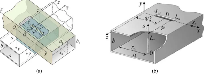
Let us consider a junction of two crossed infinite rectangular waveguides with perfectly conducting walls coupling trough a narrow transverse slot (Fig. 1(a)). The longitudinal axes of the waveguide are crossed at right angle. The lower waveguide radiates into the upper one through the slot cut in the wide walls of the waveguides along transverse axis of lower waveguide. Internal cross sections of the lower and upper waveguides, a×b and a1×b1, guarantee the single-mode operation of the waveguides. The length,
width, and thickness of the slot (2l, d and h) are such that inequalities [d/(2l)] 1, [d/λ] 1, and
hλ(λis wavelength in free space) hold. The upper waveguide is hollow, while a dielectric insert of finite lengthcwith an arbitrary permittivityεand permeabilityμ= 1 are located under the slot in the lower waveguide. The lower waveguide is excited by a unit amplitude wave H10 propagating from the
directionz=−∞.
(b) (a)
Figure 1. Geometry of the waveguide devices.
Since the coordinate along longitudinal axis of the upper waveguide is ¯x0 = a1/2, the waveguide
mode becomes evanescent, i.e., the slot does not excite propagating waves, and the microwave power concentrates in the region limited by the slot. Earlier, a similar junction mode was considered based on mathematical modeling [7]. It was shown that atx0 =a/2, the maximum power transfer from the lower
to the upper waveguide can be achieved when the distancez0(measured along axiszas shown in Fig. 1)
between the longitudinal slot axis and left boundary of the insert is close to d/2. If the insert length is large, the maximum power transfer is obtained under condition that z0 is a multiple of λεg/2 (λεg is wavelength in the lower waveguide completely filled with a dielectric). In this case, the longitudinal dimension of the insert, c, should be multiple of an odd number of λεg/4. It was also shown that the power transmission level from the lower to upper waveguide in the range of 0 ≤ |Se|2 ≤ 0.84 can be achieved by varying the insert permittivity.
The|Se|2 value can also be controlled by an asymmetrical thin impedance vibrator located parallel to the narrow walls in the lower waveguide [8]. The structure is shown in Fig. 1(b). If the vibrator radius r and length 2Lv satisfy the inequality [r/(2Lv)] 1 and x01 = a/2, the maximal radiation
coefficient of the slot can be achieved if the vibrator inductive impedance varies along its axis. In this case, the intrinsic resonant wavelengths of the slot and vibrator should differ at about 20%. The mutual influence between the elements of the vibrator-slot structure is manifested if the vibrator is placed along the longitudinal axis of the waveguide at the distancez0, which is multiples of λG/4 (λGis the resonant
wavelength of the slot in the waveguide). The maximal radiation coefficient of the slot is achieved if displacement z0 is multiples of λG/2.
an equivalent longitudinal magnetic current [9]
jzm¯ (¯x,y,¯ z¯) =z¯0J0m Φ (¯x,y¯) cosq(¯z−l)|y¯=b1, (1)
whereJ0m is the complex amplitude; Φ (¯x,y¯) is a predefined function; the parameterq=π/(2l). Using
the well-known relations for the Hertz vector and the magnetic tensor Green’s function [9], we can obtain expressions for electric E¯ and magnetic H¯ fields in the waveguide, which can be characterized by an interesting feature: the transverse components of theE¯ and H¯ fields corresponding to the mode
m = n = 0 (m, n are indices of the Green’s function presented in the form of a double sum) are everywhere equal to zero. Therefore, only the longitudinal component ¯Hz¯00 is nonzero in the slot
region, where it turns out to be purely reactive. Hence,
¯
Hz¯00= ⎧ ⎪ ⎨ ⎪ ⎩
iJ0m a1b1ωμ
¯
x
Φx¯, b1
dx¯cosq(¯z−l), 0≤z¯≤2l;
0, z¯≤0, 2l≤z¯;
(2)
whereωμ= 120πk andk= 2π/λis the wave number in the upper waveguide.
The analysis of expression (2) show that the magnetic field ¯Hz¯00 has a quasi-static character and
can be presented in the slot region 0≤z¯≤2l by standing wave, expressed by a half-wave cosine curve. The importance of this component for modeling the radiation field by longitudinal slots was justified for the first time in [10].
Thus, we can state that a localized quasi-stationary magnetic field represented by a standing wave in the region of the coupling slot is excited in the upper waveguide of the cruciform waveguide junction. The field magnitude can be controlled by the element located in the lower waveguide. The required slot length depends on the operating wavelength and the electrical parameters of the waveguide junctions in the centimeter or decimeter wavelength range.
3. SIMULATION OF LONGITUDINAL MAGNETIC WAVE PROPAGATION
Analysis of the basic waveguide junction is presented for the hollow upper waveguide. It is self-evident that the results remain physically correct when the upper waveguide is filled with a homogeneous non-magnetic dielectric with permeabilityε, since the amplitude of the quasi-stationary field ¯Hz¯00in Eq. (2)
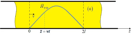
does not depend on the material parameter. Then we can assume that the cross-sections of the dielectric bar and upper waveguide coincide, and the bar can move along the waveguide longitudinal axis with small velocity v as compared with light velocity and relaxation rates of dielectric atoms and molecules (Fig. 2).
Figure 2. Dielectric sample in a magnetic field in the upper waveguide.
Then, a flat layer of the dielectric bar located under the slot at the position ¯z= 0 at the timet= 0 (Fig. 2) interacts with the magnetic field characterized by a time-varying amplitude
¯
H¯z00(t) = iJ
m
0 a1b1ωμ
¯
x
Φx¯, b1
dx¯cosq(vt−l) (3)
sample interacts with the magnetic field
¯
Hz¯00(t) = iJ
m
0 a1b1ωμ
¯
x
Φx¯, b1
dx¯cosq 2l
Δtt−l
, (4)
at the time interval 0 ≤ t ≤ 4l/v until the bar returns to its initial position. Thus, the periodic displacement of the dielectric bar produces electrodynamic conditions corresponding to the effect created by a longitudinal magnetic wave with a frequencyν = πΔlt. Thus, the frequency and time parameter Δtof the simulated wave process can be controlled by varying the velocity of the dielectric sample.
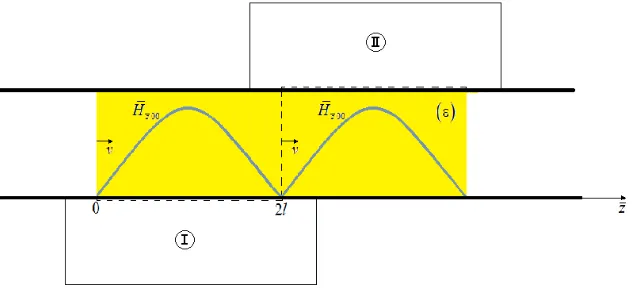
To ensure simulation of the wave process in any cross section of the dielectric sample, occupying the waveguide region above the slot, the basic design of the waveguide device should be modified as follows. Let two identical waveguides be coupled with common waveguide arm with the moving dielectric bar through two identical slots cut in the lower and upper waveguides, I and II, as shown in Fig. 3. The lower and upper slots are aligned in the plane ¯z = 2l to ensure the continuity of the distribution of the quasi-stationary magnetic field ¯Hz¯00, which in the waveguide region 0≤z¯≤4l consists of the two
standing half-waves.
Figure 3. Sketch of the proposed waveguide device geometry.
It is easy to verify that such a magnetic field structure can be applied to simulation of wave processes at an arbitrary point in any cross-section of the dielectric sample. It should be noted that the coupling slots of the proposed waveguide device with two independent inputs do not interact with each other over higher waveguide modes. Thus, the waveguide inputs do not require any additional tuning when they are used together.
4. CONCLUSION
The concept of the simulator intended for studying propagation of longitudinal magnetic waves in homogeneous dielectric samples is developed. Simulation of the wave process is carried out by mechanical displacement of the dielectric sample in the quasi-stationary magnetic field concentrated in the finite segment of the rectangular waveguide. The magnetic field with required structure is formed by two coupling slots cut in the waveguide arms of the two-channel junction consisting of perpendicularly crossed rectangular waveguides. The proposed waveguide device with the two identical excitation ports can form a quasi-stationary magnetic field based on the electrodynamic approach at any operating wavelength in centimeter or decimeter wavelengths.
REFERENCES
1. Ageyev, I. M. and G. G. Shishkin, Longitudinal Waves, Moskow, MAI, 2014 (in Russian). 2. Hertz, H., Untersuchungen Uber die Ausbreitung der Elektrischen Kraft, Leipzig, 1894.
3. Ginzburg, V. L.,Propagation of Electromagnetic Waves in Plasmas, Pergamon Press, Oxford, New York, 1970.
4. Monstein, C. and J. P. Wesley, “Observation of scalar longitudinal electrodynamic waves,”
Europhys. Lett., Vol. 59, No. 4, 514–520, 2002.
5. Abdulkerimov, S. A., Yu. M. Yermolayev, and B. N. Rodionov, Longitudinal Eelectromagnetic Waves. Theory, Experiments, Prospects of Application, Moskow, MGUL, 2003 (in Russian). 6. Bogdanov, V. P., Ye. I. Nefedov, and A. A. Protopopov, “Analysis of the mutagenic and stimulating
effect of longitudinal electromagnetic radiations,” Elektrodinamika and Tekhnika, Vol. 8, No. 1– 2(27), 37–41, 2000 (in Russian).
7. Penkin, Yu. M., S. L. Berdnik, V. A. Katrich, and M. V. Nesterenko, “Influence of a dielectric insert on energy characteristics of a cruciform waveguide junction,” Proc. XXI-th Inter.Seminar/Workshop “Direct and Inverse Problems of Electromagnetic and Acoustic Wave Theory”, 42–45, Tbilisi, Georgia, 2016.
8. Nesterenko, M. V., V. A. Katrich, D. Yu. Penkin, S. L. Berdnik, and V. I. Kijko, “Electromagnetic waves scattering and radiation by vibrator-slot structure in a rectangular waveguide,” Progress In Electromagnetics Research M, Vol. 24, 69–84, 2012.
9. Nesterenko. M. V., V. A. Katrich, Yu. M. Penkin, and S. L. Berdnik,Analytical and Hybrid Methods in Theory of Slot-Hole Coupling of Electrodynamic Volumes, Springer Science + Business Media, New York, 2008.