RADIATION PROPERTIES ENHANCEMENT OF TRIANGULAR PATCH MICROSTRIP ANTENNA ARRAY USING HEXAGONAL DEFECTED GROUND STRUCTURE
F. Y. Zulkifli, E. T. Rahardjo, and D. Hartanto
Electrical Engineering Department University of Indonesia
Depok, West Java, Indonesia
Abstract—This paper presents a hexagonal shape defected ground structure (DGS) implemented on two element triangular patch microstrip antenna array. The radiation performance of the antenna is characterized by varying the geometry and dimension of the DGS and also by locating the DGS at specific position which were simulated. Simulation and measurement results have verified that the antenna with DGS had improved the antenna without DGS. Measurement results of the hexagonal DGS have axial ratio bandwidth enhancement of 10 MHz, return loss improvement of 35%, mutual coupling reduction of 3 dB and gain enhancement of 1 dB.
1. INTRODUCTION
Recently introduction of EBG and DGS made a significant break-through in the improvement of microstrip antennas characteristics. EBG are a new type of engineered materials with periodic structures that can control the propagation of electromagnetic waves to an extent that was previously not possible. However, in implementing EBG, a large area is needed to implement the periodic patterns and it is also difficult to define the unit element of EBG. Whereas DGS has similar microwave circuit properties as EBG, it can also modify guided wave properties to provide a bandpass or bandstop like filter and can easily define the unit element. DGS is realized by etching the ground plane of microstrip antenna, this disturbs the shield current distribution in the ground plane which influences the input impedance and current flow of the antenna. The geometry of DGS can be one or few etched structure which is simpler and does not need a large area to implement it.
Many shapes of DGS slot have been studied for single element microstrip antenna such as circle [2], dumbbells [3] and spiral [4], however not many have realized it in antenna arrays. In [5], they proposed using a dumbbell EBG structure and in [6] using a fork-like EBG structure. Both references implemented EBG between two element arrays, these antenna designs are complex structure. The author found papers by Salehi et al. [7] and by Zainud-Deen et al. [8] which used dumbbell shape DGS for antenna array, however the results were simulation one and not realized through experimental results.
In an antenna array, the mutual coupling effect will deteriorate the radiation properties of the array. Therefore in this study, the reduction of the mutual coupling effect was investigated by proposing a new hexagonal shape DGS to be implemented between the two elements triangular patch microstrip antenna array. Simulation and measurement results have been done and showed that the antenna with DGS can improve the antenna performance of the antenna without DGS.
This paper discusses the influence of hexagonal shape DGS towards the improvement of the radiation properties. By adding the DGS, therefore, will suppress surface wave propagation in the dielectric layer.
2. ANTENNA DESIGN
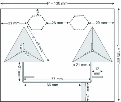
A configuration of double hexagonal DGS implemented to the antenna is shown in Fig. 1. The antenna without DGS, as in [9], is designed on a single layer dielectric substrate with εr = 2.2, thickness of 1.57 mm
polarized bandwidth of minimum 50 MHz and resonant frequency at 2.61 GHz. Two element triangular microstrip antenna arrays with a distance between each element of 77 mm are fed asymmetrically to achieve tilted angle radiation pattern towards 30◦. The stub is given for matching in the antenna without DGS and the Y slot in the triangular patch is inserted to excite circular polarization.
The DGS is then inserted into the ground plane of the antenna with position between the two element triangular patch. In Fig. 1, the DGS is drawn with dash lines to indicate that the DGS is located on the bottom of the substrate. The patch and the feeding system with stub from the antenna are not changed; only hexagonal shape slot is inserted to the ground plane of the antenna.
Figure 1. Configuration of double hexagonal DGS antenna design. The proposed hexagonal DGS design in this paper was simulated by varying the dimension and locating the position of the DGS on the antenna without DGS. The first simulation used one hexagonal DGS implemented to the antenna and showed no significant result. However, the best result shown for a single hexagonal is when the area of the hexagonal equals to 259 mm2 with the side length of 14 mm. Therefore, based on the previous simulation, the next one is expanded to two hexagonal DGS with the total area of the DGS maintained at 259 mm2. The separation of one hexagonal to two hexagonal was
carried out because it is assumed that the surface wave which has a zigzag path can be trapped by the two hexagonal instead of one. Therefore the hexagonal design was separated into two hexagonal.
as the location is varied. A good result was achieved for hexagonal with the side length of 10 mm and with the displacement between the two hexagonal of 26 mm.
3. RESULTS AND DISCUSSION
3.1. Simulations
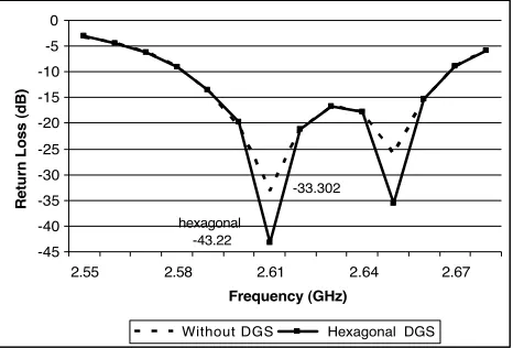
The simulation was carried out by using method of moment. Figure 2 exhibits the simulation result of the return loss of the antenna with and without DGS. The antenna with and without DGS has return loss of −43.22 dB and −33.3 dB at the resonant frequency of 2.61 GHz, respectively. The simulation result of DGS shows return loss improvement of 29.8% compared to the antenna without DGS.
-33.302
hexagonal -43.22 -45
-40 -35 -30 -25 -20 -15 -10 -5 0
2.55 2.58 2.61 2.64 2.67
Frequency (GHz)
Return Loss (dB)
Without DGS Hexagonal DGS
Figure 2. Comparison of simulated Return Loss between antenna with and without DGS antenna.
The triangular patch microstrip antenna array was designed to have circular polarization. The simulation result of the antenna with and without DGS for circular polarization shows a 3 dB axial ratio bandwidth of 2.6% and 1.9% respectively. This result shows that the antenna with DGS could increase the circular polarization bandwidth of the antenna without DGS to 10 MHz.
antenna parameters of the antenna without DGS were improved by the DGS.
3.2. Measurements
The antenna with hexagonal DGS was fabricated and measured. The DGS antenna showed characteristic improvement compared to the antenna without DGS. The measurement results demonstrated that the hexagonal DGS antenna improved the impedance matching of the antenna without DGS from minimum return loss −30.18 dB to −40.89 dB. This means there is an improvement to 35% of the minimum return loss which can increase the efficiency of the antenna. This improvement is displayed in Fig. 3. Fig. 3 shows the measured resonant frequency of the antenna with and without DGS is at 2.66 GHz.
Figure 3. Measurement result of return loss.
There is a slight shift of resonant frequency from simulation compared to measurement results. However the measured result of the antenna with and without DGS shows the same resonant frequency, therefore this measured result can be compared.
For the circular polarization of the antenna, axial ratio bandwidth was measured. The result showed an increase of 3 dB axial ratio bandwidth of 10 MHz for the DGS antenna. The antenna without DGS has axial ratio bandwidth from 2.63 GHz to 2.67 GHz and the antenna with DGS from 2.63 GHz to 2.68 GHz.
9.6 9.8 10 10.2 10.4 10.6 10.8 11 11.2
2.59 2.6 2.61 2.62 2.63 2.64 2.65 2.66 2.67 2.68 2.69 2.7 2.71
Frequency (GHz) Ga in ( d B )
Hexagonal DGS without DGS
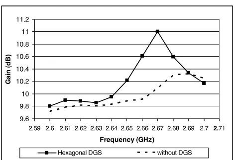
Figure 4. Comparison of measured gain between antenna with and without DGS. -60 -55 -50 -45 -40 -35 -30
2.45 2.5 2.55 2.6 2.65 2.7 2.75 2.8 2.85 2.9 2.95
Frequency (GHz) S 21 ( d B )
hexagonal DGS without DGS
Figure 5. Comparison of measured mutual coupling between antenna with and without DGS.
Figure 5 shows the comparison of measured mutual coupling between the antenna without and with DGS. The measured mutual coupling results showed that the antenna with DGS has a mutual coupling of −38 dB at the resonant frequency of 2.66 GHz, while the antenna without DGS has a mutual coupling of−35 dB. It is obvious from the result that there is a substantial mutual coupling reduction.
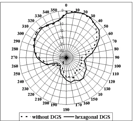
Moreover, the measured radiation patterns of the antenna in the
Figure 6. Measured E-plane radiation pattern of antenna with and without DGS.
similarity in the E-plane pattern with maximum beam tilted towards 10◦–30◦. This result agrees well with the intended design. While in Fig. 7, the antenna with DGS has a slightly higher backlobe level in the H-plane due to the presence of the hexagonal defected structure acting as a slot antenna which causes leakage field distributions. 4. CONCLUSIONS
A new DGS geometry, the double hexagonal shape have been used for two element triangular microstrip antenna array. The results demonstrated that the radiation properties of the antenna with DGS have better performance than the antenna without DGS. It is also shown that the geometry of the DGS has an influence towards the performance of the antenna characteristics.
ACKNOWLEDGMENT
This work is supported in part by the University of Indonesia under the Competitive Research Grant contract No. 240AS/DRPM-UI/NI.4/2008. The authors would like to thank Mr. Hendra Wirawan for his assistance in this research.
REFERENCES
1. Garg, R., P. Bhartia, I. Bahl, and A. Ittipibon, Microstrip Antenna Design Handbook, Artech House, Boston, London, 2001. 2. Guha, D., M. Biswas, and Y. M. M. Antar, “Microstrip patch antenna with defected ground structure for cross polarization suppression,”IEEE Antennas and Wireless Propagat. Lett., Vol. 4, 455–458, 2005.
3. Liu, H., Z. Li, X. Sun, and J. Mao, “Harmonic suppression with photonic bandgap and defected ground structure for a microstrip patch antenna,” IEEE Microw. and Wireless Compenents Lett., Vol. 15, No. 2, 55–56, Feb. 2005.
4. Chung, Y., S. Jeon, D. Ahn, J. Choi, and T. Itoh, “High isolation dual polarized patch antenna using integrated defected ground structure,” IEEE Microw. Component Lett. Vol. 14, No. 1, 4–6, Jan. 2004.
6. Yang, L., Z. Feng, F. Chen, and M. Fan, “A novel compact EBG structure and its application in microstrip antenna arrays,”IEEE MTT-SDigest, 1635–1638, 2004.
7. Salehi, M., A. Motevasselian, A. Tavakoli, and T. Heidari, “Mutual coupling reduction of microstrip antennas using defected ground structure,” 10th IEEE International Conference on Communication Systems (ICCS), 1–5, Oct. 2006.
8. Zainud-Deen, S. H., M. F. Badr, E. El-Deen, K. H. Awadalla, and H. A. Sharshar, “Microstrip antenna with defected ground plane structure as a sensor for landmines detection,”Progress In Electromagnetics Research B, Vol. 4, 27–39, 2008.