Available online:
http://edupediapublications.org/journals/index.php/IJR/
P a g e | 5729
Dynamic Analysis of High Rise Rc Structure Using
Etabs For Different Plan Configurations
Chetan P. Agrawal
1, Amey R. Khedikar
21
M-Tech Scholar, Department of Structure Engineering, TGPCET, Mohgaon, Nagpur
2Assistant Professor, Department of Structure Engineering, TGPCET, Mohgaon, Nagpur
Abstract:
High Rise RC Structure subjected to most dangerous earthquakes. It was found that main reason for failure of RC building is irregular distributions of mass, stiffness and strength or due to irregular geometrical configurations. The case study in this paper mainly emphasizes on Dynamic Analysis of High Rise RC building for different plan configurations like Rectangular-shape along with L- shape and C- shape. The analysis involves load calculation manually and analyzing the whole structure on the ETABS 9.7.1 version for dynamic analysis confirming to Indian Standard Code of Practice. These analyses are carried out by considering seismic zones IV and the behavior is assessed by taking medium soil. Post analysis of the structure, maximum story displacement, maximum story drift, story shear and maximum overturning moment are computed and then compared for all the analyzed cases.
Keywords
Regular and Irregular Structure, Response Spectrum Analysis, Time History Analysis, Seismic Response of Structure.
1. Introduction
Earthquakes are most unpredictable and devastating of all-natural disasters. Since earthquake forces are random in nature and unpredictable. They not only cause great destruction in human casualties, but also have a tremendous economic impact on the affected area.
High-Rise RC structures are a special class of structures with their own peculiar characteristics and requirements. In the modern era, most of the structures are delineated by irregular in both plan and vertical configurations. In other words, damages or loss in those structures with irregular options are over those with regular one. Thus, irregular structures would like careful structural analysis to succeed in an acceptable behavior throughout a devastating earthquake.
2. Objective of the Study
Following are the objectives of the present study;
The objective of the present work is to investigate the behavior of High-Rise RC Structures with different plan configurations under earthquake excitations using ETABS.
To analyze G+15 story high-rise RC structure with symmetrical and asymmetrical configurations.
To carry out Time History Analysis and Response Spectrum Analysis for both regular and irregular plan configurations.
To compute various seismic responses like maximum story displacement, maximum story drifts, storey shears and story overturning moment for all cases.
To compare these results for all cases by both the methods.
3. Dynamic Analysis
Though static elastic analysis is considered sufficient for smaller building, dynamic analyses shall be performed to determine the seismic force and its distribution to different levels for regular and irregular structures, as defined in clause 7.1 of IS 1893 (Part-1): 2002.
Dynamic analysis carried out using Response Spectrum Analysis and Time History Analysis.
Response Spectrum Analysis (RSA): In that method, the peak response of structure during an earthquake is obtained directly from the earthquake response, but this is quite accurate for structural design applications. The main purpose of the linear dynamic analysis is to evaluate the time variation of stresses and deformations in structures caused by arbitrary dynamic loads.
Available online:
http://edupediapublications.org/journals/index.php/IJR/
P a g e | 5730
analysis, a representative time history is required for the structure being evaluated. It is the most sophisticated analysis method available to a structural engineer. Its solution is a direct function of the earthquake ground motion selected as an input parameter for a specific building.
4. Modelling of RCC Frames
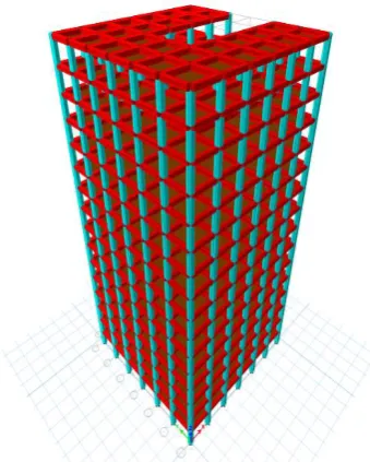
Modelling means the formation of structural body in the structure software and assigning the loads to the members as per loading consideration. Here the High-Rise RC structures having G+15 storey each are selected to model in ETABS 2016 software.
Fig. 1: Rectangular Shape 3D Model
Fig. 2: L-Shape 3D Model
Fig. 3: C-Shape 3D Model
A. Plan Details
The structure is 24m in x-direction & 24m in y-direction with columns spaced at 4m from center to center. The storey height is kept as 3m. Basically model consists of multiple bay ten storey building, each bay having width of 4m. The storey height between two floors is 3.0m.
The material properties and geometry of the model are described below;
1) Length X width : 24m X 24m 2) Number of stories : G+15 3) Support conditions : Fixed 4) Storey height : 3 m 5) Grade of concrete : M30 6) Grade of steel : Fe415 7) Size of columns : 500mm x 500mm 8) Size of beams : 300mm x 500mm 9) Slab thickness : 150mm 10) Height of parapet wall : 1m 11) Thickness of main wall : 230mm 12) Thickness of parapet wall : 115mm 13) Density of Concrete, ϒ’c : 25KN/m3
14) Density of Brick wall, ϒ’brick : 20KN/m3
B. Loading Details
The structures are acted upon by different loads such as dead load (DL), Live load and Earthquake load (EL).
1. Self-weight of the structure comprises of the weight of the beams, columns and slab of the structure.
Available online:
http://edupediapublications.org/journals/index.php/IJR/
P a g e | 5731
a) Wall load: weight unit of brick masonry X thickness of wall X height of the wall
= 20 KN/m3 X 0.23m X 3m= 13.8 KN/m b) Parapet Wall load: weight unit of brick masonry X thickness of wall X height of the wall
= 20 KN/m3 X 0.115m X 1m= 2.3 KN/m 3. Live load consist of Floor load which is taken as 4KN/m2 and Roof load as 2 KN/m2, according to IS
875 (Part 2).
4. Seismic Load: Earthquake loads have been defined and assigned on the building as per IS 1893:2002 (Part-I).
▪ Seismic zone: IV (z = 0.24) ▪ Soil type: Medium soil ▪ Importance factor: 1
▪ Response reduction factor: 5 (SMRF) ▪ Damping: 5%
5. Results and Discussion
After analysis the results are being illustrated using the graphs shown below which explain the structural behavior of both the structures (regular and irregular) in terms of maximum story displacement, maximum story drift, story shear and maximum overturning moment were computed each for all cases.
Fig. 4: Maximum Story Displacement by RSA
Fig. 5: Maximum Story Displacement by THA
Above Fig. 4 – Fig. 5 shows that story displacement is linearly increasing from bottom to top for both the structures and is more for irregular structure. According to Codal provision, maximum
or permissible story displacement should be equal to or less than 0.4% of total building height. Hence here the maximum permissible story displacement = ((0.4 / 100) x 48000) = 192 mm.
Difference between the story displacement value by both the analysis become large for higher stories. Displacement in rectangular shape building is less compare to other shape of the building.
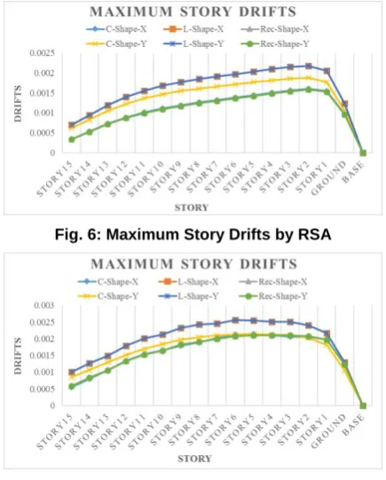
Fig. 6: Maximum Story Drifts by RSA
Fig. 7: Maximum Story Drifts by THA
Above Fig. 6 – Fig. 7 shows the variation of story drift between different floor of all cases. Here the story drift varies in a similar manner for all configurations. The maximum story drift permitted is 0.004 times the story height i.e. 0.004 x 3 = 0.012 m for all story. Drift in rectangular shape building is less compare to other shape of the building.
Available online:
http://edupediapublications.org/journals/index.php/IJR/
P a g e | 5732
Fig. 8: Story Shears by RSA
Fig. 9: Story Shears by THA
Above Fig. 8 – Fig. 9 shows the Base Shear for all story for different shape of the building. It has been concluded that the story shear tends to decrease with the increase in height of the story. For all the structures it is highest at bottom and it decreases linearly towards top. L- shape building has less story shear compare to other shape of the building. The storey shear force was found to be maximum for the first storey and it decreased to a minimum in the top storey in all cases.
Fig. 10: Story Overturning Moment by RSA
Fig. 11: Story Overturning Moment by THA
Above Fig. 10 – Fig. 11 shows the variation of storey overturning moments at different floor levels of both the structures. Story overturning moment
decreases with increase in height of the story for all cases.
6. Conclusions
On the basis of the analytical results of the study, the following conclusions were drawn:
The plan configuration of structure has significant impact on the seismic response of structure in terms of maximum story displacement, maximum story drifts, story shears and story overturning moment. Irregular shape building undergoes more deformation and hence regular shape building must be preferred.
Irregular shape buildings are severely affected during earthquakes especially in high seismic zones.
Comparison of all the parameters are made which can give us better idea about the behaviour of the building is rectangular shape is always better of C-shape and L-shape.
Top story displacement by Time History Analysis is higher than the story displacement by Response Spectrum Analysis.
Story shear by Time History Analysis is more than the story shear by Response Spectrum Analysis.
Overturning moments by Time History Analysis is more than the overturning moment by Response Spectrum Analysis.
Equivalent Static Analysis is not sufficient when buildings are irregular buildings and it is essential to provide Dynamic analysis due to non-linear distribution of force.From the results it is recommended that Time History Analysis should be performed as it predicts the structural response more accurately than the Response Spectrum Analysis. For dynamic analysis, Time History Analysis is best suited compare to Response Spectrum Analysis.
The analysis proves that irregularities are harmful for the structures and it is important to have simpler and regular shapes of frames as well as uniform load distribution around the building. Therefore, as far as possible irregularities in a building must be avoided. But, if irregularities have to be introduced for any reason, they must be designed properly taking care of their dynamic behavior.
7. Acknowledgements
Available online:
http://edupediapublications.org/journals/index.php/IJR/
P a g e | 5733
support throughout my studies. Their technical and editorial advice was essential for the completion of this dissertation. We extend our heartfelt thanks to our worthy faculty.
As in this heading, they should be Times 11-point boldface, initially capitalized, flush left, with one blank line before, and one after.
7.1.1.Third-order Headings. Third-order headings, as in this paragraph, are discouraged. However, if you must use them, use 10-point Times, boldface, initially capitalized, flush left, preceded by one blank line, followed by a period and your text on the same line.
This work was supported in part by a grant from the National Science Foundation.
Contribution of others who might have given suggestions or review comments.
8. References
i. Mario De Stefano, Barbara Pintucchi (2008), ‘A
Review of Research on Seismic Behaviour of Irregular Building Structures Since 2002’, Bulletin of Earthquake Engineering, May 2008, Volume 6, Issue 2, PP 285-308.
ii. Sadjadi R., Kianoush M. R., Talebi S., (2007),
‘Seismic Performance of Reinforced Concrete
Moment Resisting Frames’, Engineering Structures,
Volume 29, Issue 9, September 2007, 2365–2380.
iii. Athanassiadou C. J., (2008), ‘Seismic Performance of
R/C Plane Frames Irregular in Elevation’, Engineering Structures, 30 (2008):1250–1261.
iv. Amin Alavi and P. Srinivasa Rao (2013), ‘Effect of
Plan Irregular RC Buildings in High Seismic Zone’, Australian Journal of Basic and Applied Sciences, 7(13) November 2013, Pages: 1-6.
v. Albert Philip, S. Elavenil (2017), ‘Seismic Analysis of
High Rise Buildings with Plan Irregularity’, International Journal of Civil Engineering and Technology (IJCIET), Volume 8, Issue 4, April 2017, PP. 1365–1375.
vi. Abhay Guleria (2014), ‘Structural Analysis of a
Multi-Storeyed Building using ETABS for different
Plan Configurations’, International Journal of
Engineering Research & Technology (IJRET), Vol. 3 Issue 5, May 2014.
vii. Anil Kumar K. (2016), ‘Analysis of Behaviour of a
High-Rise Building with Various Plan Configurations Under the Influence of Seismic Forces’, International Journal of Innovative Research in Science and Engineering (IJIRSE), Volume 2 Issue 6 – June 2016.
viii. Agrawal Pankaj and Shrikhande Manish, (2010),
“Earthquake Resistant Design of Structures”, PHI
Learning Private Limited, New Delhi.
ix. Duggal S. K., (2011), “Earthquake Resistant Design
of Structures”, Sixth Edition, New Delhi, Oxford University Press.
x. Chopra A. K., (2012), "Dynamics of Structures:
Theory and Applications to Earthquake Engineering", Fourth Edition, Prentice Hall.
xi. ETABS Non-Linear Version 9.7.1 and Design
Manuals.
xii. IS 875 - 1987 (Part 1), Code of Practice for Design
Loads (Other Than Earthquake) for Buildings and Structures, Part 1 Dead Loads (Second Revision), Bureau of Indian Standards, New Delhi, India.
xiii. IS 875 - 1987 (Part 2), Code of Practice for Design
Loads (Other Than Earthquake) for Buildings and Structures, Part 2 Imposed Loads (Second Revision), Bureau of Indian Standards, New Delhi, India.
xiv. IS 1893: 2002 (Part-I), Criteria for Earthquake
Resistant Design of Structures, Part I General Provisions and Buildings (Fifth Revision), Bureau of Indian Standards, New Delhi, India.
xv. IS 456: 2000, Plain and Reinforcement Concrete –
Code of Practice (Fourth Revision), Bureau of Indian Standards, New Delhi, India.
9. Biographies
Chetan P Agrawal
BE [Civil Engineering] M-Tech Scholar TGPCET, Nagpur
08668371361, 08149329260
Amey R. Khedikar
BE [CE], M-Tech [SE] Assistant Professor TGPCET, Nagpur