Design of Multiband Quad-Rectangular Shaped Microstrip Antenna
for Wireless Applications
Abhishek K. Saroj*, Mohd. G. Siddiqui, Mukesh Kumar, and Jamshed A. Ansari
Abstract—This paper presents a Quad-Rectangular Shaped Microstrip Antenna (QRSMA) fed by a single microstrip line feed. QRSMA having different frequency bands is designed to be applied to L (1–2 GHz), S (2–4 GHz) and C (4–8 GHz) bands applications. QRSMA is loaded with a single square patch and 4 rectangular patches. The patches are loaded using a flame retardant substrate (Fr-4). The patches are connected with 1 mm width of copper (Cu) strip-line. Thus the proposed design of patches and width is responsible for desired multiband operations. The antenna resonates at frequencies
f1 = 1.074, f2 = 3.119, f3 = 4.089, f4 = 5.683 and f5 = 6.514 GHz. Thus, the antenna is useful in
the L, S and C band applications. Compared to other antenna designs, the proposed antenna exhibits multiband performance, size reduction and is economical. It also realizes tunability of frequencies having stable radiation pattern with compact electrical size. The paper analyses the simulated and experimental results. Various cases of QRSMA performances are also compared in this paper.
1. INTRODUCTION
In recent years, microstrip antennas are appropriate candidates to meet the mentioned requirement, so that they can be used in broadband range of applications such as radar, navigation, satellite applications, GPS, due to ease of fabrication and low manufacturing cost. For an antenna with multiple operating frequencies, the adaptability to different scenarios in wireless communication and radar systems is a prerequisite for covering multiband applications. Many techniques have been reported in the past to obtain multiband with notches and slots. A number of papers on multiband antennas have been presented in the literature. In [1], a triple-band antenna is designed, and it surpasses dual-band antennas to meet the requirement of modern wireless communication systems. Several microstrip slot antennas that possess low profile, conformal feature and ease of fabrication [2–4] are studied. A microstrip line fed compact triple-band antenna for WLAN/WiMAX application is reported in [5], and a multi-resonator loaded antenna suitable for multiband operation is presented in [6]. There are many antenna designs that utilize microstrip line for feeding purpose [7–9]. A miniaturized multiband antenna for frequencies in S, C and X bands is also reported for military and satellites applications [10]. Recently, it has been shown that multiband resonance can be achieved by using coaxial feeding in disc-patch antenna of C-shaped slots [11–13]. For mobile communication systems such as mobile, laptops, tablets and various small portable devices, a reduced size antenna is required as seen in the case of a compact antenna with multiple narrow slits for multiband operation [14]. It is also seen that creating slots on the patch can be a simple approach for designing a multiband microstrip antenna [15].
Here we propose a compact notch and slot loaded microstrip patch antenna, which exhibits multiband behaviour. The antenna also achieves significant reduction in size of about 58% with good impedance bandwidth. Resonance frequency is tuned by changing the dimensions of notches and slots. The parametric study is carried out, and various parameters are calculated as the function of the
Received 10 July 2017, Accepted 9 August 2017, Scheduled 22 August 2017
* Corresponding author: Abhishek Kumar Saroj ([email protected]).
frequency. The QRSMA exhibits balanced performance in simulated and experimental results of various frequency bands, operated at central frequencies of f1 = 1.074, f2 = 3.119, f3 = 4.089, f4= 5.683 and
f5 = 6.514 GHz.
2. DESIGN AND ANALYSIS OF QUAD-RECTANGULAR SHAPED MICROSTRIP ANTENNA
2.1. Antenna Structure
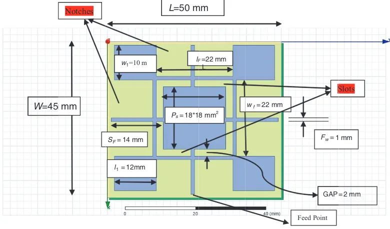
The geometrical configuration of Quad-Rectangular Shaped Microstrip Antenna (QRSMA) is shown in Fig. 1. The antenna comprises a central square patch of dimension 18∗18 mm2. This central square patch is connected to other four rectangular patches of dimension 12∗10 mm2 each. All patches are connected through 1 mm width strip-lines as shown in Fig. 1.
W=45mmm Notches
w1=10 m
l1= 12mm SF= 14 mm
L=50 m
P s= 18*1 m
L
l =22 mm
8 mm2
w f= 22 mm
1
GAP
Feed Point
S
mm
= 2 mm
Slots F
Fw=
Figure 1. Geometrical configuration of proposed antenna.
Table 1. Dimensions of proposed antenna.
Length of Ground(L) 50 mm
Width of Ground(W) 45 mm
Length of Rectangle patches (l1) 12 mm Width of Rectangle patches (w1) 10 mm
Square patch Size(Ps) 18∗18 mm2
Length of feed line (lF) 22 mm
Width of feed line(wf) 22 mm
Side feed line length (SF) 14 mm
Gap between Square patch and feed line 2 mm
Feed line Width (Fw) 1 mm
Thickness of Substrate(h) 1.6 mm
The patch antenna is printed on an FR-4 dielectric substrate of relative permittivity 4.4 and thickness 1.6 mm. The optimal parameters of the proposed antenna are as follows: length L= 50 mm, width W = 45 mm, and the gap between square patch and connected feed-line 2 mm. Detailed description of geometry is given in Table 1. In the proposed antenna, an edge mounted SMA connector is used with strip-line feed of 50 ohms impedance, which is shown in Fig. 1 and Fig. 2.
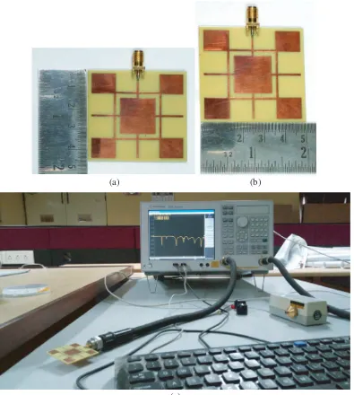
(a) (b)
(c)
Figure 2. (a), (b) Radiating patch. (c) Testing arrangement.
The actual fabricated radiating patch and ground plane of the proposed antenna are shown in Fig. 2.
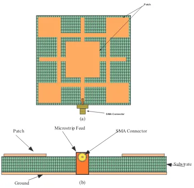
Three-dimensional top view and front view of proposed antenna are shown in Fig. 3.
Patch
SMA Connector
Substrate
Ground
Patch Microstrip Feed SMA Connector
(a)
(b)
Figure 3. (a) Top view. (b) Front view.
2.2. Results and Discussion
All comparative studies are performed using HFSS software. Analysing all the results, we find that it operates at five distinct resonant frequencies with acceptable performance. The resonance frequencies of proposed antenna are measured by vector analyser Agilent Technologies E5071C, and simulations are performed by HFSS simulator. Photographs of the fabricated antenna are shown in Fig. 2(a) & Fig. 2(b), and the setup for measuring return loss and VSWR using vector analyser are shown in Fig. 2(c). Comparisons of simulated and measured results are shown in Table 2 that meets the−10 dB requirement in most of the resonating frequencies. It shows that the simulated and measured results are in good agreement.
Table 2. Comparisons of simulated and measured reflection coefficient of the proposed antenna.
Simulated Measured Bands Frequency (GHz) Return Loss (dB) VSWR Frequency (GHz) Return Loss (dB) VSWR
1.074 −27.22 1.958 1.085 −24.22 1.374 L [1–2] GHz
3.119 −22.60 3.675 3.122 −16.41 1.307 S [2–4] GHz
4.089 −16.81 2.014 4.127 −15.54 1.412 C [4–8] GHz
5.683 −17.95 1.964 5.728 −14.71 1.449 C [4–8] GHz
6.514 −25.21 2.014 6.582 −23.11 1.416 C [4–8] GHz
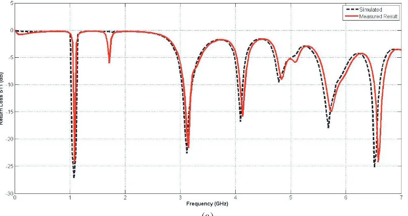
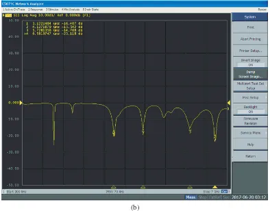
Figure 5(a) shows the simulated and experimental graphs of reflection coefficient (S11) with respect
to frequency, and Fig. 5(b) shows the experimental result of reflection coefficient with respect to frequency in vector network analyser (VNA).
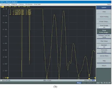
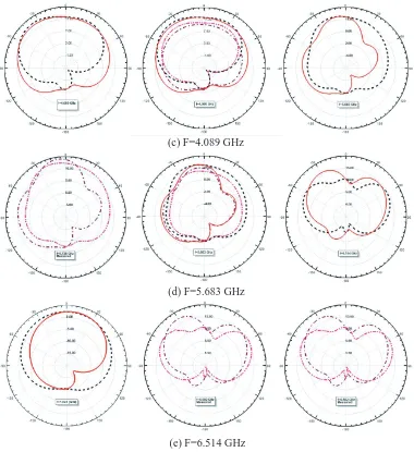
Figure 6(a) shows the comparison between simulated and experimental VSWRs (voltage standing wave ratio), and Fig. 6(b) shows measured VSWR in vector network analyser with respect to frequency. The proposed antenna has the capability of impedance matching at different resonating frequencies using combinations of multiple slots and notches. Fig. 7 shows the simulated, measured and comparison radiation patterns of the antenna at f1 = 1.074, f2 = 3.119, f3 = 4.089,f4= 5.683, f5= 6.514 GHz.
It is observed that the characteristics of the proposed antenna match the simulation and measured
(b)
Figure 5. (a) Comparison of simulated and measured reflection coefficient (S11) vs frequency of the
proposed antenna. (b) Measured reflection coefficient in vector network analyzer (VNA).
data. In simulation, antenna operates atf1 = 1.074,f2 = 3.119,f3 = 4.089,f4= 5.683,f5= 6.514 GHz,
but in experiment, it operates at f1 = 1.085, f2 = 3.122, f3 = 4.127, f4 = 5.728, f5 = 6.582 GHz. In
the proposed QRSMA, a small variation exists due to environmental condition and manufacturing technicalities. QRSMA resonates at f1 = 1.074 GHz which is suitable for L-band applications,
(b)
Figure 6. (a) Comparison of simulated and experimental VSWRs vs. frequency of proposed antenna. (b) Measured VSWR vs. frequency in vector network analyser.
Simulated Comparision Measured
(a) F=1.074 GHz
(c) F=4.089 GHz
(d) F=5.683 GHz
(e) F=6.514 GHz
Figure 7. Simulated, measured and compared radiation pattern. (a) f1 = 1.074. (b) f2 = 3.119. (c)
f3 = 4.089. (d)f4 = 5.683. (e) f5= 6.514 GHz.
f2 = 3.119 GHz suitable for S-band applications andf3 = 4.089, f4 = 5.683 & f5= 6.514 GHz suitable
for C-band applications. Moreover, the proposed antenna has several advantages such as small size, good impedance matching and radiation pattern. This antenna is capable of satisfying the requirement of wireless communication systems.
3. CONCLUSION
In this article, a Quad-Rectangular Shaped Microstrip Antenna (QRSMA) has been designed, fabricated and simulated using HFSS software and tested by Agilent vector analyser model no. E5071C. In the proposed antenna, multiband behaviour is obtained with the introduction of slots and notches. The QRSMA resonates atf1 = 1.074 GHz which is suitable for L-band applications,f2 = 3.119 GHz suitable
for S-band applications andf3 = 4.089,f4= 5.683 &f5= 6.514 GHz suitable for C-band applications.
REFERENCES
1. Kumar, P., S. Dwari, and P. S. Pakariya, “Tripple-band microstrip antenna for wireless application,”
Springer Wireless Pers. Commun., Springer Science+Business Media, New York, 2017.
2. Jan, J. Y. and J. W. Su, “Bandwidth enhancement of a printed wide-slot antenna with a rotated slot,” IEEE Transactions on Antennas and Propagation, Vol. 53, 2111–2114, 2005.
3. Liu, Y. F., K. L. Lau, Q. Xue, and C. H. Chen, “Experimental studies of printed wide-slot antenna for wide-band applications,” IEEE Antennas Wirel. Propag. Lett., Vol. 3, 273–275, 2004.
4. Chen, W.-S. and K.-Y. Ku, “Band-rejected design of printed open slot antenna for WLAN/WiMAX operation,” IEEE Transactions on Antennas and Propagation, Vol. 56, No. 4, 1163–1169, 2008. 5. Thomas, K. G. and M. Sreenivasan, “Compact triple band antenna for WLAN/WiMAX
applications,” Electronics Letters, Vol. 45, No. 16, July 30, 2009.
6. Hu, W., Y. Z. Yin, X. Yang, and P. Fei, “Compact multiresonator-loaded planar antenna for multiband operation,” IEEE Antennas and Wireless Propagation Letters, Vol. 61, No. 5, 2838– 2841, 2013.
7. Liu, C. S., C. N. Chiu, and S. M. Deng, “A compact disc-slit monopole antenna for mobile devices,”
IEEE Antennas and Wireless Propagation Letters, Vol. 7, 251–254, 2008.
8. Sarin, V. P., V. Deepu, C. K. Aanandan, P. Mohanan, and K. Vasudevan, “Wideband printed microstrip antenna for wireless communications,” IEEE Antennas and Wireless Propagation
Letters, Vol. 8, 779–781, 2009.
9. Liu, W. C., M. Ghavami, and W. C. Chung, “Triple-frequency meandered monopole antenna with shorted parasitic strips for wireless application,” IET Journal of Microwave, Antennas &
Propagation, Vol. 3, 1110–1117, 2009.
10. Boukarkar, A., X.-Q. Lin, Y. Jiang, and Y.-Q. Yu, “Miniaturized single-feed multi-band patch antennas,”IEEE Transactions on Antennas and Propagation, Vol. 65, No. 2, 850–854, 2017. 11. Ansari, J. A., S. Verma, and A. Singh, “Design and investigation of disk patch antenna with
quard c-slots for multiband operations,”Hindawi International Journal of Microwave Science and
Technology, Vol. 2014, article id 504363, 2014.
12. Gupta, S. K., A. Sharma, B. K. Kanaijia, S. Rudra, R. R. Mishra, and G. P. Pandey, “Orthogonal slit cut stacked circular patch microstrip antenna for multiband operations,”Microwave and Optical
Technology Letters, Vol. 55, No. 4, 873–882, 2013.
13. Sun, X., G. Zeng, H. C. Yang, Y. Li, X. J. Liao, and L. Wang, “Design of an edge-fed quad-band slot antenna for GPS/WiMax/WLAN applications,”Progress in Electromagnetic Research Letters, Vol. 28, 111–120, 2012.
14. Verma, S., J. A. Ansari, and M. K. Verma, “A novel compact multi-band microstrip antenna with multiband narrow slits,” Microwave and Optical Technology Letters, Vol. 55, No. 6, 1196–1198, 2013.