67
Characterization and Analysis of Frequency Modulated
Transmitter
Isizoh A. N.
1,
Nwobodo H. N.
2, Asogwa T. C.
3,
Nwobodo Lois O.
4, Okide S. O.
5Dept. of Electronic and Computer Engineering1, Dept. of Computer Science5 Nnamdi Azikiwe University, Awka, Nigeria1, 5
E-mail: [email protected], [email protected] Dept. of Computer Engineering2,3,4,
Enugu State University of Science and Technology, Enugu, Nigeria2,3,4 Email: [email protected],[email protected], [email protected]
Abstract-
It Is A General knowledge that transmitter plays an important role in voice communication-a domain of telecommunications. With the use of a transmitter, audio signals can be processed for better transmission over long distance by means of electromagnetic waves. This paper thus presents a frequency modulated (FM) transmitter. It consists of the pre-amplifier which amplifies the audio picked up by a microphone needed to modulate the resonant frequency of a tank circuit, comprising a five turn coil and a capacitor. The FM signal is converted to an electromagnetic wave and transmitted via an antenna. The emphasis is to keep the carrier’s amplitude constant, while its frequency is varied in accordance with the amplitude variations of the audio signal. By using transistors and few passive components, the transmitter can deliver signals to an appreciable distance.Keywords:
Antenna, frequency, modulation, oscillator, transmitter.1. INTRODUCTION
A transmitter is that part of electronic equipment which generates a carrier wave, modulates it with intelligence, amplifies it and radiates it as electromagnetic waves from an antenna. The ability of the transmitter to process audio signal for better transmission over a long distance by means of electromagnetic waves makes it a vital tool in communication [1].
There are many types of transmitters and numerous variation of each type. Each type is named according to the modulation used. Such modulation schemes include amplitude modulation, frequency modulation and phase modulation. By the process of modulation, some sort of intelligent information is superimposed on the radio waves by varying some features of the wave in accordance with the information to be transmitted. Here, a low frequency audio signal is superimposed on a high frequency RF carrier signal.
Radio frequencies generated by oscillators and sent out as radio waves from transmitting aerials are by themselves messengers.
The oscillator of a radio transmitter produces a sine wave carrier signal.
e(t) = EPsin (ω(t) + θ) ……….. (Eq. 1) Where:
Ep is the amplitude
ω(t) is the angular frequency
θ is the phase angle
Ep, ω(t), and θ are the only three parameters which together determine the value e(t) at any given instant. This equation applies to the un-modulated carrier wave. Information may be added to the wave by altering the value (i.e. modulating) of any one of the three parameters: amplitude, (Ep), frequency (ω) or phase (θ) in conformity with variations in the magnitude of the modulating signal.
Basic Block Diagram of FM Transmitter
Mic
Fig. 1: FM Transmitter Block Diagram
RF Oscillator
Balanced modulator
Side band Filter
Power Amplifier
Low-Pass Filter
68 The block diagram of the system as shown in figure 1
has the following units as explain below.
AF Amplifier
Microphones convert the spoken voice into an electrical signal by using a small diaphragm connected to a coil of wire in a magnetic field. The movement of the coil in the field causes a current to flow. However the amount of current generated by this method is too small and so the microphone is fed into an Audio Amplifier which amplifies the microphone output to a level that can be used in the modulation stage [5].
RF Oscillator
There are basically two different types, a crystal oscillator and a variable frequency oscillator, with the later employing a tuned circuit. Either type may be used in an RF oscillator. The crystal oscillator is stable and relatively insensitive to temperature and mechanical fluctuations. However, it is fixed to one frequency and therefore cannot be used for continuous tuning. By contrast the variable Frequency Oscillator can cover a wide range of frequencies but it is often temperature sensitive and is
best housed in a rigid mechanical box to prevent movement and to screen it from RF.
Modulator
Modulation is basically the process of mixing two frequencies. When in reverse bias, the varicap diode has a capacitance across it which is proportional to the magnitude of the reverse bias applied to it. As the reverse bias increases, the capacitance decreases and the frequency increases. The sine wave base band voltage has the effect of varying the capacitance of the varator up and down from the level set by a fixed reverse voltage bias. As the base band peaks, the varactor’s capacitance is at a minimum and the overall frequency will increase. In a balanced modulator (or mixer) there are only two outputs, the upper and lower sideband [5]. A balanced modulator effectively removes or suppresses the carrier.
Sideband filter
This is narrow band pass filler, so narrow that it is only possible for one of the two sidebands to pass. Thus only one sideband is passed to the RF power amplifier and transmitted. The graphical representations are shown in figures (2a) and 2(b).
Fig. 2(a): Band-Pass filter Fig. 2(b): SSB (FM) Bandwidth
Power Amplifier
This is simply an amplifier for RF and boosts the low internal signal immediately prior to sending the signal to the antenna.
Low-Pass Filter
The purpose of a low pass filter is to prevent spurious harmonics of the fundamental (carrier) frequency escaping from the equipment (transmitter). This prevents the harmonics (multiples of the fundamental or carrier frequency) being sent to the antenna. In this transmitter, only one sideband is required for effective communication, because both sidebands contain the same information.
Transmission Lines and Antenna
The final stage of any transmitter is the antenna. This is where the resultant FM signal is converted to
electromagnetic waves which are radiated into the atmosphere. The purpose of any transmission line is to transfer power between a source and a load. To transfer the maximum power form a generator into a load, the impedance of the load and the internal Impedance of the generator and any intervening transmission line must equal.
Power Supply Unit
A power supply unit is the basic unit in any electronic equipment. It supplies the voltage needed for the operation of the appliance. A power supply unit increases or reduces the main voltage and then converts it form AC to steady DC so that it can be used in a range of electronic circuits. Power supply unit comprises the transformer, a rectifier, a smoothing/ filtering circuit and a regulator/
S
ig
n
al
P
o
w
er
(
d Carrier Removed by
Modulator
Lower Sideband Removed by filter
V
F
69 stabilizing circuit. The block diagram of the power supply unit is shown in figure 3.
Fig. 3: Block Diagram of the Power Supply Unit
Transformer: The basic function is to transform AC energy from one coil to another without having a DC connection between the two ends. Transformers have the ability to transform voltage and current to higher or lower levels. The ratio of primary to secondary turns determines a transformer voltage ratio.
Rectifier: Rectifier change AC into pulsating DC by eliminating the negative half cycles of the alternating voltage. Thus only a series of sine wave pulsations of positive polarity remain. All rectifiers must provide a substantially one-way path for electric current that is conduction must take place primarily in one direction only. A transformer is used to step down the mains voltage, which is then placed across the diodes [2]. Rectifier diodes are used in power supplies to convert AC to DC.
Filtering/ Smoothing: Although the rectifier circuits deliver an output voltage that always has the same polarity, this voltage is not suitable as DC supply because of pulsations in amplitude or ripple of the output voltage. The pulsations must be smoothed out before any application. Filter networks consisting of inductors and capacitors obtain the required smoothing action.
Regulation: It is desirable for the output voltage/current to remain constant regardless of load current variations. A regulator is a device, which maintains constant output voltage or current regardless of input voltage or output current requirement.
2. ANALYSIS
By frequency modulation, the instantaneous output frequency of a transmitter is varied in accordance with the modulating signal. Recall that the equation for a sine wave is as follows:
e(t) = EPsin (ω(t) + θ)
Frequency modulation here is realized by varying ω in accordance with the modulating signal or message. One can also vary θ and Ep to obtain other modulation methods which are phase modulation (PM) and amplitude modulation (AM) respectively [2].
FM Generation
The most common method used to generate FM is called direct FM. This method uses an active device called varactor diode which acts like a capacitor when reverse biased. Hence the varactor or varicap diode changes its capacitance in response to the p.d applied to it. When the varicap diode is fed with audio input-signal voltage, changes in the voltage will result in changes in the p.d across the varicap. Changes in the p.d in the varicap also alter the resonant frequency of the RF oscillator.
It is also possible to obtain FM from PM as shown in figure 4; but most present-day FM systems do not generate FM by this method. This process of generating FM is known as indirect FM.
Fig. 4: Generation of FM from PM (indirect FM)
Frequency Modulation (FM) Versus Phase Modulation (PM).
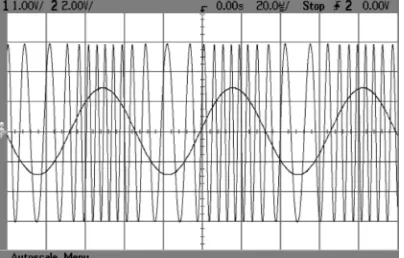
Frequency modulation and phase modulation are both forms of angle modulation [1]. However if the instantaneous frequency of the signal is directly proportional to the amplitude of the input signal, it is FM as shown in figure 5.
Audio input
f
c (2)FM out
Phase Modulator (PM)
x x x x
Transformer DC
output
Rectifier Smoothing
Circuit
[image:3.595.306.527.425.497.2]70 Fig. 5: FM signal with the modulating signal
On the other hand, if the instantaneous ‘phase’ of the signal is proportional to the amplitude of the input signal, it is PM. In other words, the transmitter output frequency is at the rest frequency when the input signal is at either its most positive or most negative as shown in figure 6.
Fig. 6: Phase-modulated wave and the modulating wave
Modulation Index of an FM Wave
The modulation index (mf) is the ratio of the amount of frequency deviation to the audio modulating frequency.
mf = Fdev …….. (Eq. 2)
fm
where Fdev = frequency deviation, fm = modulating frequency
For radio voice communication fm would be between 100 Hz and 3 KHz maximum [6]. The modulation index (mf) has no unit. Also, the amount of frequency deviation a signal experiences is a measure of the change in transmitter output frequency from the rest frequency defined as output frequency with no modulating signal applied. FCC limits FM broadcast-band transmitters to a maximum frequency deviation of ± 75 KHz [6].
Deviation Ratio
The modulation index is called the deviation ratio when the frequency of the modulating audio is at its highest. The practical implementation of FM communication systems in a limited bandwidth-channel environment, such as cellular radio, requires a limitation upon the maximum frequency deviation to prevent adjacent channel interference.
Percentage of Modulation
In equation form, the percentage of modulation is given by:
% modulation = Fdev x 100% ….. (Eq. 3)
Fdev(max)
where Fdev(max) = ± 75 KHz
Bessel Functions and their Relationship to FM
Bessel function identities allow us to determine the frequency components of an FM wave. By frequency component, we mean the side bands/frequencies generated.
[image:4.595.73.273.117.256.2]For specific values of the index of modulation, one can use Bessel-function tables to determine the side band amplitude distribution and the signal bandwidth.
Table 1: The Bessel functions
mf J0 J1 J2 J3 J4 J5 J6 J7 J8 J9 J10 J11 J12 J13 J14
0.00 0
1.00
0.25 0
0.98 0.12 0.01
0.50 0
0.94 0.24 0.03
1.00 0
[image:4.595.72.274.355.484.2]71 1.50
0
0.51 0.56 0.23 0.06 0.01
2.00 0
0.22 0.58 0.35 0.13 0.03 0.01
2.40 5
0.00 0.52 0.43 0.20 0.06 0.02
3.00 0
-0.26
0.34 0.49 0.31 0.13 0.04 0.01
4.00 0
-0.46
-0.07 0.36 0.43 0.28 0.13 0.05 0.0 2 5.00
0 -0.18
-0.33 0.05 0.36 0.39 0.26 0.13 0.0 5 0.0 2 0.0 1 7.00 0 -0.30
0.00 -0.30
-0.17
0.16 0.35 0.34 0.2 3 0.1 3 0.0 6 0.0 2 0.0 1 10.0 0 -0.25
0.04 0.25 0.06 -0.22 -0.23 -0.01 0.2 2 0.3 2 0.2 9 0.2 1 0.1 2 0.0 6 0.0 3 0.0 1
FM Signal Bandwidth using Bessel Function When a carrier (fc) is frequency modulated by a signal (fm), then theoretically, an infinite number of side bands will be produced on each side of the carrier. The distance between each of the side bands is equal to the frequency of the modulating signal (fm). The amplitude between each of the side bands is dependent upon the modulation index mf as can be seen from the Bessel Function table in Table 1. If a transmitter gives a peak deviation of 3 KHz, and that the modulating audio frequency is 3 KHz, then the spectrum of this wave can be constructed with the aid of the Bessel functions.
It is shown that the modulation index (mf) of this wave = 1 because
mf = Fdev = 3 KHz = 1
fm 3 KHz
By consulting a table of Bessel functions, we see that the voltage amplitude of the carrier for a modulation index of 1 is 0.77 and the first two pairs of side bands have amplitudes of 0.44 and 0.11 respectively. The third pair of sideband with amplitude 0.02 is considered insignificant since its voltage amplitude is less than 10% of the un-modulated carrier amplitude. Then there are 2(mf +1) or 4 significant side bands present in the transmitted wave (two each side of the carrier) each spaced apart by (fm) or 3 KHz as shown in the figure below. So that the bandwidth becomes: 2 (∆f + fm)
Where ∆f = deviation fm=modulating
FM Power Relations using Bessel Function
With the aid of a table of Bessel functions, it can be shown that the total power of an FM wave remains
constant. Recall that a table of Bessel functions gives the relative voltage amplitude for the carrier and each pair of side bands. Also since the power is directly proportional to the square of the voltage, the relative power amplitude of the carrier and its side bands can be found by squaring each value bsted in the table. In addition, since the total power in an FM wave remains constant, the sum of the squares of the values in the Bessel table should equal 1 for any particular modulation index.
Noise Effect on FM
Electrical variations encountered by the FM signal will cause distortion by “jittering” the frequency of the FM signal. Also, noise can make radio reception less readable and unpleasant. The noise is greatest in frequencies above 3KHz. The high frequency noise causes interference to the already weak high frequency voice. As the modulating frequency increases, the effect of noise increases.
Pre-Emphasis and De-Emphasis
FM communication systems have incorporated a noise-combating system of pre-emphasis and de-emphasis. A pre-emphasis network in the transmitter accentuates (boosts) the audio frequencies above 1 KHz [6], thus improving the signal-to-noise ratio at the receiver. Pre-emphasis gives added amplitude to the higher modulating frequencies prior to modulation. This added amplitude will serve to make the higher frequencies more immune to noise by increasing their index of modulation. Pre-emphasis are obtained by using simple high-pass audio filters (HPFS).
72 1 KHz in the FM receiver. De-emphasis (in the
receiver) attenuates the high audio frequencies in the receiver to restore the original audio as closely as possible. De-emphasis is achieved at the receiver using a Low Pass Filter (LPF) [7].
3. CONCLUSION
The FM transmitter described in this paper transmits signals which is frequency modulated. This means that the carrier’s amplitude remains constant and its frequency varies according to the amplitude variations of the audio signal. Since the transmitted FM signal does not rely on amplitude changes to send information, we can conclude that the FM system is immune to noise and interference than the AM (Amplitude Modulated) system. Frequency modulation is also used as a more commercial tool than other modulation methods.
However, with the aid of a table of Bessel functions, it can be shown that the total power of an FM wave remains constant.
REFERENCES
[1] Wole Modibbo S. (2012), “Fundamentals of
Communication Engineering”, Second Edition, Rerenya Printing and Publishing Co., Ibadan, Nigeria.[2] Kennedy, D. (2009), “Electronic Communication Systems”, Mc Graw-Hill, New Delhi.
[3] Theraja, A.K., and Theraja, B.L. (2010), “Electrical Technology”, S. Chand and Company Ltd., India.
[4] Ezenwa Emengini and Oboh Eteh (2012), “Electronics Engineering: Theory and Practice”, Amaka Dreams Publisher, Awka.
[5] Brinley, K., and Carr J. (2012), “Newness Electronics Engineer’s Pocket book”, Butterworth-Heinemann, Oxford. England. [6] William H. Hayt and John A. Buck (2006),
“Engineering Electromagnetics”, Seven edition, Mc Graw-Hill, New Delhi.
[7] Okondu J.B. (2011),”Radio Engineering”, Agbab Printers and Publishers, Lagos, Nigeria.