Technology (IJRASET)
Analysis & Implementation of Frequency
Modulation in Order to make a Frequency
Transmitter
Md. Tanjil Sarker1, Md.Timur Rahman2, Mustakim Al Muntasirur Rahman3, Md. Kamruzzaman4, Md. Nesar Uddin5, Vidyut Kumar Sarker6, Prof. Dr.Saiful Islam7
1,2,3,4
Department of Electrical & Electronics Engineering, Bangladesh University, Dhaka-1207,Bangladesh.
5
Department of Electronics Technology, Barguna Polytechnic Institute, Bangladesh.
6
Department of Electrical & Electronics Engineering, Independent University Bangladesh.
7
Professor & Director, Institute of Information and Communication Technology, BUET, Bangladesh.
Abstract: This paper named “Analysis& Implementation of Frequency Modulation in Order to make a Frequency Transmitter” using CD4046 Microcontroller is a reliable circuit that takes over the task of transmitting of FM. If the battery become down then the amplifier LM741 amplify less voltage, as a result, there is a problem in the output frequency. If we want to get this signal in our Mobile phone FM, we need a range of 80-110MHz. But here we get only 1MHz output.
Keyword: Frequency Transmitter, Stereo FM Transmission, FM demodulator and modulator, synthesis and multiplication,Frequency discrimination, Data synchronization and conditioning, Voltage-to-frequency conversion, Tone decoding, FSK modulation , Motor speed control.
I. INTRODUCTION
A FMtransmitter can either be built into a device or be a portable appliance that plugs into the headphone jack or proprietary output port of a portable audio or video device, such as a portable media player, CD player, or satellite radio system. The sound is then broadcast through the transmitter, and plays through an FM broadcast band frequency. Purposes for an FM transmitter include playing music from a device through a car stereo, or any radio.
The FM transmitter plugs into the audio output of audio devices and converts the audio output into an FM radio signal, which can then be picked up by appliances such as car or portable radios. Most devices on the market typically have a short range of up to 100 feet (30 meters) with any average radio (up to about 300 feet (100 meters) with a very good radio under perfect conditions) this range can also be enhanced if operated in fixed locations of good high elevation, such as a multi-story apartment or tall building and can broadcast on any FM frequency from 87.5 to 108.0 MHz in most of the world, (or 88.1 to 107.9 in the US and Canada). Some lower-cost transmitters are hard-wired to the 87.7–91.9 MHz band allocated to educationalbroadcasts in the United States, or a certain other smaller range of frequencies.
II. MODULATION
Modulation is the process of varying one or more properties of a high-frequency periodicwaveform, called the carrier signal, with a modulating signal which typically contains information to be transmitted. The three key parameters of a periodic waveform are its amplitude ("volume"), its phase ("timing") and its frequency ("pitch"). Any of these properties can be modified in accordance with a low frequency signal to obtain the modulated signal. Modulation of a sine waveform is used to transform a baseband message signal into a pass band signal, for example low-frequency audio signal into a radio-frequency signal (RF signal). In radio communications, cable TV systems or the public switched telephone network for instance, electrical signals can only be transferred over a limited pass band frequency spectrum, with specific (non-zero) lower and upper cutoff frequencies. A device that performs modulation is known as a modulator and a device that performs the inverse operation of modulation is known as a demodulator (sometimes detector). If we look at a general function for a sinusoid.
f(t)= Asin (ωt+Ø)
Technology (IJRASET)
A. Amplitude Modulation
A type of modulation where the amplitude of the carrier signal is modulated (changed) in proportion to the message signal while the frequency and phase are kept constant.
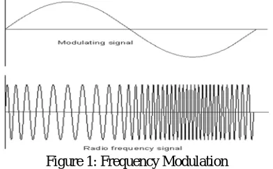
B. Frequency Modulation
[image:3.612.208.404.171.292.2]A type of modulation where the frequency of the carrier signal is modulated (changed) in proportion to the message signal while the amplitude and phase are kept constant.
Figure 1: Frequency Modulation
C. Phase Modulation
A type of modulation where the phase of the carrier signal is varied accordance to the low frequency of the message signal is known as phase modulation.
III. DESIGN OF FM TRANSMITTER
An FM transmitter is a portable device, which converts a specific audio output into an FM radio signal. It can be plugged into a CD player, satellite radio system, headphone jack, or a portable media player. One common use of an FM transmitter is to play music from an MP3 player through the speakers of a car. The majority of FM transmitters have a range of about 30 feet (about 9 meters). A good radio can increase that range to upwards of 75 feet (about 23 meters). Due to its low output, sometimes FM transmitters are not suitable for use in large urban areas, as the frequencies they use may become interrupted with other radio signals. This situation can be aggravated by strong FM signals that bleed into surrounding frequencies which the transmitter uses. The FM Transmitter uses FM waves (frequency modulated waves) to send sound. Frequency modulation transmits data (in our case an audio signal) over a carrier wave by changing the frequency of the carrier wave, where the frequency of the carrier wave corresponds to the voltage level of the audio signal. In order to use electromagnetic transmission, the audio signal must first be converted into an electric signal. The conversion is accomplished by a transducer, in our case the microphone. After conversion, the audio signal is used to modulate a carrier signal.
Figure 1: An example of frequency modulation. The top diagram shows the modulating signal superimposed on the carrier wave. The bottom diagram shows the resulting frequency-modulated signal.
A. Circuit Diagram
[image:3.612.195.416.520.646.2]Technology (IJRASET)
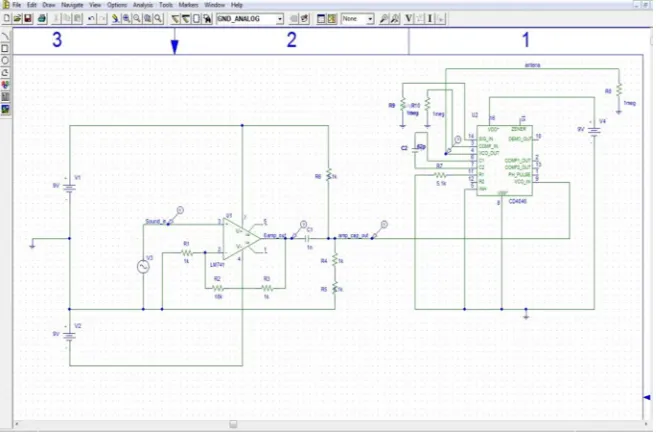
Figure2: P spice design for transmitter; the circuit on the left is the amplifier and the one on theright is the VCO circuit. 3.2 FM Transmitter and Receive Circuits Parts list
Description ID Value Total
Quantity
Unity Price Total Cost
Resistor R4, R6, R7 5.1k 3 2tk 6tk
Resistor R2 18k 1 2tk 2tk
Resistor R1,R3, R5 1k 3 2tk 6tk
Connector Female 3 5tk 15tk
Capacitor C2 62pF 1 10tk 10tk
Capacitor C1 470uF 1 20tk 20tk
Microcontroller CD4046 1 50tk 50tk
Op-Amp LM741 1 80tk 80tk
Battery V1, V2, V3 9V 3 50tk 150tk
Total= 17 339tk
IV. DESIGN OF FM TRANSMITTER
[image:4.612.143.471.454.672.2]A. P-Spice Circuit of FM Transmitter
Figure 3: P-spice design for transmitter; the circuit on the left is the amplifier and the one on the right is the VCO circuit. From the Figure we can see, Input audio signal is reproduced by V3 voltage source. Output signal from pin 4 of CD4046, is
R2 18k 1k V V 0 C2 62p R7 5.1k COMP_IN 3 INH 5 C1 6 C2 7 Z E N E R 1 5 SIG_IN 14 R1 11 R2 12 VCO_IN9 PH_PULSE1 COMP1_OUT2 COMP2_OUT13 VCO_OUT 4 DEMO_OUT10 V D D * 1 6 V S S * 8 U2 CD4046 V2 9Vdc + 3 -2 V + 7 V -4 OUT6 OS25 OS11 U1 LM741/NS V1 9Vdc R1 1k R3 1k R6 5.1k R4 5.1k C1 470u V4
FREQ = 1k VAMPL = 50mV VOFF = 0
0
V5
Technology (IJRASET)
transmitted by an antenna.
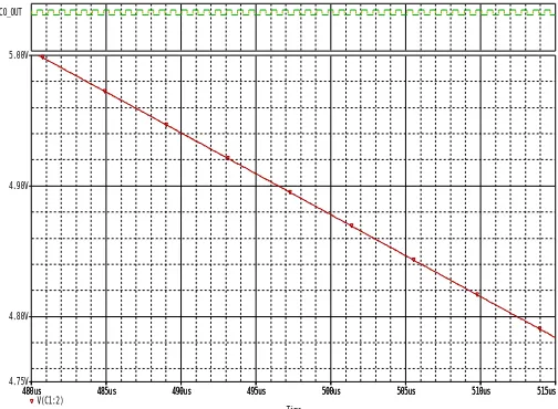
[image:5.612.128.475.110.257.2]B. Simulation of FM Transmitter
Figure 4: Simulation result of FM transmitter
[image:5.612.90.522.307.412.2]C. Simulation Results of Different Part Is Shown Individually
Figure 5: Input signal (green): from V3 voltage source Figure 6: Input signal (green): amplifier output before C1 capacitor
[Note Output signal (red): amplifier output before C1 capacitor ]
D. Simulation of FM Transmitter Amplifier Input and Output Input signal (red): zoomed in view of amplifier output/VCO input
Output signal (green): VCO output (digital signal with 9V amplitude) (shows center frequency of approximately 1.3MHz but our circuit will use the MC14046B, not the CD4046)
Figure 7: Transmitter amplifier input and output
Time
0s 0.1ms 0.2ms 0.3ms 0.4ms 0.5ms 0.6ms 0.7ms 0.8ms 0.9ms 1.0ms V(V4:+) V(R3:2)
-1.2V -0.8V -0.4V 0V 0.4V 0.8V 1.2V
Time
0s 0.1ms 0.2ms 0.3ms 0.4ms 0.5ms 0.6ms 0.7ms 0.8ms 0.9ms 1.0ms V(C1:2) V(R3:2)
-2.0V 0V 2.0V 4.0V 6.0V
Time
480us 485us 490us 495us 500us 505us 510us 515us
V(C1:2) 4.80V 4.90V
4.75V 5.00V
480us 485us 490us 495us 500us 505us 510us 515us
[image:5.612.181.433.514.699.2]Technology (IJRASET)
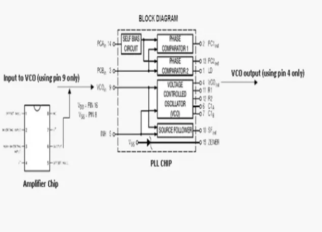
E. Transmitter Experimental Result
[image:6.612.148.464.125.353.2]For our transmitter side, we use the VCO circuit that is integrated into the CD4046 chip (phase locked loop chip).
Figure 8: Amplifier and VCO circuit (Source: LM741 and CD4046 datasheets)
[image:6.612.82.537.406.536.2]V. PROJECT BOARD& TOTAL PHOTO
Figure 9: Bread board design of the FM transmitter& Full photo of the project
Technology (IJRASET)
[image:7.612.74.546.222.469.2]Figure 11: Output of amplifier for transmitter with Input Audio Signal 150Hz& Output of transmitter’s VCO with Audio Signal 100Hz
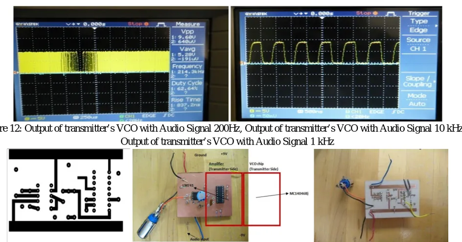
Figure 12: Output of transmitter’s VCO with Audio Signal 200Hz, Output of transmitter’s VCO with Audio Signal 10 kHz & Output of transmitter’s VCO with Audio Signal 1 kHz
Figure 13: FM Transmitter PCB layouts, FM Transmitter Circuit (top view) & FM Transmitter Circuit (back view)
VI. CONCLUSION & DISCUSSION
While doing the designation of FM transmitter circuit, we have faced a problem with the electronic component such the transistor and the variable capacitor referred with the serial number and the value to be used. In this part of problem wewere required to solve it and some alternative and creativity are needed to apply. While doing the construction process we found that several components are hard to do the soldering. It’s cause of the tracks circuit is design too thin at printed circuit board (PCB), and it makes the copper on the track draw out when soldering process done for many times. It is very important to hold attention due to produce the printed circuit board soon. We have to care about the value of the components related where the values of the components will affect the output of the FM transmitter circuit. After do the adjustment of the component’s value we have to do the simulation where the simulation result is performed by waveforms. We have been analyzing the waveforms and do comparisons with the theory due to checked and identified for any error when occurred. During completing this project, we had experienced several problems related for any scope of project. If anybody will run into any problem, the alternatives have been taken due to resolve the problem related to their research. We have to care for any alternatives taken to makes an excellent feedback for this research.
REFERENCES
[1] B.P. Lathi. Modern Digital and Analog Communication Systems, 3rd Ed. Oxford UniversityPress,1998. [2] “Communication Systems” 4th Ed.Simon Haykin.2001.
[3] S. Haykin. Communication Systems,3rdEdition.Wiley,1994.
Technology (IJRASET)
24(5): 689-740 .
[5] Leon W. Couch II, Digital and Analog Communication Systems, 8th edition, Pearson /Prentice,Chapter4.
[6] B. Boashash. editor. “Time-Frequency Signal Analysis and Processing—A ComprehensiveReference”. Elsevier Science. Oxford.2003. [7] Contemporary Communication Systems, First Edition by M F Mesiya- Chapter 5.
[8] DomenicoPorcino, Walter Hirt, "Ultra-wideband radio technology: potential and challenges ahead," Communications Magazine, IEEE, vol.41, no.7, pp. 66-74, July 2003.
[9] John F.M.Gerrits, MichielH. L. Kouwenhoven, Paul R. van der Meer, John R. Farserotu, John R. Long, “Principles and Limitations of Ultra-Wideband FM Communications Systems”, EURASIP Journal on Applied Signal Processing 2005:3, Hindawi Publishing Corporation, 382–396, 2005.
[10] JohnF.M.Gerrits, John R.Farserotu, John R.Long , "Low-Complexity Ultra-Wide-Band Communications," Circuits and Systems II: Express Briefs, IEEE Transactions on, vol.55, no.4, pp.329 333, April 2008.
[11] JoãoNascimento, “A Study on Range -Data Rate Performance of UWB Wireless Communications”, Institute Superior Técnico, 2007.
[12] ernandes, D. Wentzloff, “Recent Advances in IR-UWB Transceivers: An Overview”, IEEE Int.Symp. Circuits and Systems (ISCAS’10), pp. 3284-3287, May 2010.
BIOGRAPHY OF AUTHOR
Mr. Md Tanjil Sarker is the corresponding author of this paper. He successfully completed Bachelor Degree from Bangladesh University in the department of EEE and Studying post graduate degree in the Department of CSE, Jagannath University Dhaka Bangladesh. He conducted many research works in the relevant field such as Design, Inspection and Implementation of Solar PV Driven Smart& Automated Irrigation Systems, Electricity Load Calculative Method of an Inaccessible area of Bangladesh Etc. Now he is working as an Engineer in Bangladesh Research and education network (BdREN) Project in Bangladesh.
Md. Timur Rahman born in 1989 in Bangladesh. He accomplished his Bachelor degree in the area of Electrical & Electronic Engineering from Bangladesh University. He conducted many research works in the relevant field. Now he is working as an Engineer in a renowned group of Company in Bangladesh named Computer Source Ltd.
Prof. Dr. Md. Saiful Islam
Director- Institute of Information & Communication Technology, BUET, Dhaka, Bangladesh. He cordially supervised this research work as a supervisor. To know details about his research please visit http://iict.buet.ac.bd/?page_id=100
Md Nesaruddin had completed Diploma in Electronics Engineering from Barguna Polytechnic Institute, Bangladesh. Now he is working as an Engineer in a renowned group ofCompany in Bangladesh.
Mustakim Al MuntasirurRahman had completed B.Sc in Electrical & Electronic Engineering from Bangladesh University, Dhaka. Now he is working as an Engineer for Medical Machineries in a renowned pharmaceutical Company in Bangladesh.
Md Kamruzzaman had completed B.Sc in Electrical & Electronic Engineering from Bangladesh University, Dhaka. Now he is working as an Engineer in a renowned group of Company in Bangladesh.