www.ijiset.com
Influence of Multilayers On The Stress
Intensity Factors Of A Buried Elliptical
Crack.
Aly Rachid KorbeogoP
1
P
, Bernard K. BonziP
2
P
, Richard N. KouitatP
3
P
, Zacharie KoalagaP
1
P
, François ZougmoréP
1
P
1
P
Joseph Ki-Zerbo University, Doctoral School of Science and Technology (EDST, Materials and Environment Laboratory (LAME), Burkina Faso, [email protected],
[email protected], [email protected],
P
2
P
Joseph Ki-Zerbo University, Doctoral School of Science and Technology (EDST), Mathematics and Computer Science Laboratory (LAMI), Burkina Faso, [email protected],
P
3
P
University of Lorraine, Jean Lamour Institute, Dpt N2EV, UMR 7198 CNRS, Parc de Saurupt CS 14234, 54042 Nancy Cedex France, [email protected]
Abstract
The study of cracking mechanisms in multilayer structures has caught our attention in this work. In order to do this, we first went through a numerical validation of the method used, which is the boundary elements.
The method used allowed us to improve the computation time and reduce the numerical study of a dimension, it should be noted that this work also allowed to show the effectiveness of the method to treat the problems of partially open cracks. The results presented on the study of the multilayers were obtained following the study of a four-point bending on the one hand and a localized load on the upper face of the domain on the other hand applied on the multilayer in which one took care of buried an elliptical crack. The analysis of the results was done through the stress intensity factors. These simulations allowed us to highlight the influence of the position of the crack in the field of study
Keywords: Boundary elements method, sub domains, crack front25T.
1.
Introduction
The study of multilayers today is an important thing with regard to the increasingly important use of composite materials in mechanical engineering (Franck FC, Lawn RB, Mouginot R, Maugis D [1], [2], [3]). To do so, we are interested in numerical methods that make it possible to analyze the behavior of these multilayers through simulations. This has already been the subject of several researches. We can mention among others the methods of the finite elements and finite elements extended the methods without mesh etc. in this paper it will be necessary to predict the behavior of stress intensity factors along the crack front of a pre-existing crack trapped in a multilayer.
2. Problem definition
2.1. Statement of the problem
Consider a solid occupying a domain Ω of the frontier spaceΓ𝑛. We use the Cartesian coordinate system 𝑂𝑥𝑖 with i = 1, 2, 3. We note Γc the surface of the crack. Volume forces are neglected, and Einstein's index notation and summation convention are adopted. The balance of forces and moments in the absence of volume forces is written in the given coordinate system:
𝜎𝑖𝑗,𝑗= 0 𝑑𝑎𝑛𝑠 𝛺\Γ𝑛∪ Γ𝑐 (1)
With σ the Cauchy stress tensor, which in the case of linear elasticity in small deformations is related to the linearization tensor linearized by Hooke's law:
𝜎𝑖𝑗=𝐶𝑖𝑗𝑘𝑙𝜀𝑘𝑙 (2)
In relation (2), CRijklR is the fourth order isotropic tensor of the elastic constants of the material. It is expressed as a
function of the shear modulus (G) and the Poisson's ratio (ν) by:
𝐶𝑖𝑗𝑘𝑙=𝐺 �1−2𝜈2𝜈 𝛿𝑖𝑗𝛿𝑘𝑙+𝛿𝑖𝑘𝛿𝑗𝑙+𝛿𝑖𝑙𝛿𝑗𝑘� (3)
δRijR is the Kronecker symbol such that:𝛿𝑖𝑗=�
1 𝑠𝑖 𝑖=𝑗
0 otherwise
The tensor of the small deformations 𝜀𝑘𝑙is defined starting from the vector displacement u by:
𝜀𝑘𝑙=12�𝑢𝑘,𝑙+𝑢𝑙,𝑘� (4)
Let's assemble equations (2) and (4) and equation (1) can be rewritten as:
𝐶𝑖𝑗𝑘𝑙𝑢𝑘,𝑗𝑙= 0
The flow-type boundary conditions associated with this equation are of the form: The flow-type boundary conditions associated with this equation are of the form:
𝑡𝑖=𝜎𝑖𝑗𝑛𝑗 (5)
With 𝑛�⃗ the normal vector outside the considered boundary.
1.1 2.2 Method of solution
We use the so-called dual border element method [18]. The boundary of the domain is composed of the outer faces (ΓRnR)
and the crack 𝛤𝑐 which is itself made up of two faces 𝛤𝑐+and 𝛤𝑐− so that𝛤𝑐 =𝛤𝑐+⋃ 𝛤𝑐−. We introduce the displacement jump 𝛥𝑢𝑗(𝑥) =𝛥𝑢𝑗(𝑥+)− 𝛥𝑢𝑗(𝑥−) and the constrained vector jump𝛥𝑡𝑗(𝑥) =𝛥𝑡𝑗(𝑥+) +𝛥𝑡𝑗(𝑥−) ; xP
+
P
(or. xP
-P
) being a point, of the face 𝛤𝑐+ (or.𝛤𝑐−), of geometric coordinate x. We limit ourselves to cases of symmetrically charged cracks. In this case, the discontinuity relation of the constrained vector disappears from the equations.
For any point belonging to the outer boundary of the environment, we adopt the classical integral formulation in displacement, namely: � 𝑇𝑘𝑖(𝑥,𝑦)[𝑢𝑖(𝑦)− 𝑢𝑖(𝑥)]𝑑𝑆(𝑦) 𝛤𝑛 +� 𝑇𝑘𝑖(𝑥,𝑦)𝛥𝑢𝑖(𝑦)𝑑𝑆(𝑦) 𝛤𝑐+ =� 𝑈𝑘𝑖(𝑥,𝑦)𝑡𝑖(𝑦)𝑑𝑆(𝑦)
𝛤𝑛 (6)
𝑡𝑘(𝑥) =∫ 𝑇�𝑘𝑖𝛤𝑛 (𝑥,𝑦)𝑢𝑖(𝑦)𝑑𝑆(𝑦) +
∫ 𝑇�𝑘𝑖𝛤𝑐+ (𝑥,𝑦)𝛥𝑢𝑖(𝑦)𝑑𝑆(𝑦) − ∫ 𝑈�𝑘𝑖𝛤𝑛 (𝑥,𝑦)𝑡𝑖(𝑦)𝑑𝑆(𝑦)
www.ijiset.com
For the points located on the upper face of the crack, we adopt the constraint vector formulation:
In this formulation, the unknowns of the problem are the displacement and constraint vectors on the outer boundary, and displacement jump and stress on the faces of the crack.
The expressions of the influence functions that appear in equations (7) and (8) can be found in many works (e.g. [19, 20]). As already mentioned, the unknowns on the crack surfaces are the displacement jump vector (∆𝑢�⃗) and the stress vector 𝑡⃗(𝑥+).
The outer boundary and the face of the upper crack are subdivided into a finite number of elements. Nine compliant and / or semi-discontinuous elements are used for the elements of Γn. The elements of the surface of the crack are discontinuous. For the elements of the crack front, the interpolation introduced in Kouitat et al. [21] was adopted. The discretized form of the boundary equations (eq. (7) and (8)) then leads to systems of equations of the following form:
[𝐴𝑛]{𝑥𝑛} = {𝐹𝑛}−[𝐵𝑛]{∆𝑢}
{𝑇𝑐} + [𝐴𝑐]{∆𝑢} = [𝐺̅]{𝑡𝑛}−[𝐻�]{𝑢𝑛} (8)
Where {𝑥𝑛} is the vector of unknown nodal quantities on the outer boundary (displacements and constrained vectors); {∆𝑢} is the vector of jumps of nodal displacements; {u ^ n} is the vector of nodal displacements on the outer boundary; {𝑡𝑛} is the vector of nodal stress vectors on the outer boundary; {𝑇𝑐} is the vector of the nodal stress vectors on the
surface of the crack.
For the envisaged loading, the considered crack can be subjected to a mode of complex solicitation. On the face of the crack, the jumps of displacements and the constrained vectors are not known in advance. The crack may be completely closed, partially closed or completely open. Consequently, it is necessary to impose a unilateral contact condition on the faces of the crack. At a point x of the surface of the crack, we introduce the local coordinate system(𝑛�⃗(𝑥),𝜏⃗(𝑥),𝜌⃗(𝑥)). The vector 𝑛�⃗(𝑥) designates the normal external to the surface of the crack at the point x such that 𝜏⃗(𝑥) and 𝜌⃗(𝑥) are two mutually orthogonal vectors, and tangent to the plane of the crack. Normal displacement discontinuity and normal stress must satisfy:
∆𝑢𝑗𝑛𝑗=−∆𝑈𝑛≤0, 𝑡𝑗𝑛𝑗=−𝑡𝑛≤0 𝑒𝑡 𝑡𝑛∆𝑢𝑛= 0 (9)
If the crack opens, then∆𝑈𝑛≠0 and𝑡𝑛= 0 ; otherwise ∆𝑈𝑛= 0 and𝑡𝑛≠0.
We assume that the contact on the faces of the crack is frictionless. This indicates that the tangential components (𝑡𝜏 𝑒𝑡 𝑡𝜌) of the constrained vector are identically zero.
We have chosen to solve equations (8) and (9), combined with the one-sided contact condition, by an iterative scheme whose algorithm is summarized below:
This algorithm can be seen as a different presentation of the superposition method to solve the crack problems presented by Ameen and Raghuprasad [22] and applied to 2D compression fracture problems by Elvin and Leung [23] and by De Bremaecker and al. [24]. In a previous work, compression cracking is formulated as a complementarity problem and solved by the "PATH solver" algorithm. The algorithm has been used successfully by Christensen et al in [25].
The matrix equation system solved in step 1 remains unchanged during the iterative process. The matrix of the system is then factorized once and for all and stored, which allows a computation time saving. In step 2, the system of equations must be completed by the contact equations. For each node of the crack boundary, we write:
�𝑚𝑖𝑛(∆𝑢𝑛𝑡𝜏= 0,𝑡𝑛) = 0
𝑡𝜌= 0 (10) The system obtained is therefore nonlinear and not differentiable in the classical sense. We applied Newton's method using Bouligand's differentiability (B-differentiability) presented in Christensen et al. [22] and Martin Schwartz [26]. We emphasize that the need for a directional derivative is due to the min function in equation (10).
The results presented in the following were obtained using this algorithm. In all the cases tested, the average number of iterations to converge with ε = 10-12 is about 15.
3. Results
We specify that all the results presented in this part were obtained in a numerical experiment where we consider the isotropic domain.
3.1 Validation of the method
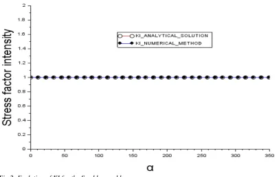
To validate our method of calculation we have taken over the digital experience which deals with the problem solved by Sneddon. For the particular case of a circular crack fleeing into an infinite mass subjected to uniform traction on the two lower and upper faces has been treated by Sneddon and the expression of the analytical solution of such a problem is given as follows(Ian Naismith Sneddon 1946; Ian N. Sneddon 1969; Sneddon I.N., s. d.) :
𝐾𝐼= 2𝜎�𝜋𝑟 (11)
�𝑟𝑎𝑑𝑖𝑢𝑠𝑠𝑡𝑟𝑒𝑠𝑠𝑜𝑓𝑡ℎ𝑒: 𝑐𝑟𝑎𝑐𝑘𝜎 : 𝑟
We consider the field of study represented in the following figure which is a parallelepiped. The material parameters used are a Poisson's ratio of ν = 0.3 and a Young's modulus E = 69Gpa. The domain is discretized by elements with nine nodes and consists of 96 elements distributed in 486 border nodes. The crack is circular and horizontal placed in the center in the area (see figure) it is discretized by 16 elements distributed in 288 nodes. The size of the crack and the domain depends on the parameters r and h specified below. The constant and uniform charge density applied is σ = 1.d-2Gpa. The side faces of the domain are free of stress the center of the domain is constrained to axial displacement the upper and lower faces are subjected to uniform traction.
www.ijiset.com
Fig. 1: Geometric representation of the domain and the crack
Fig.2: Evolution of KI for the Sneddon problem
3.2 Case of flexion
The material parameters are a Young's modulus of
E = 69Gpa and a Poisson's ratio of ν = 0.3. All the results presented were obtained in isotropy. For reasons of symmetry we will represent a portion of the crack front in the results of our simulations. The examples presented below are obtained with a uniform charge density applied as a bias. The analysis of the results is with the stress intensity factors (KI, KII and KIII) dimensioned by:
𝐾0=𝜎√2𝜋𝑟
The three factors called stress intensity factors determine the displacement of the crack lips by making a combination of three main modes denoted I, II and III.
Fig.3: Failure modes of a crack
The solar modules when they are fixed on a support during its operation undergo compression at its ends. In this part, the idea is to reproduce this mechanical action and to analyze its impact on our field of study.
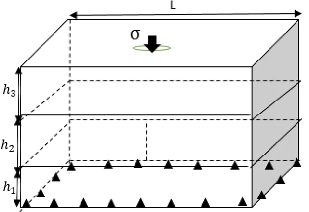
The multilayer consists of three layers, each layer is discretized with 216 elements divided into 1014 border nodes completed by 847 internal nodes. The elliptic crack is placed in the plane (XOZ) centered in the domain following the studied layer and is discretized with 32 elements distributed in 288 nodes. The study marker is a Cartesian coordinate system centered in the field. The lateral faces are free of movement the lower face is in plane support as shown in the following figure. The upper is loaded with a uniform charge density σ at both ends along the axis (OY).
Fig.4:Geometry of domains: elliptic crack, multilayer
Mode I :
opening
Mode II :
Sliding plane
Mode III :
www.ijiset.com
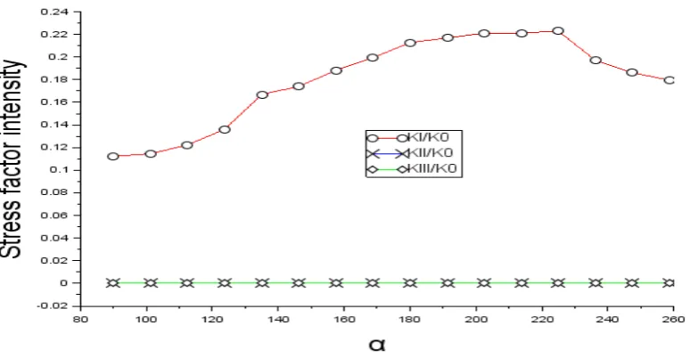
Fig. 5: Layer1 / evolution of stress intensity factors
The previous figure above shows the behavior of the stress intensity factors when the crack is in the bottom layer, the result allows to say that this position of the crack is the most dangerous configuration because the crack opens totally because the KI factor is not zero. The other two modes are null (KII and KIII)
Fig. 6: Layer2 / evolution of stress intensity factors
Fig. 7: Layer3 / evolution of stress intensity factors
For this type of loading the crack is in a dangerous configuration when it moves away from the loading face. The results show that the method makes it possible to treat the cases of partially open crack and to study the multilayer structures.
1.1 3.3 Load at a localized point
In this part, we study a particular case of mechanical action that a multilayer system exposed to the actions of nature may encounter. Indeed a projectile can target our system stored in nature. The multilayer consists of three layers, each layer is discretized with 216 elements divided into 1014 border nodes completed by 847 internal nodes. The elliptic crack is placed in the plane (XOZ) centered in the domain following the studied layer and is discretized with 32 elements distributed in 288 nodes. The study marker is a Cartesian coordinate system centered in the field. The lateral faces are free of movement the lower face is in plane support as shown in the following figure. The upper is loaded at the center point of coordinates (0 0 Z).
www.ijiset.com
Fig. 9: Layer1 / evolution of stress intensity factors
Fig.10: Layer3 / evolution of stress intensity factors
The dangerous configuration always remains the furthest position from the loading face. The shape of the curves is identical to the previous case, except for the changing amplitudes. Indeed the impact of a projectile on a building such as solar modules would be less dangerous than the pressure exerted on its surface during installation or maintenance.
4. Conclusion
References
[1]. Franck FC, Lawn RB. On the theory of Hertzian fracture. Proc Roy Soc A 1967; 299:291.
[2]. Mouginot R, Maugis D. Fracture indentation beneath flat and spherical punches. J Mater Sci 1985; 20:4354. [3]. Mouginot R. Crack formation beneath sliding spherical punches. J Mater Sci 1987; 22:989.
[4]. Bush MB. Simulation of contact-induced fracture. Engng Anal Bound Elem 1999; 23:59. [5]. Komvopoulos K. Subsurface crack mechanisms under indentation loading. Wear 1996; 199:9.
[6]. Choi HJ. Effects of graded layering on the tip behavior of vertical crack in a substrate under frictional Hertzian contact. Engng Fract Mech 2001; 68:1033.
[7]. Cruse TA, Vanburen W. Three dimensional stress analysis of a fracture specimen with an edge crack. Int J Fract 1971; 71(1):1. [8]. Mi Y, Aliabadi MH. Dual boundary element method for three-dimensional fracture mechanics analysis. Engng Anal Bound Elem 1992; 10:161.
[9]. Dominguez J, Ariza MP, Gallego R. Flux and traction boundary elements without hypersingular or strongly singular integrals. Int J Numer Meth Engng 2000; 48:111.
[10]. Young A. A single-domain boundary element method for 3-D elastostatic crack analysis using continuous elements. Int J Numer Meth Engng 1996; 39:1265.
[11]. Bonnet M. Stability of crack fronts under Griffith criterion: a computational approach using integral equations and domain derivatives of potential energy. Comp Meth Appl Mech Engng 1999; 173:337.
[12]. Aliabadi MH. A new generation of boundary methods in fracture mechanics. Int J Fract 1997; 86:91.
[13]. Man KW, Aliabadi MH, Rooke DP. Analysis of contact friction using the boundary element method. In: Aliabadi MH, Brebbia CA, editors. Computational methods in contact mechanics. Elsevier; 1993. R. Kouitat Njiwa, J. von Stebut / Engineering Fracture Mechanics 71 (2004) 2607–2620 2619
[14]. Dandekar BW, Conant RJ. Numerical analysis of contact problems using boundary integral equation method. Part I and II. Int J Numer Meth Engng 1992; 33:1513.
[15]. Takahashi S, Brebbia CA. Elastic contact analysis with friction using the boundary elements flexibility approach. In: Aliabadi MH, Brebbia CA, editors. Computational methods in contact mechanics. Elsevier; 1993.
[16]. Olukoko OA, Becker AA. A new boundary element approach for contact problems with friction. Int J Number Meth Engng 1993; 36:2625.
[17]. Karami G. Boundary element analysis of two-dimensional elastoplastic contact problems. Int J Numer Meth Engng 1993; 36:221.
[18]. A. P. Cisilino, M. H. Aliabadi, Three-Dimensional Boundary Element Analysis of Fatigue Crack Growth in Linear and Nonlinear Fracture Problems, Engineering Fracture Mechanics, vol. 63, pp. 713–733, 1999.
[19]. C. A. Brebbia, J. Dominguez, Boundary Elements: An Introductory Course, Computational Mechanics Publications, Billerica 1992.
[20]. M. Bonnet, Boundary Integral Equation Methods for Solids and Fluids, John Wiley and Sons, New York, 1999.
[21]. R. Kouitat Njiwa, J. von Stebut, Three Dimensional Boundary Element Analysis of Internal Cracks under Sliding Contact Load with a Spherical Indenter, Engineering Fracture Mechanics, vol. 71, pp. 2607–2620, 2004.
[22]. M. Ameen, B. K. Raghuprasad, A Hybrid Technique of Modelling of Cracks Using Displacement Discontinuity and Direct Boundary Element Method, Int. J. Fract., vol. 67, pp. 343–355, 1994.
[23]. N. Elvin, C. Leung, A Fast Iterative Boundary Element Method for Solving Closed Crack Problems, Engng. Fract. Mech., vol. 63(5), pp. 631–648, 1999
[24]. J. C. De Bremaecker, M. C. Ferris, D. Ralph, Compressional Fractures
Considered as Contact Problems and Mixed Complementarity Problems, Engng. Fract. Mech., vol. 66, pp. 287–303, 2000.
[25]. P. W. Christensen, A. Klarbing, J. S. Pang, N. Strömberg, Formulation and comparison of algorithms for frictional contact problems, Int. J. Numer. Meth. Engng. Vol. 42(1), pp. 145–175, 1998.
[26]. Martin Schwartz. Contribution to the resolution of three-dimensional problems of fragile cracking. Towards the use of a non-local model of elastic behavior. Other. University of Lorraine, 2018. French. NNT: 2018LORR0031. Tel-01749198