Three Phase Grid Connected PV System for
Mitigation of Voltage and Current Harmonics
Compensation Using SRF Method
K.Srinu
1, P.Madhu Chandra
2, K.Srinivas
3PG Student, Dept. of EEE, Sankethika Vidya Parishad College of Engineering, Visakhapatnam, India1 Assistant Professor, Dept. of EEE, Sankethika Vidya Parishad College of Engineering, Visakhapatnam, India2
PG Student, Dept. of EEE,Gayatri vidya Parishad College of Engineering, Visakhapatnam, India3
ABSTRACT: Power quality is an all-encompassing concept for a multitude of individual types of power system disturbances. The presence of harmonics in power supply network poses a severe power quality problem that results in greater power losses in the distribution system, interference problems in communication systems and, sometimes, in operation failures of electronic equipment. This paper presents a three -phase active power filter for harmonic compensation which is consists of a series active power filter and a shunt active filter. The active filter connected in series to a source acts as a harmonic isolator between the sources and loads whereas the shunt active filter is connected in parallel with a load and suppresses the harmonic current produced by the load and. reduce the total harmonic distortion (THD). The voltage source inverter (VSI) is the core of an active power filter. The hysteresis current control is a method of controlling the VSI. Hysteresis control can be either of fixed band type or adaptive band type. In this paper, Synchronous Reference Frame (SRF) theory is implemented for the generation of reference current signals for the controller. Mat lab /Simulink and are used for simulation. From the simulation results it is confirmed that the filter topology is capable of compensating the load current and voltage harmonic distortion within the stipulated limits laid down by the IEEE 519 standard.
KEYWORDS: Shunt active power filter, series active power filter, pv system ,voltage harmonics, current harmonics, nonlinear load.
I.INTRODUCTION
Power-electronics circuits are widely used in industrial equipment, such as frequency changers, motor-drive systems (AC voltage controller, chopper), etc. Such equipment presents nonlinear impedance to the utility, generating large harmonic currents and voltages with well-known conflicting effects, such as low power factor, low efficiency and destruction of other equipment. Also, some precision instruments and communication equipment will be interfered with the EMI. The effects of current harmonic distortion are poor utilization of distribution wiring and plant, increased power loss, high current flow in the neutral line and dangerous cable overheating. Voltage harmonic interrupts the proper operation of digital electronics mainly communications and process control, which needs sinusoidal supply voltage. Harmonic problem may result in mal-operation of protection equipment. To minimize the power quality problems by solely active Filters, different from the passive filter, have the capability of dynamically adjusting to the conditions of the system in terms of harmonics and reactive power compensation.
features and it causes little environmental burden, it is of a modular type technology that can be easily expanded, and it is applicable almost everywhere. This paper presents an analysis and simulation of a PV interactive Active Power Filter topology that achieves simultaneously harmonic current damping and reactive power compensation. Also, the inverter is always used to act as an active power filter to compensate the nonlinear load harmonics and reactive power. In the day-time with intensive sunlight, the PV interactive active power filter system brings all its functions into operation. At night and during no sunlight periods, the power required by the load is received from the distribution system while the inverter system only provides reactive power compensation and filter harmonic currents and voltage The effectiveness of Active Power Filter depends on the requirements, inverter type and topology. On the basis of topology Active Power Filter can be classified as series connected Active Power Filter and Shunt connected Active Power Filter. Series connected Active Power Filter can be connect before the load in series with the mains using a matching transformer to eliminate the voltage harmonics and to balance and regulate the terminal voltage of the load. Also it can be used to regulate the negative sequence voltage at the load. So the series Active Power Filter works as a controllable voltage source. The drawbacks of this series connected Active Power Filter is, it only compensates the voltage harmonics and another problem is for the short circuit in the load end. This short circuit current passes through the series transformer winding, which may overload the series transformer. A shunt active power filter (SAPF) is a device that is connected in parallel to a group of loads. it cancels the reactive and harmonic currents drawn by the load so as to make the supply current sinusoidal.
II. SYSTEM CONFIGURATION
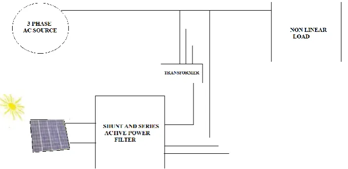
The proposed topology consists of a series and shunt active power filter and pv system. The active filter connected in series to a source acts as a harmonic isolator between the source and load whereas the shunt active filter is connected in parallel with a load and suppresses the harmonic currents produced by the load as shown in Figure 1.
Fig .1 proposed topology consists of series and shunt active power filter and pv system
The series active filter compensates the harmonic voltage by synchronous reference frame (SRF) -based controllers. The shunt active filter compensates the harmonic currents by using synchronous reference frame (SRF) -based controllers. The three-Phase PLL used for generation of the unit vector coordinates (sin θ and cos θ) used in the SRF-based algorithms. The SRF-SRF-based controller was used to generate the sinusoidal compensating current and voltage references applied to a three-phase line-interactive pv System
.
III.PV MODEL
with energy greater than the band-gap energy of the semiconductor creates some electron-hole pairs proportional to the incident irradiation. To find the model of the photovoltaic generator, we must start by identifying the electrical equivalent circuit to that source. Many mathematical models have been developed to represent their highly nonlinear characteristics resulting from that of semiconductor junctions that are the major constituents of PV modules. There are several models of photovoltaic generators which have a certain number of parameters involved in the calculation of voltage and current output. In this study, we will present the model of single diodes (Fig.2) taking into account the internal shunt and series resistances of the PV cell.
Fig.2 Model of a photovoltaic cell
The current source Iph represents the cell photocurrent. Rsh and Rs are the intrinsic shunt and series resistances of the
cell, respectively. Usually the value of Rsh is very large and that of Rs is very small, hence they may be neglected to
simplify the analysis.PV cells are grouped in larger units called PV modules which are further interconnected in a parallel-seriesconfiguration to form PV arrays.
The photovoltaic panel can be modelled mathematically as given in equations (1)- (4)
Module photo-current:
I
ph=[ I
SCr+K
i(T-298)]*
Module reverse saturation current :
I
rs= I
SCr/
[exp(Qv
OC/
N
SkAT) – 1] (2)
The module saturation current I0 varies with the cell temperature, which is given by
I
O= I
rs[
𝑇/𝑇
r]
3exp [
𝑞∗𝐸𝑔𝑜𝐵𝑘 1 𝑇𝑟
−
1
𝑇
] (3)
The current output of PV module is
I
PV= N
P*I
Ph-N
P*I
0[exp
𝑞∗(𝑉𝑃𝑉 +IPV 𝑅𝑠)
𝑁𝑆 𝐴𝑘𝑇
− 1]
(4)
Where Vpv and Ipv represent the output voltage and current of the PV, Iph is the photocurrent; IO are diode saturation
(1.381e-23 J/K); T is cell temperature (K); NS are P-N junction ideality factor; Rsh and Rs are the intrinsic shunt and
series resistance of the cell respectively; Ns is the number of cells connected in series is 36 ;Np is the number of cells
connected in parallel is 1.
IV. CURRENT AND VOLTAGE HARMONIC DETECTION
In this paper synchronous reference frame (SRF) method is used to generate the reference voltage and current required to compensate the voltage and current harmonics. The three voltage and/or current signals in a-b-c coordinates are transformed to the orthogonal α-β stationary frame using (1) and then to synchronous rotating frame (d-q) using (2). Based on the control needs the required components are extracted/ separated in d-q frame. To generate the reference signals and thus, to transform them back to original frame, the inverse transformation from d-q to α-β frame, and then to a-b-c frames carried out utilizing (3) and (4), respectively
i. Clark’s Transformation
It transforms sensed source voltage /current signal from a-b-c stationary to α-β stationary coordinate system by following equation (5)
52 1 2 3 2 1 2 1 2 3 2 1 2 1 0 1 3 2 o cc cb ca x x x x x x
ii. Park’s Transformation
Now this signal α-β is converted in d-q frame by using equation (6)
6
cos
sin
sin
cos
q dx
x
t
t
t
t
x
x
iii. Reverse Park’s Transformation (α-β to d-q)
7
cos
sin
sin
cos
x
x
t
t
t
t
x
x
q div. Reverse Clark’s Transformation (d-q to a-b-c)
8 .. 2 1 2 1 2 1 2 3 2 3 0 2 1 2 1 1 3 2 c b a x x x x x x A. Current SRF controller
In this method the measured load currents are transformed into the rotating reference frame (d-q frame) that is synchronously rotating at the line current frequency using (5) and (6).The line frequency components of the load currents become DC quantities and the harmonic components are frequency shifted by ωt in the d-q reference frame. A high pass filter in the d-q frame, with a cut-off at the line frequency can be used to extract the DC components.
Currents to transform them back to original frame, the inverse transformation from d-q to α-β frame, and then to a-b-c
frame is carried out utilizing (7) and (8).Reference compensating currents(ica*,icb*,icc*) generated using current SRF
controller which shown in fig 3
B. Voltage SRF controller
In this method the measured voltages are transformed into the rotating reference frame (d-q frame) that is synchronously rotating at the line voltage frequency using (5) and (6).The line frequency components of the voltages become DC quantities and the harmonic components are frequency shifted by ωt in the d-q reference frame. A high
pass filter in the d-q frame, with a cut off at the line frequency can be used to extract the DC components. Voltages to
transform them back to original frame, the inverse transformation from d-q to α-β frame, and then to a-b-c frame is carried out utilizing (7) and (8).Reference compensating voltages(vca*,vcb*,vcc*) generated using voltage SRF controller
which shown in fig3
Fig.3 current SRF controller and voltage SRF controller
V. HYSTERESIS CONTROLLER
Fig.4 Hysteresis Band and Generation of Pulses
VI. SIMULATION RESULTS
The proposed model for a shunt series active power filter using harmonic detection method with hysteresis current controller has been successfully modelled and tested using MATLAB/SIMULINK toolbox.
Fig.5 Distorted current at source without compensation
Fig .5 shows current wave form at the source .where shunt and series active power filter is absent in the system .
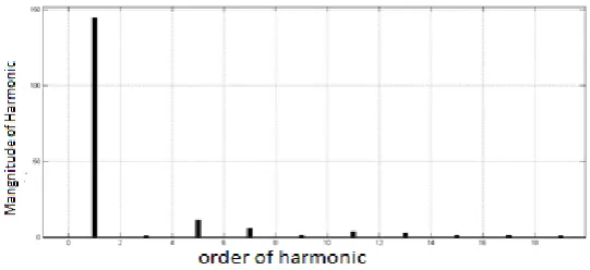
Figure 7.Shows FFT analysis for figure 5 wave from. Harmonic currents are injected into power system by nonlinear load. Because of harmonics source current will be distorted. For distorted current THD is 22.06%.
Fig. 7 Distorted voltages at source without compensation
Fig .7 shows voltage wave form at the source .where shunt and series active power filter is absent in the system .
Fig. 8 FFT analysis for above distorted voltages wave form
Figure 8 shows FFT analysis for figure 7 wave from. Harmonic voltages are injected into power system by Nonlinear load. Because of harmonics source voltages will be distorted. For distorted current THD is 11.03%.
Fig .9 shows current wave form at the source .where shunt and series active power filter is present in the system .
Figure 10. FFT analysis for above currents wave form
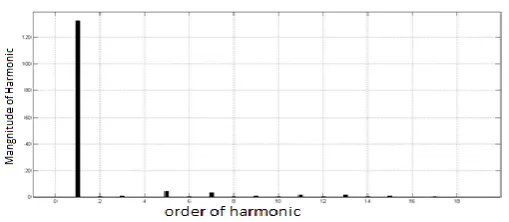
Figure 10 shows FFT analysis for figure 9 wave from .Compensating currents are injected into power system by SAPF. AS a result THD is reduced 22.06% to 2.03%, reactive power will decreased and power factor will improve.
Fig. 11 voltages at source after compensation
Fig .11 shows voltage wave form at the source .where shunt and series active power filter is present in the system .
Fig. 12 FFT analysis for above voltages wave form
V. CONCLUSION
This paper presents some insight about the pv system interactive active power flow in an electrical system with a three Phase Series and shunt Active power filter. The presented three -Phase Series and shunt Active power filter makes use of two back-to-back converters with different purposes and distinct coupling with the electrical power system. One is shunt connected to the electrical grid through a transformer, and the other is series connected without a transformer to the electrical grid. The Shunt Converter performs the regulation of the DC link shared by both converters, by consuming or injecting sinusoidal current. The Series Converter compensates Power Quality issues related with the voltage waveform. The analysis of the active power flow through an electrical system is performed mathematically, and Simulation results were obtained to verify those active power flow issues in a harmonic free electrical System.
REFERENCES
[1].Hirofumiakagi,yoshihirakanazawa, and akira Nabae“Instantaneous Reactive Power Compensators Comprising Switching Devices Without Energy Storage Components”, IEEE transactions on industry applications,vol.Ia-20,no.3, may/june 1984.
[2].Vasundhara Mahajan, Pramod Agarwal, Hari Om Gupta “Simulation of Shunt Active Power Filter using Instantaneous Power Theory” IEEE Fifth Power India Conference on Dec.2011.
[3].Ned Mohan ,Undeland and Riobbins, “Power Electronics: Converters, Application and Design”, Wiley India edition,3rd Edition,September 2002.
[4]. Bhattacharjee, K. “Harmonic Mitigation by SRF Theory Based Active Power Filter using Adaptive Hysteresis Control” IEEE Power and Energy Systems Conference: Towards Sustainable Energy, March 2014.
[5]. Khadkikar, V.and Chandra, A.“Control of Single-phase UPQC in Synchronousd-q Reference Frame” IEEE Harmonics and Quality of Power (ICHQP), 2012 IEEE 15th International Conference on June 2012.