ISSN (Print) : 2320 – 3765 ISSN (Online): 2278 – 8875
I
nternational
J
ournal of
A
dvanced
R
esearch in
E
lectrical,
E
lectronics and
I
nstrumentation
E
ngineering
(An ISO 3297: 2007 Certified Organization) Website: www.ijareeie.com
Vol. 6, Issue 5, May 2017
Robust Controller for Hydro-Plants to
Mitigate Frequency Deviations with Wind
Power Penetration in the Grid
A.Yuva Kishore1, G.Ravindra2
PG Student, Department of EEE, SVEC, Tirupati, India1
M.Tech, Asst. Prof, Department of EEE, SVEC, Tirupati, India2
ABSTRACT: This paper exhibits a robust control configuration to incorporate hydro generators to address expanded frequency deviations in power frameworks with high wind control entrance. A Robust control plan system for hydro governors is proposed so as to especially handle with unsettling influences from wind control variance. In the first place, by consolidating state conditions of hydro, thermal, and wind generators through the power stream conditions of system, a state space model of the whole power framework is determined for the control plan of hydro generators. Specifically, the attributes of wind power varieties and the water powered framework flow of hydroelectric power
plants are executed in the framework demonstrate. At that point, the H∞-based vigorous controller is integrated by
diminishing the request of the framework model and utilizing the direct network disparity strategy. At long last, the IEEE 39-transport test framework is utilized to check the execution of the planned strong controller with 10–40% wind entrance levels. Reenactment results are contrasted and a conventional PID controller. Inquire about discoveries show that the proposed robust controller fundamentally lessens framework frequency deviations and empowers hydro generators to be more receptive to wind control variety in essential frequency direction of energy frameworks.
KEYWORDS: Frequency control, hydroelectric power generation, robust control, wind power.
I. INTRODUCTION
ISSN (Print) : 2320 – 3765 ISSN (Online): 2278 – 8875
I
nternational
J
ournal of
A
dvanced
R
esearch in
E
lectrical,
E
lectronics and
I
nstrumentation
E
ngineering
(An ISO 3297: 2007 Certified Organization) Website: www.ijareeie.com
Vol. 6, Issue 5, May 2017
control framework of hydro governors is designed based on parameters of thehydro generation system itself, ignoring the dynamics of other power system components [13]. These controllers therefore cannot adjust other disturbance sources in power systems, leading to larger system frequency deviations.
This limitation may restrict the frequency control performance of hydro generators inpower systems with high wind penetration. Furthermore, hydroelectric power plants have special behaviors heavy water columns are presented inside penstocks when water flow control valves operate during the regulation process [14]. Due to the higher wind power penetration, more frequent and rapid regulation actions will be required for hydroelectric power control.
Traditionally, the PID control law is widely implemented in a hydro governing system [15], but with more control challenges brought about by wind power fluctuation, new control methods need to be developed to improve the frequency control performance of hydro generators to mitigate high wind penetration challenges. For the property of
guaranteeing the robustness and stability in dynamic systems with bounded uncertainties and disturbances, the H∞
-based robust control method has been increasingly applied in regulating power system frequency recently [3], [4], [16]. Hence, considering wind power fluctuations a source of disturbance, implementing a robust control method on hydro generators will help damp system frequency deviations and improve the performance of hydro governing systems. In this paper, the primary frequency control problem introduced by wind power is studied by deriving a state space model of the entire power system including the characteristics of wind power variation as well as the dynamics of hydroelectric power plants. Based on this model, the challenge of wind power fluctuation causing frequency deviations
in power systems canbe addressed by applying the H∞-based robust control method on hydro generators.
This paper is organized as follows: In Section II, the frequency regulation problem is formulated and state
space models used for studying this problem are presented. Section III describes details of the proposed H∞-based
robust control method for primary frequency control. Simulations and analysis on the IEEE 39-bus test system are discussed in Section IV to illustrate the performance of the proposed controller. Finally, conclusions and future work are addressed in Section V.
II. THE GENERALIZED MODEL OF POWER SYSTEMS
This paper focuses on the primary frequency control problem due to the continuous wind power fluctuation in the timescale of seconds to a few minutes. In this section, a common state space representation of an interconnected power system including hydro generation, thermal generation, wind generation and power flows is derived. Later a robust controller is designed and added into the frequency control loop of hydro generators based on this state space model. As this work focuses on frequency control problems, an emphasis is placed on the real power and frequency aspects and the detail of voltage dynamic is omitted. Particularly, more details are considered in the modeling of hydropower plant and characteristics of wind power in order to geta more effective hydro controller to mitigate system frequency deviations caused by wind power fluctuation. In order to simplify the frequency control problem, loads are assumed to be constant as their variations are small enough compared to wind power variation in the considered timescale[3] and all models in this paper are linearized around the equilibrium point. Units of each model are in the per unit system with respect to their rated base values.
A. Hydro Generation Model
ISSN (Print) : 2320 – 3765 ISSN (Online): 2278 – 8875
I
nternational
J
ournal of
A
dvanced
R
esearch in
E
lectrical,
E
lectronics and
I
nstrumentation
E
ngineering
(An ISO 3297: 2007 Certified Organization) Website: www.ijareeie.com
Vol. 6, Issue 5, May 2017
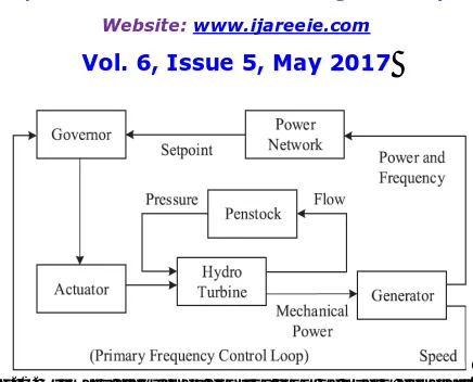
Fig. 1. Primary frequency control loop of hydro generation.
control loop are modeled based on an equivalent single turbine system as shown in Fig. 1.The discharge flow q and
mechanical power Phm of hydro turbine are usually represented by the functions of pressure h atthe inlet of turbine,
opening value Y of the water flow control valve and rotating speed ω, which is known as the hydro turbine
characteristic curve [20]. Linearized functions can be expressed in (1). Parameters a11 to a23are obtained by linearizing
turbine characteristic curve around the equilibrium point.
ΔQ = a11ΔH + a12 ΔY + a13 Δω
Δ = a21ΔH + a22 ΔY + a23 Δω --- (1) a , a , a , a , a , a = ( , , , )---(2)
As for the water passage system, an equivalent penstock is used for representation. The linearized model of penstock is
shown in (3), where Tw is the water time constant of the penstock
̇ = ΔH ---(3)
Equation (3) represents an important characteristic of a hydroelectric power plant which has been analyzed in detail by Kundur in [1]. He indicated that if back pressure is applied atthe end of the penstock by closing the control valve, the water inthe penstock will decelerate. However, the flow will not change immediately due to water inertia, causing the
power output of hydro turbine to increase. With a dynamic response determinedly Tw , the water flow decelerates until
it reaches a new steady value which establishes the new steady turbine power value. This means the initial turbine power will be opposite to the direction of the change in the valve gate position, which makes the hydro generation
system a non-minimum phase system [1,Ch. 9, p. 382].The dynamic of a servo actuator is shown in (4), where ∆ is
the control signal, ΔY is the gate position and parameter Tyis the time constant of the actuator
∆ +∆ =∆ ---(4)
To analyze the frequency control process, electrical dynamic of generators may be neglected and rotational dynamic of
turbine-generator can be captured by a single rotating mass with inertia Htdriven by accelerating torque ΔTkmand
decelerating torquesΔTkeas shown in (5). It is assumed that
2 ̇ = - ---(5)
Δ ≈ ΔThm,,Δ ≈ ΔTheas rotating speed is usually controlled tightly around ω0 . Parameter Shrepresents the ratio
ofpower base values between a hydro generator and the power network, and parameter egis the damping factor of the
hydro generator. By combining the hydraulic dynamics (1), (2) and (3) together with the actuator dynamic (4) and the rotor dynamic (5), the state space model of the entire hydro generation system is shown in
ISSN (Print) : 2320 – 3765 ISSN (Online): 2278 – 8875
I
nternational
J
ournal of
A
dvanced
R
esearch in
E
lectrical,
E
lectronics and
I
nstrumentation
E
ngineering
(An ISO 3297: 2007 Certified Organization) Website: www.ijareeie.com
Vol. 6, Issue 5, May 2017
B. Thermal Generation Model
The model of a thermal generation system is the same as that of the hydro generation system except for prime movers and speed governors. With the first order equation (7) representing steam turbine and a standard proportional droop control (8)representing speed governors [21], the fourth order state space model for thermal generation given by (9) is adopted
ΔP = ( )---(7)
Δu = ---(8)
g
g g g m ch ch g g g g g g m P S H P Y T T T R T H H P Y
k
* 0 0 2 1 0 * 1 1 0 0 0 1 1 0 0 2 1 2 0 0 0 0 0
---(9)where, ω0is the nominal rotating speed; Hg, Kg, Sgare the inertia constant, the damping factor and the ratio of power
base between the thermal generator and the power network, respectively;Tch, Tgare the time constant of a steam turbine
and anactuator, respectively; and R is the speed droop coefficient of a thermal speed governor.
C. Wind Generation Model
In this work, wind generators are modeled as negative loads injecting into the power grid, and wind power outputs are therefore not affected by other components of the interconnected power network. Meanwhile, this also implies that they make no contribution to system frequency regulation [22]. Hence, variation of wind power can be regarded as disturbances to the power system in the frequency control design stage. In order to capture the characteristics ofwind power variation, frequency spectrum is used for frequency domain representation of wind generation. As for this work, the Fast Fourier Transform method is applied on measured wind power data to obtain the power spectrum density (PSD) [23]. When wind speed data are available, wind power data can be calculated from wind speed data and turbine characteristics. Then, a rational transfer function (10), which is the ratio of two polynomials with real coefficients, is used to fit the PSD of wind power data. For simplicity, orders of the numerator and denominator polynomials are set to one and two, respectively
( ) = .
. ---(10)
Parameters a, b and c in (10) are selected using a trial-anderrormethod. When changing each parameter, some particular regularity appear in the shape of this function’s frequency response. Parameters, of which its transfer function (10) offers the best fit to the PSD of the measured data, are chosen. Then, the transfer function of wind power variation, which has a similar frequency response to the measured data, is obtained. This function is integrated into the frequency control design as discussed in Section III.
D. Power Flow Model
In order to simplify the power flow model, voltages at all buses are supposed to be controlled at nominal values as reactive power is perfectly compensated locally [4]. Real power balance is therefore the only constraint to be
considered. Hence, the DCpower flow model, expressed in (11) is applied to the power network model [24].Where, ΔP
represents the power variation at each bus; Δθrepresents power angle variation; and His the admittance matrix of the
power network
∆ = .∆ ---(11)
E. Entire Power System Model
For a specific interconnected power system, we can designate one or several hydro generators to mitigate the system frequency deviation caused by fluctuation in wind power output. From this perspective, control design of hydro governors should be based on the overall system model.
ISSN (Print) : 2320 – 3765 ISSN (Online): 2278 – 8875
I
nternational
J
ournal of
A
dvanced
R
esearch in
E
lectrical,
E
lectronics and
I
nstrumentation
E
ngineering
(An ISO 3297: 2007 Certified Organization) Website: www.ijareeie.com
Vol. 6, Issue 5, May 2017
̇= + ∆ + ∆
∆ ---(12)
As for wind generators, wind power outputs can be connected with electrical power of hydro and thermal generators
throughtheDCpower flow model. The corresponding admittance matrixcan be partitioned as shown in (13).ΔPleremains
zero as loads are assumed to be constant in this work
l w g h
l e w e
g e
h e
H
H
H
H
P
P
P
P
22 21
12 11
---(13)
ReplacingΔPhe;ΔPge_in (12) with ΔPweby substituting(13) into (12), the final state space expression of the entire
power system is obtained as shown in (14). This model is used for the subsequent H∞-based controller synthesis
̇ = + ∆ + ∆ ---(14)
III. ROBUST CONTROL FRAMEWORK
A. Proposed Control Strategy
In the traditional frequency control framework of a hydro governor, a fixed reference signal is compared with the local frequency feedback to decide the governor input, and the governor design is based on dynamics of the hydro generation system[13]. This implies that this kind of control do not consider the characteristics of system disturbances. In order to fundamentally address the frequency regulation problem introduced by wind power variation, an improved frequency feedback control framework for hydro generators is proposed by taking the wholepower system as the control object,
and wind power variation as the disturbance to the system. The designed controller K(s) adjusts the power output of
hydro turbine by adjusting the position of hydro valve based on frequency measurements. In this work, uncertainties of sensors and actuator are not considered and the control design is deployed based on the single turbine system derived in the previous section. Note that in addition to frequency, other system variables might be also considered for the feedback design, such as power and pressure outputs of the hydro turbine [25].
B. Robust Control Method
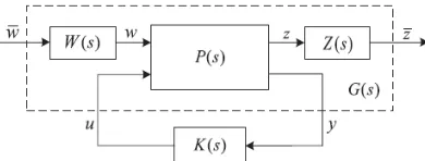
The standard H∞ control problem can be depicted by thestate space model expressed in (15), where x represent the
internal states vector of the system; y, z represent the measurement vector and the performance vector, respectively; w
is the exogenous inputs including disturbances, references and measurement noises; and u is the control input to be
designed [26]
Fig. 2.Augmented G plant for robust control synthesis.
Then, the H∞ control problem is established to seek for the optimal stabilizing controllerK(s) to minimize theH∞ norm
ofthe system closed-loop transfer function, which is represented byTwz(s) in this paper. This norm has several
interpretations which corresponds to the peak of the maximum singular value of the complex matrix Twz(jw) in the
frequency domain andthe largest input/output gain in the time domain [26] as shown in
̇= + + u
= + +
ISSN (Print) : 2320 – 3765 ISSN (Online): 2278 – 8875
I
nternational
J
ournal of
A
dvanced
R
esearch in
E
lectrical,
E
lectronics and
I
nstrumentation
E
ngineering
(An ISO 3297: 2007 Certified Organization) Website: www.ijareeie.com
Vol. 6, Issue 5, May 2017
‖ ‖∞= ( ( ) = ‖ ‖
‖ ‖---(16)
In this way, the H∞ control method can be derived as an optimization problem and can be solved by Riccati-based and
linear matrix inequality (LMI)-based approaches [26], [27].
C. Implementing Weighting Functions
The H∞ control method can also be applied to disturbance rejection problems as it guarantees the performance bound
of the control system subjected to any bounded disturbance. In order to characterize the disturbance and performance
signals, dynamic weighting functions are assigned to w and z as shown in Fig. 2. The standard control problem
therefore changes into the following weighted H∞ control problem (17).WhereW(s)andZ(s) are the weighting functions
of the disturbance and performance signals, respectively
. ( )‖ ( ) ( )‖∞---(17)
̇ = +
= + ---(18)
̇ = +
= + ---(19)
u D B B W B D B x x x A C B A C B A x x x Z W W z w Z Z W W z w 12 2 _ 1 1 1 0 0 0 0 0 0
D
D
D
w
D
D
u
x
x
x
C
C
D
D
C
D
Z
Z W zz w Z W Z
Z 1 11
11
12
D
D
w
D
u
x
x
x
C
D
C
y
W w 21 W 222 12
2
0
---(20)ISSN (Print) : 2320 – 3765 ISSN (Online): 2278 – 8875
I
nternational
J
ournal of
A
dvanced
R
esearch in
E
lectrical,
E
lectronics and
I
nstrumentation
E
ngineering
(An ISO 3297: 2007 Certified Organization) Website: www.ijareeie.com
Vol. 6, Issue 5, May 2017
With properly selected weighting functions W(s) and Z(s),which can be transferred to the state space form as shown in
(18)and (19), the augmented system model (20), which includes dynamic characteristics of exogenous input signals, is
obtained by integrating equations (15), (18) and (19). With this augmented model, the H∞ based robust controller
accounting for the characteristics of exogenous disturbances can be synthesized by solving the standard H∞ control
problem.
D. Model Order Reduction
According to [26], the resulting controller by solving the H∞control problem (16) is of dynamic type and has the same
order as the augmented plantG(s). For the frequency control problem, the augmented plant G(s) may have very high
order. Although, modern microprocessors make the implementation of high order controllers possible, these controllers may be complex and inefficient for practical implementation. A low order controller can be obtained by reducing the order of the augmented plant prior to the controller design, or reducing the controller order in the final stage, or both. In this work, the former approach is adopted using the standard Hankelnorm approximation method [26].
IV. MATLAB SIMULATION RESULTS
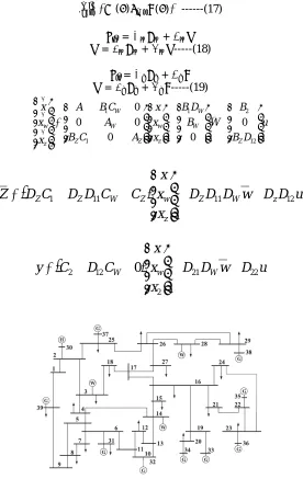
The control design approach proposed in the previous sections applied to the IEEE New England 39-bus test power system. The generator on Bus 30 is set to be a hydroelectric power plant with capacity of 500 MW, and wind generators are located atBus 3, Bus 14 and Bus 28 as shown in Fig. 3. Basic parameters ofthis test system are taken from [28] and detailed parameters of the hydroelectric power plant are listed in Table I. Capacities of the three wind generators at Buses 3, 14 and 28 are 1.5MW, 1.5 MW and 1.5MW, respectively. System loads have been increased in proportion to the average wind power outputs to make sure that generation andload of the system is balanced, and all loads are assumed to be constant for the considered time horizon of 5 seconds. Two cases are studied and compared in this work. The base case corresponds to the situation where the hydro generator is equipped with the PID controller,
whose parameters are shown an Table I. In the second case, the H∞-based robust controllers synthesized and
implemented on the hydro generator. In both cases, all other thermal generators are equipped with proportional droop control.
Penstock
Water time constant(Tw)
3.2
Turbine
a11 0.5 a12 1 a13 0.1
a22 1 a22 1.5 a23 0.1
Governer
Kp 5 Kd 0.5 Ki 0.1
ISSN (Print) : 2320 – 3765 ISSN (Online): 2278 – 8875
I
nternational
J
ournal of
A
dvanced
R
esearch in
E
lectrical,
E
lectronics and
I
nstrumentation
E
ngineering
(An ISO 3297: 2007 Certified Organization) Website: www.ijareeie.com
Vol. 6, Issue 5, May 2017
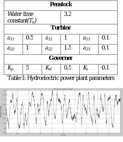
Fig. 4. Wind power variations in three wind farms.
the controller to tackle with wind power fluctuation. With this kind of control design, the robust controller is expected to provide better control performances than a typical PID controller in power system frequency regulation. Note that wind generators are modeled as negative loads in this work. As supplementary control may be applied on wind generators to make them dispatch able [30], it is still possible to apply similar robust controllers on hydro generators to damp the system frequency deviations by implementing new models of wind generators into modified system model, but the damping effects of the controller may be less significant when windgenerators are dispatch able.
C. Time Domain Simulation Results
In order to provide further illustrations on the performance ofthe synthesized controller, time domain simulations of both PIDcontrol and robust control with wind penetration are carried out. By solving the closed-loop transfer functions of the entire system with the PID controller and the designed robust controller in time domain, which is also accomplished with MATLAB, system frequency responses under specific wind power disturbances are obtained. Wind power profiles of three wind generators in the test system are shown in Fig. 4, which havea time horizon of 5 seconds. Variation of wind power is represented by deviation values around the mean value within this time horizon of 5 seconds, and the system is assumed to be in
Fig. 5.System frequency response to wind power variation
with a typical PIDcontrol and with the proposed robust control and the system I assumed to be in the equilibrium state at the beginning time of simulation. System frequency responses to these wind variations are shown inFig. 8. Here, the
ISSN (Print) : 2320 – 3765 ISSN (Online): 2278 – 8875
I
nternational
J
ournal of
A
dvanced
R
esearch in
E
lectrical,
E
lectronics and
I
nstrumentation
E
ngineering
(An ISO 3297: 2007 Certified Organization) Website: www.ijareeie.com
Vol. 6, Issue 5, May 2017
superior control result. Simulations are also carried out at different wind penetration levels in the test system, with capacities of other generators keep the same. As variance, which is a descriptor in statistics, can measure how far a set of numbers is spread out [31], it issued to represent the frequency deviation level. These frequency response simulation results prove that the designed robust controller has effectively reduced system frequency deviation and delivers a satisfactory control performance under a wide range of wind penetration levels.
D. Control Actions Analysis
It is necessary to indicate how the robust hydro controller can be more effective than the PID controller in frequencyRegulation. Hence, the control action, (i.e., the corresponding mechanical power output of the prime mover), is analyzed for both cases. With 20% wind penetration in the test power system, the mechanical power deviations of the hydro generator in the PID control case and the robust control case are displayed in Fig. 6. For the hydro generator, the mechanical power deviations inthe robust control case obviously increase compared with thatof the PID case.
Fig. 6.Mechanical power deviation of the hydro generator with the PIDcontrol and with the robust control.
This change in control actions makes the hydro generator more responsive during the frequency regulation. Onthe other hand, the mechanical power deviations of all thermal generators. These reductions imply that thermal generators can have more stable outputs, and thus suffer less influence brought about by wind power variations. These simulation results imply that the responsibility to adjust wind power variation is more concentrated on hydro generators in the robust control case. This is because in the PID control case, hydro generators only correspond to frequency deviations locally. This is a kind of indirect adjustment to wind power variation. The robust controller, on the other hand, is synthesized based on the whole system. This makes the hydro generators correspond to wind power variation directly. This improvement can also prevent the rest of the power system from being affected by wind power variation.
V. CONCLUSION
A H∞-based robust control outline structure for hydro generators is proposed to lessen robust deviations
ISSN (Print) : 2320 – 3765 ISSN (Online): 2278 – 8875
I
nternational
J
ournal of
A
dvanced
R
esearch in
E
lectrical,
E
lectronics and
I
nstrumentation
E
ngineering
(An ISO 3297: 2007 Certified Organization) Website: www.ijareeie.com
Vol. 6, Issue 5, May 2017
REFERENCES
[1] P. Kundur, Power System Stability And Control. New York, NY, USA:McGraw-Hill, 1994.
[2] C. Zhao and S. Low, “Optimal decentralized primary frequency control inpower networks,” in Proc. IEEE 53rd Annu. Conf. Decision Control, LosAngeles, CA, USA, Dec. 2014, pp. 2467–2473.
[3] D. Zhu and G. Hug, “Coordination of storage and generation in power system frequency control using an H infinity approach,” IET Gener., Transmiss.Distrib., vol. 7, no. 11, pp. 1263–1271, 2013.
[4] J. Liu, B. H. Krogh, and B. E. Ydstie, “Decentralized robust frequency control for power systems subject to wind power variability,” presented atthe IEEE Power Energy Society General Meeting, San Diego, CA, USA,Jul. 2011.
[5] X. Ma, Y. Sun, and H. Fang, “Scenario generation of wind power based
on statistical uncertainty and variability,” IEEE Trans. Sustain. Energy,vol. 4, no. 4, pp. 894–904, Oct. 2013.
[6] G. Sideratos and N. D. Hatziargyriou, “An advanced statistical method for wind power forecasting,” IEEE Trans. Power Syst., vol. 22, no. 1,pp. 258–265, Feb. 2007.
[7] Y. Sun, Z. Zhang, G. Li, and J. Lin, “Review on frequency control ofpower systems with wind power penetration,” in Proc. Int. Conf. PowerSyst. Technol., 2010, pp. 1–8.
[8] G. Lalor, A. Mullane, and M. O’Malley, “Frequency control and wind turbine technologies,” IEEE Trans. Power Syst., vol. 20, no. 4, pp. 1905– 1913, Nov. 2005.
[9] H. N. Villegas Pico and J. D. McCalley, “Modeling and analysis of speed controls in hydro-turbines for frequency performance,” presented at the North American Power Symp., Boston, MA, USA, Aug. 2011.
[10] H. Holttinen, “The impact of large scale wind farm integration in Nordic countries,” Ph.D. dissertation, Dept. Eng. Phys. Math., Helsinki Univ.,Finland, 2004.
[11] V. S. Lopes and C. L. T. Borges, “Impact of the combined integration ofwind generation and small hydropower plants on the system reliability,”IEEE Trans. Sustain. Energy, vol. 6, no. 3, pp. 1169–1177, Jun. 2015.
[12] A. C. Padoan, Jr., C. Nicolet, B. Kawkabani, J.-J.Simond, A. Schwery,and F. Avellan, “Stability study of a mixed islanded power network,” inProc. IEEE/PES Transmiss. Distrib. Conf. Expo., Latin Amer., Sao Paulo,Brazil, 2010, pp. 218–225.
[13] Working Group on Prime Mover and Energy Supply, “Hydraulic turbineand turbine control models for system dynamic studies,” IEEE Trans.Power Syst., vol. 7, no. 1, pp. 167–178, 1992.
[14] M. H. Chaudhry, Applied Hydraulic Transients. New York, NY, USA: VanNostrand, 1979.
[15] IEEE Guide for the Application of Turbine Governing System for Hydroelectric Generating Units, IEEE Standard 1207–2011, Jun. 2011. [16] H. Bevrani, Y. Mitani, and K. Tsuji, “Robust decentralized load frequency control using an iterative linear matrix inequalities algorithm,” IEE Proc.Gener.Transmiss.Distrib., vol. 151, no. 3, pp. 347–354, May 2004.
[17] V. L. Streeter and E. B. Wylie, Fluid Transients. New York, NY, USA:McGraw-Hill, 1978.
[18] L. Hannett and B. Fardanesh, “Field tests to validate hydro turbine governor model structure and parameters,” IEEE Trans. Power Syst., vol. 9, no.4, pp. 1744–1751, Nov. 1994.
[19] R. Oldenburger and J. Donelson, “Dynamic response of a hydroelectric plant,” Trans. Amer. Inst. Elect. Eng. Part III: Power App. Syst., vol. 81,pp. 403–419, Oct. 1962.
[20] C. Nicolet, B. Greiveldinger, J. H´erou, B. Kawkabani, P. Allenbach,J. Simond, and F. Avellan, “High-order modeling of hydraulic power plant in islanded power network,” IEEE Trans. Power Syst., vol. 22, no. 4,pp. 1870–1880, Nov. 2007.
[21] P. M. Anderson and A. A. Fouad, Power System Control and Stability. Piscataway, NJ, USA: IEEE Press, 1994.
[22] J. Liu, B. H. Krogh, and M. D. Ilic, “Robust control design for frequency regulation in power systems with high wind penetration,” in Proc. Amer.Control Conf., Baltimore, MD, USA, Jul. 2011, pp. 4349–4354.
[23] P. Stoica and R. L. Moses, Introduction to Spectral Analysis. Englewood Cliffs, NJ, USA: Prentice-Hall, 1997. [24] L. Powell, “DC load flow,” in Power System Load Flow Analysis. New York, NY, USA: McGraw-Hill, 2004, ch. 11.
BIOGRAPHY
Mr.A.YuvaKishore has pursuing her Master of Technology in Power Systems, EEE Department, SreeVidyanikethan Engineering college, Tirupati, Andhra Pradesh, India. He completed his graduation in JNTUA college of Engineering Pulivendula,Andhra Pradesh. His areas of interests includes Power system stability, Renewable energy sources and Power electronic convertors.